Table of Contents
Advertisement
Quick Links
INSTRUCTION MANUAL
ULTRASONIC B SCANNER
Read this manual thoroughly before using the
instrument to ensure proper and safe operation.
Contact Tomey Corporation or our local distributor if
you have any questions or you encounter any
problems during operation.
UD-8000
■ Always follow the operation
procedures described in this manual.
■ Keep this manual in a readily
accessible location while operating
this software.
■ Contact our local distributor if you
lose this manual.
769A9090-0E
Advertisement
Table of Contents

Related Manuals for Tomey UD-8000


Summary of Contents for Tomey UD-8000
- Page 1 ULTRASONIC B SCANNER UD-8000 Read this manual thoroughly before using the instrument to ensure proper and safe operation. Contact Tomey Corporation or our local distributor if you have any questions or you encounter any problems during operation. ■ Always follow the operation procedures described in this manual.
- Page 3 Inappropriate wiring may damage the internal circuit. Never touch any of these terminals and the patient at the same time. Be sure to contact Tomey or our local distributor before using the external output terminal. ■...
- Page 4 Stop emitting wireless waves and contact Tomey or our local distributor. ■ When this instrument causes wireless frequency interference harmful to a specified low power wireless station or amateur wireless station for wireless frequency identification, contact Tomey or our local distributor.
- Page 5 ■ Never mark or damage the caution labels on the instrument. The caution labels are provided at five locations as shown below. ■ If a label is damaged or becomes illegible, please contact Tomey Corporation or our local distributor. i-3 ■...
- Page 6 ■ This device complies with FCC RF radiation exposure limits set forth for an uncontrolled environment. The antenna used for this transmitter must be installed to provide a separation distance of at least 20 cm from all persons and must not be co-located or operating in conjunction with any other antenna or transmitter.
-
Page 7: How To Read This Manual
ii How to read this manual Outline This manual is structured as follows. 1. PRIOR TO USE Describes safety precautions and important information to be understood before installing and using the instrument. 2. NAMES AND FUNCTIONS Describes names and functions of each section of the instrument. -
Page 8: Symbols Used In This Manual
Symbols used in this manual Sentences accompanied with the symbols below indicate the following: ■ This is a precaution that, if unheeded, will result in a hazardous situation where there is imminent danger of serious injury or death. ■ This is a precaution that, if unheeded, could result in a hazardous situation where there is a possibility of serious injury or death. -
Page 9: Table Of Contents
iii Contents Important Safety Information ................i-1 How to read this manual..................ii-1 Outline..........................ii-1 Symbols used in this manual ..................... ii-2 Contents ......................iii-1 1. PRIOR TO USE....................1-1 Precautions for operation ..................1-1 Glossary .........................1-6 Checking package contents .................1-9 Overview.......................1-10 1.4.1 B-mode Image Diagnostic Function.................1-10 1.4.2 Axial Length Measurement Auxiliary Function ............1-10 1.4.3 Axial Length Measurement Result Display Function (only when connecting... - Page 10 3.2.1 Connections.......................3-4 3.2.2 Wireless communication connection with AL-4000 measuring unit ......3-20 3.2.3 Turning the power on and adjustment after turning the power on ......3-24 3.2.4 Selecting an eye ......................3-27 3.2.5 Entering/modifying patient information..............3-28 3.2.6 All clear of measurement data (preparation for measuring a new patient)....3-34 3.2.7 Switching modes......................3-35 B-mode image diagnosis ..................3-38 3.3.1 Selecting a probe.....................3-38...
- Page 11 Corneal thickness measurement display function (available only when AL-4000 is connected).......................3-151 3.8.1 Setting the data type to be displayed..............3-151 3.8.2 Setting measurement conditions................3-151 3.8.3 Measurement......................3-164 3.8.4 Checking the measurement data ................3-166 A-scan image diagnosis display (only when AL-4000 is connected) ...3-169 3.9.1 Switching to the A-scan diagnosis display .............3-169 3.9.2 Setting analysis method..................3-170 3.9.3 Measurement......................3-171...
- Page 12 4.2.4 IOL eye ........................4-15 Amplifier characteristics of the A-scan diagnosis ...........4-16 Checking the software version................4-16 Ultrasound wave output..................4-16 4.5.1 MI (mechanical index)....................4-16 4.5.2 TIS (thermal index of soft tissue) ................4-16 5. INSPECTION AND MAINTENANCE ..............5-1 Warranty .........................5-1 Operation life ......................5-1 Inspection.......................5-2 Routine maintenance ....................5-3 5.4.1 Maintenance of measurement probes ...............5-4...
- Page 13 9. INDEX .......................9-1 iii-5 ■...
- Page 14 This page is intentionally left blank. ■ iii-6...
-
Page 15: Prior To Use
1. PRIOR TO USE ■ Read this manual thoroughly before using this instrument to ensure proper and safe operation. ■ Always follow the operation procedures described in this manual. ■ Check that there are no devices that generate strong magnetic field near the instrument. A strong magnetic field may cause noise and affect measurement. - Page 16 Conduct grounding work correctly. Otherwise, you may get an electric shock. Do not connect a device with data transmission specifications that are not compatible. Fire or electric shock may occur. Contact Tomey Corporation or our local distributor before using the instrument while connected to another device.
- Page 17 When you use an arm, please verify that screws are firmly fastened before use. The probe attached to the arm may be fallen and damaged, or fallen to a patient's eyeball or eyelid and injury them. If you move an arm by holding it directly, you may be injured with hands or fingers caught Do not allow water or chemicals to splash on probes, except for the tip caps and the purified water inlet...
- Page 18 Do not allow the patient to touch the instrument. If any smoke, offensive odor, or abnormal sound occurs, turn off the instrument immediately, disconnect the power plug from the outlet, and contact our local distributor or Tomey Corporation. ■ Precautions after operation Do not place any container with liquid in it on the instrument.
- Page 19 Use the power cord and fuses provided with the instrument or specified by Tomey to ensure safety. Also, do not use the accessories provided with the instrument for other equipment.
-
Page 20: Glossary
Reciprocal of the focal length measured in meters. [DATA Transfer] : System to output the examination data created by TOMEY products as a file [Export] : To send measurement data to DATA Transfer or Tomey Link. - Page 21 : S/N (signal to noise) ratio A larger value represents less noise, meaning higher quality signals can be obtained. [TOMEY Link] : Digital medical record system to control the data measured with Tomey products [US] : Ultrasound biometry [VD] Vertex distance : Vertex distance [mm].
- Page 22 [Gray scale] : Indicates the range of gradation values to be measured in images represented in shades from white to black. [Gain] : Adjust amplification, brightness of images, and amplitude of waveforms. [Gate] : Specifies the range of waveforms to be detected. [Scan mode] : Allows you to select basic mode or high sensitivity mode.
-
Page 23: Checking Package Contents
Be careful not to lift the instrument up by directly holding the head, chin rest, forehead pad, joystick, or cables. The instrument may be damaged. ・Main unit ULTRA SONIC B SCANNER UD-8000 ....1 ・15MHz B-Probe (with a case) ..........1 ・Power cord ................. 1 ・Foot switch ................. -
Page 24: Overview
Overview This instrument is designed as an ophthalmology device with a function which retrieves ultrasound topographic images of living tissues using ultrasound waves generated from an ultrasound transducer built into the probe and with that which retrieves and displays measurement results via communication from instruments which have functions such as axial length measurements, cornea thickness measurements, etc. -
Page 25: Axial Length Measurement Result Display Function (Only When Connecting Al-4000/Oa-1000)
1.4.3 Axial Length Measurement Result Display Function (only when connecting AL-4000/OA-1000) ● Receives and displays waveform data, measurement data, etc. from axial length and pachymetry measurement unit AL-4000 or light interference method axial length measurement unit OA-1000 connected via wireless or wire. ●... - Page 26 This page is intentionally left blank. ■ 1-12...
-
Page 27: Names And Functions
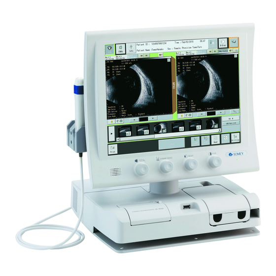
2. NAMES AND FUNCTIONS Front of the main unit (10) 2-01 (11) (1) LCD and touch panel Topographic images, waveforms, and measurements are displayed on the 15” TFT color LCD (1,024 x 768 dots). Operations are performed by touching buttons on the touch panel attached over the LCD. - Page 28 (5) Total gain volume A knob to adjust the gain of an image. (6) Dynamic range volume A knob to adjust the dynamic range of an image. (7) Near gain volume A knob to adjust the near gain of an image. (8) Far gain volume A knob to adjust the far gain of an image.
-
Page 29: Back Of The Main Unit
Back of the main unit 2-02 (11) (10) 2-03 (12) 2-3 ■... - Page 30 (1) Probe holder Houses an axial length probe, corneal thickness probe, and B-probe. (2) Low frequency probe connector Connects a low frequency probe (15MHz B-probe). (3) High frequency probe connector Connects a high frequency probe (60MHz UBM probe). (4) Extension terminal (UH01, UH02) Is a connector for extensions.
-
Page 31: Screen
Screen 2.3.1 Basic structure and common items 2-05 Shown differently in different modes. (8) (9) (10) (11) 2-06 Shown differently in different modes. (12) (13) (14) (1) Eye display field (eye selection button) 2-5 ■... - Page 32 Touching the “R” or “L” button displays the measurement screen for the selected eye. (2) “Probe selection” button Selects a probe to be used for measurement. (3) “Patient information entry” button Opens the patient information entry screen. (4) Patient information field Displays the patient information entered on the patient information entry screen.
- Page 33 Communicating via USB: Disconnect: (12) “Export” button Transmits examination data to TOMEY Link. (13) “Save” button Saves examination data in a USB flash memory. (14) “US <-> OPT” button Switches between the ultrasonic (US) screen and the optical axial length (Opt) screen.
-
Page 34: B-Mode Image Diagnosis
2.3.2 B-mode image diagnosis a) Initial FREEZE screen (10) (11) (12) (13) (14) (15) (1) Movie monitor Displays the real-time image currently being measured and a stored movie. (2) Static-image monitor Displays a static image cut out from a movie and a stored static image. Up to 20 Static images can be called at the same time, which are displayed in the tabular format shown as (8) (3) Thumbnails Display the thumbnails of the images stored in the USB flash memory. - Page 35 (6) “Display” button Displays stored movies, static images, or grouped images on the movie monitor or static-image monitor. (7) Movie tab Displays the attributes of the movie being played. The date is displayed if the saved image is displayed via its thumbnail..
- Page 36 b) FREEZE screen (11) (12) (10) 2-14 (14) (13) (1) Intra-image information Indicates the ID, eye to be examined (R/L), and the examination time and date of the patient. These pieces of information can be shown or hidden in the intra-image information display settings of the utility.
- Page 37 scan mode, and scope of the image. (6) FREEZE menu window Displays the setting menu during the FREEZE state. (7) Play tool Allows you to edit the obtained examination movie data. (Refer to “3.3.6 a) Playing and editing video.”) (8) “Probe set angle selection” button Displays the probe set angle selection window.
- Page 38 c) Real-time screen 2-15 (Fig. 1) (1) Real-time menu window Displays the setting menu during real-time mode. (2) Focal area marker For a 60MHz UBM probe, this marker is displayed in the most focused area. This can be shown or hidden (Refer to “3.12.2 i) intra-image display settings”).
-
Page 39: Axial Length Measurement Auxiliary Function
2.3.3 Axial length measurement auxiliary function a) FREEZE screen 2-17 (1) Data display area Displays the data of the displayed movie or static image. The data include a page number, a scope, a type of gradation characteristics, converted acoustic velocity (mean, lens, anterior chamber / vitreous), an IOL thickness, an implanted lens acoustic velocity. - Page 40 (6) Cursor movement tool Moves a cursor line and the position of each cursor. b) Real-time screen 2-18 (1) Real-time menu window Displays the setting menu during real-time mode. Displays a cursor when an anterior of the cornea, the front of the crystal lens, the back of the crystal lens, or the retina is detected.
-
Page 41: Biometry Function (Available Only While Al-4000 Is Connected)
2.3.4 Biometry function (available only while AL-4000 is connected) a) Measure screen 2-19 (10) (11) (12) (1) Axial length data display Displays the measurement data, mean value, standard deviation, and data range of the axial length. (2) Gain indicator Displays a gain value. (3) Mode display Displays the mode selected in (the axial length setting) on the utility screen. - Page 42 (6) “Retake” button Deletes the measurement data of the displayed eye and returns to the loading screen. (7) Measurement data display Measurement data of the axial length, anterior chamber depth, and crystal lens thickness, and their averages are listed. The following marks are assigned to the measurement data. “*”: Data used for calculating IOL “L”: Longest axial length “S”: Shortest axial length...
- Page 43 b) Edit screen 2-20 (1) Waveforms monitor Displays the measured waveform and memory number. (2) Measurement data display Measurement data of the axial length, anterior chamber depth, and crystal lens thickness, and their averages are listed. The following marks are assigned to the measurement data. “*”: Data used for calculating IOL “L”: Longest axial length “S”: Shortest axial length...
- Page 44 (4) Selection cursor UP/DOWN buttons Moves the selection cursor up and down. (5) “Delete/Restore” button Deletes and recovers the data. (6) “Select” button Selects the data at the selected cursor position to be used for calculating an IOL. The selected data is indicated by an “*.”...
-
Page 45: Light Interference (Opt) Function (Available Only While Oa-1000 Is Connected)
2.3.5 Light interference (Opt) function (available only while OA-1000 is connected) a) Measurement result screen (12) (13) (14) (10) (11) 2-21 (1) Fitting formula display field Displays a fitting formula: Contact -> Immersion -> Optical distance (2) Setting display Displays the settings set at the point of measurement: eye type to be measured , measurement method, Axial Ref., ACD Ref., Pachy Ref. - Page 46 (6) “Measurement mode selection” button Selects measurement data: Axial length, anterior chamber depth, corneal thickness. (7) OPT mode display Indicates the light interference (Opt) mode is selected. (8) Measurement data display Lists axial lengths, measurement data of SNR, and measurement values (∫) calculated by their integral functions, and average values of them.
- Page 47 b) Edit screen 2-22 (1) “Delete/restore” button Deletes and recovers the data. (2) “Select” button The measurement data at the cursor position is selected to be used for calculating IOL power. The selected measurement data is indicated by an “*.” (3) “Apply”...
-
Page 48: Iol Calculation Screen
2.3.6 IOL calculation screen 2-23 a) Post-measurement screen (10) (11) (12) (13) (14) (15) (18) (16) (17) (1) Axial length data display Displays the measurement data, mean value, standard deviation, and data range of the axial length. (2) Gain indicator Displays a gain value. - Page 49 (5) US <-> OPT indication Indicates whether the result has been measured in the ultrasonic wave method or in the light interference method. (6) Parameter field Enter the following parameters used for calculating IOL: Axial length, anterior chamber depth, K1(D), K2(D), desired refractive power. (7) Clinical History Method parameter This is only active when Double k SRK/T is selected in the formula.
- Page 50 (14) Implanted IOL data (IOL power) Enter the IOL model actually implanted in a surgery. (15) Post-operation eye refractive power Enter the eye refractive power after an operation. (16) “Measure”/”Edit Window” button (result by ultrasonic measurement) Displays the Measure Window or Edit Window. For light interference (Opt) mode, the button is labeled as “Measure Window”, displaying a measurement result screen of the light interference (Opt) mode.
-
Page 51: Pachymetry Function (Available Only While Al-4000 Is Connected)
2.3.7 Pachymetry function (available only while AL-4000 is connected) a) Measure/Edit screen 2-24 (10) (11) (12) (13) (14) (15) (16) (17) (1) Real-time data display field Displays the actual measurements of the loaded points. The latest loaded data are displayed during a measurement process. (2) Average and standard deviation of corneal thickness The average and standard deviation of the corneal thickness measurement data is displayed. - Page 52 (5) “Caliper” button Opens the caliper screen. (6) “Meas Point (measurement point)” button Shows and hides measurement points. (7) “Change Meas Point” button Appears when a measurement point is displayed. Pressing this button displays the measurement point change screen. (8) Measurement range selection Allows you to set a measurement range.
-
Page 53: A-Scan Diagnosis (Only When Al-4000 Is Connected)
2.3.8 A-scan diagnosis (only when AL-4000 is connected) a) Freeze screen (10) (14) (11) (12) 2-28 (13) (15) (1) Video display tab Displays an image to be displayed on monitor. (2) Gain indicator Displays the gain value. (3) Analysis tool Displays the tool to be used for the line analysis and the point analysis. - Page 54 (5) “Ref Wave” button Displays the Ref waveform. (6) Displayed information in the image area The patient ID, the tested eye (R/L), and the test date and time are displayed. (7) Image page number Indicates the page number of the image being displayed. (8) Converted acoustic velocity The acoustic velocity for conversion is displayed.
- Page 55 b) Real-time screen 2-30 (1) Real-time menu window Displays the setting menu during real-time mode. 2-29 ■...
- Page 56 (Auto power off function This function automatically turns off the LCD when the instrument is not operated for a specified time (power saving mode). The power lamp (1) flashes. Touch the touch panel (2) to return to normal status. Refer to “3.12.2 a) Common setting” for activation and the time for the auto power off function.
-
Page 57: Operation Procedures
3. OPERATION PROCEDURES Safety precautions ■ Sterilize the B-scan diagnosis probe before use. ■ Do not use a B-scan diagnosis probe with a damaged contact section. Measurement error may occur, as well as the eyelid or cornea may be injured. ■... -
Page 58: Precautions For Installing The Instrument
3.1.1 Precautions for installing the instrument ■ Install the instrument in a location free of water or chemicals. Any water or chemicals entering the instrument may cause an electric shock or failure. ■ Do not install the instrument in a location where chemicals are stored or gases may occur. -
Page 59: Precautions For Connecting The Power Cord
3.1.2 Precautions for connecting the power cord ■ Check the frequency, voltage, and allowable current (or power consumption) of the power source. Otherwise, fire or electric shock may occur. ■ Connect the power plug to a grounded 3-pin outlet. Otherwise, a short circuit due to failure of the instrument may result in electric shock. -
Page 60: Preparation Before Use
Preparation before use 3.2.1 Connections ■ Faulty connection of the instrument and relevant accessories may result in fire, electric shock, or fatal accident. Turn off all devices and disconnect the power plugs from the outlet before connection. ■ The connector needs to be inserted in a specific direction. - Page 61 b) Attaching the arm ■ Screw in the screw and fix it firmly. Otherwise the probe attached to the arm may drop to be damaged or may drop to damage an eye ball or eye lid of the patient. 3-02 (Fig.
- Page 62 c) Attaching probe to arm 3-03 3-04 (Fig. 3) (Fig. 1) Take out the probe holder key (3), which you can find when turning the top cover (2) of the probe holder (1) of the arm away. 3-05 Connected with a probe cable (Fig.
- Page 63 d) Connecting the B-scan diagnosis probe ■ Different connectors are to be connected depending on probe types. Check the type of a probe before connecting it to the right connector. ■ Different connectors are to be used depending on probe types. Check the type of a probe before connecting it to the right connector.
- Page 64 e) Installing the probe cap membrane (60MHz UBM probe) ■ Don’t inject anything other than purified water into the probe when using a probe cap membrane. Otherwise the probe may be damaged. 3-07 (Fig. 1) 3-08 3-09 (Fig. 2) (Fig. 3) Attach the probe cap membrane (1) to the end of the 60MHz UBM probe.
- Page 65 f) Connecting the footswitch 3-10 (Fig. 1) Insert the footswitch connector (1) into the footswitch connector (2) on the back of the instrument, aligning the notches of the connectors. Turn the fixture (3) of the connector clockwise until it stops to secure the connector.
- Page 66 g) Connecting an external digital printer ■ Use only specified video printers and cables. Use a video signal cable or remote cable to connect this instrument to a device conforming to IEC60601-1 or JIS T 0601-1 or conforming to IEC60950-1 and with a power source isolated by an insulated transformer.
- Page 67 h) Connecting an external ID input device 3-13 3-11 [Front] [Back] (Fig. 1) (Fig. 2) Plug the USB cable plug of an external ID input device (e.g. barcode reader) into the USB connector (1) on the front or back of the main unit in the correct orientation.
- Page 68 DATA Transfer. ■ Appropriate connection settings are required for connection with TOMEY Link and DATA Transfer. Refer to “3.10.2 d) Tomey Link connection settings” to make settings. ■ Be sure to make network settings under the consent of your network administrator.
- Page 69 Prepare the following items: - LAN cables (straight type, category 5 or higher): - A network hub (A 100MHz switching hub recommended): - A computer with TOMEY Link or DATA Transfer installed: Hub for LAN [Wiring example] 3-14 To intra-hospital system Bar code reader etc.
- Page 70 [Connection of an USB cable] Prepare the following items. - USB cable: - A computer with TOMEY Link or DATA Transfer installed: To intra-hospital system Bar code reader etc. Computer with TOMEY Link or DATA (Fig.
- Page 71 3-11 (Fig. 2) Plug the USB cable plug B into the USB-D connector (1) on the back of the main unit in the right orientation. Plug the other cable plug A of the USB cable into the USB connector of a personal computer in the correct orientation.
- Page 72 Slowly push and slide the unit to the back. Note that AL-4000 charges itself through the power supply terminal (1) of UD-8000 as long as the instrument is housed in the main body of UD-8000 and UD-8000 is turned ON.
- Page 73 ■ Check that either or both of connected devices is in new patient mode before starting to communicate the patient information and measurement data. Communication cannot be started while both devices contain the information and measurement data of the last patient. Connection methods with AL-4000 include USB connection (wired) and wireless connection.
- Page 74 [USB connection] Plug the USB cable plug A(3) into the USB connector (1) on the back of the main unit in the correct orientation. Insert the USB cable plug B(4) into the USB connector (2) on the top of AL-4000 in the correct orientation. 3-11 3-13 3-12...
- Page 75 l) Connecting OA-1000 Light Interference Method Axial Length Measurement Instrument ■ For the identical-ID mode: Check that either or both of connected devices are in new patient mode when starting to connect the unit with OA-1000. Wired communication cannot be started while both devices contain measurement data.
-
Page 76: Wireless Communication Connection With Al-4000 Measuring Unit
3.2.2 Wireless communication connection with AL-4000 measuring unit ■ This equipment has been tested and found to comply with the limits for a Class B digital device, pursuant to Part 15 of the FCC Rules. These limits are designed to provide reasonable protection against harmful interference in a residential installation. - Page 77 ■ When connecting a device with a USB cable during wireless communicating, wireless connection is changed to wired connection. [Automatic connection upon startup] When the AL-4000 is selected as the “connection place” in this instrument, wireless communication automatically starts when both the AL-4000 and this instrument are turned on.
- Page 78 3-20 (Fig. 2) ■ 3-22...
- Page 79 [Resuming communication from the no communication state] Click the “New” button (1) to clear the existing data. 3-20 (Fig. 1) Select the same measurement mode as that of the AL-4000 in the “mode selection field (2).” Click the “AL-4000 communication check” button (3) to resume communication.
-
Page 80: Turning The Power On And Adjustment After Turning The Power On
3.2.3 Turning the power on and adjustment after turning the power on ■ To restart the system, turn the power off, wait for ten seconds or so, and turn it on again. a) Turning the power on 3-24 (Fig. 1) Turn on the power switch (1) on the side of the instrument. - Page 81 3-26 (Fig. 2) When the B-scan diagnosis probe is correctly calibrated, an eye selection confirmation dialog pops up on the FREEZE initial screen. (Fig. 2) Select the eye to be measured between “R (right eye)” and “L (left eye).” 3-27 (Fig.
- Page 82 b) Adjustment after turning power on ■ Be fully cautious when adjusting the angle of the monitor because you might pinch your finger. ■ Adjust the monitor angle so that you can see the monitor screen right in front of you as much as possible.
-
Page 83: Selecting An Eye
3.2.4 Selecting an eye ■ Select an eye when starting up the instrument, switching an operation mode, and newly measuring an eye. 3-26 (Fig. 1) 3-27 (Fig. 2) On starting up the instrument, changing operation mode, and examining a new patient, the eye selection screen appears. Select the eye to be measured. -
Page 84: Entering/Modifying Patient Information
“DATA Transfer” provided with the Machine is not available for query of the patient data. ■ For details on the TOMEY Link Server settings, refer to the TOMEY Link instruction manual. ■ Appropriate connection settings are required for connection with TOMEY Link. - Page 85 Enter a patient ID (3) using the software keyboard (2) or an external ID input device (e.g. bar code reader). If automatic query to the TOMEY Link is configured, the device will immediately start querying for patient information, etc. For details on...
- Page 86 TOMEY Link, refer to “3.12.2 d) TOMEY Link connection settings.” Refer to “3.2.5 b) Querying patient information (TOMEY Link)” if you want to manually inquire patient information of TOMEY Link. If you select a patient ID from the data stored in the USB memory that is connected to the instrument, press the “USB ID list”...
- Page 87 3-31 (10) (11) (Fig. 4) To register or edit data, touch the box with the physician number you want to register, and enter or modify data using the software keyboard. To delete a physician, touch the box with the physician number you want to delete and make the box blank.
- Page 88 Touch the “Yes” button (12) to retain the measurement data, overwrite the existing patient information with the newly entered data, and return to the previous screen (Fig. 1). Touch the “Cancel” button (13) to return to the previous screen (Fig. 1), retaining the new patient information entered.
- Page 89 3-29 (Fig. 1) Enter a patient ID in the Patient ID field (1) and touch the “TOMEY Link Inquiry” button (2) to start sending a query to the TOMEY Link. When a query of patient information is completed, the patient information is entered in each data field.
-
Page 90: All Clear Of Measurement Data (Preparation For Measuring A New Patient)
3.2.6 All clear of measurement data (preparation for measuring a new patient) ■ The deleted data cannot be restored. Carefully check the data before deleting it. ■ Be sure to touch the “New” button to delete all the measurement data for the previous patient before measuring another patient. -
Page 91: Switching Modes
3.2.7 Switching modes (a) Switching normal modes ■ When the mode is changed, all data captured in the previous measurement mode is deleted. Be very careful when performing initialization. 3-27 (Fig. 1) Touch the “Select mode” button (1) to open the mode selection window (Fig. Select the desired mode and then touch the “OK”... - Page 92 There are following modes: - B-Diag B-mode image diagnosis function - B-Axial Biometry support function - Axial Biometry function (available only when AL-4000 is connected) - Pachy Pachymetry function (available only when AL-4000 is connected) - A-Diag A-mode diagnosis function (available only when AL-4000 is connected) (b) Switching between ultrasound (US) mode and light interference (OPT) mode ■...
- Page 93 3-94 (Fig. 2) Hold the “US <-> OPT switch” button (1) found in a screen for 2 seconds to switch between the ultrasound (US) mode and the light interference mode (Opt). Data obtained in the screen is kept retained after switching between the ultrasound (US) mode and the light interference (Opt) mode.
-
Page 94: B-Mode Image Diagnosis
B-mode image diagnosis 3.3.1 Selecting a probe ■ When the probe is changed, all unsaved data captured by the previous probe is deleted. Be very careful when switching the probe 3-27 (Fig. 1) Switch the probe by touching the “Select Probe” button (1). Only connected probes can be selected by probe switching. -
Page 95: Displaying Probe Angle
3.3.2 Displaying probe angle This function shows the angle in which the B-mode probe is set to diagnose the patient’s eye. ■ Confirm that the displayed probe angle matches the probe angle captured in the picture. Touch the “Select Probe Angle” button (1) to open the probe angle selection window. - Page 96 Select a probe angle button shown in the lower left of the monitor. The selected angle is shown by the probe angle mark (3) in the bottom left of the monitor. “N” means nasal (nose) and “T” means temporal (ear). Touching the arrow button (4) in the center rotates the probe angle mark in the in the clockwise direction as shown below.
- Page 97 15 MHz B probe 60MHz UBM probe The scan mark = the upper side of image The scan mark = the left side of image 3-39 <Understanding the probe angle mark> The scan direction mark (1) on the B-mode probe is indicated by the extending section (2) of the probe angle mark.
-
Page 98: Adjustment By Gain Setting Knobs
3.3.3 Adjustment by gain setting knobs ■ Settings made here are only effective for the eye currently selected. Settings cannot be made for both eyes simultaneously. Complete necessary settings for each eye. Examine the ultrasound image when you make a subtle adjustment using a gain setting knob. - Page 99 c) Near knob (3) Sets the echo reflection sensitivity in the neighborhood of the anterior eye. (Adjustment range: 1 – 60 step) d) Far knob (4) Sets the echo reflection sensitivity in the neighborhood of the retina and the posterior eye. (Adjustment range: 1 –...
-
Page 100: Patient Preparation
3.3.4 Patient preparation ■ Cooperation by the patient is required to perform examination smoothly. Explain the examination method to the patient before starting the examination to help them relax. ■ Make sure that the air is not mixed in when applying the ultrasound diagnosis gel. -
Page 101: Obtaining Ultrasound Image
3.3.5 Obtaining ultrasound image ■ The probe cap membrane is a disposable part. Do not reuse it. Otherwise, you may contract diseases. ■ Do not allow water or chemicals to splash on probes, except for the tip cap. Any water or chemicals entering the instrument may cause an electric shock or failure. - Page 102 (Fig. 1) (Fig. 2) When the instrument is in FREEZE mode, touch the “Scan” button (1) or step on the FREEZE pedal (2) on the footswitch to release the FREEZE mode and make it real time mode. [15 MHz B probe] Apply an appropriate amount of the ultrasound diagnosis gel to the contact section of the B-mode probe.
- Page 103 [Probe with a membrane cap attached] <When an eye cup is not used> Apply an appropriate amount of the cornea protective agent to the contact section of the membrane cap or the examined eye. Apply the tip of the membrane cap directly to the lid of the examined eye. <When an eye cup is used>...
-
Page 104: Various Functions In Freeze Mode
3.3.6 Various functions in FREEZE mode Functions that are enabled in the freeze menu vary depending on the selected probe. See to the following table. Table 1 Freeze menu functions for individual probes 15MHz 60MHz Vector-A ○ × Smoothing ○ ×... - Page 105 a) Playing and editing video This instrument stores maximum of 400 images of the 15 MHz B probe or maximum of 100 images of the 60 MHz UBM probe. This function provides a playback tool for video operations of playback, frame advance and reverse, extraction, export, and saving.
- Page 106 [Playing Movie] 3-33 (Fig. 1) 3-47 (Fig. 2) Touching the “Play” button (1) plays the stored images in series as a video. The “Stop” button (Fig. 2) is shown while a video is played. While a video is run, the play position cursor (2) is displayed on the play bar (3) indicating the position of the image being played.
- Page 107 [Extract Movie] This function allows you to specify the range of the video to be played, sent, or saved. 3-48 (Fig. 1) A range of the video is specified by moving the extraction cursors (1), so that the video range between the cursors can be played, sent, or saved. [Exporting Movie] This function sends a range of the video displayed on the monitor, the range having been specified by the video extraction function.
- Page 108 b) Commenting This function adds comments to videos and images. 3-33 (Fig. 1) Touching the “Comment” button (1) displays the input comment window (Fig. 2) and the software keyboard on the monitor. 3-49 (Fig. 2) (2) (3) ■ 3-52...
- Page 109 Enter a comment using the software keyboard. Touching the “Add” button (2) saves the entered comment and closes the comment input window. If the utility is so set that the comment is displayed in the image, the entered comment is displayed in the image (See “3.12.2 i) Image display settings.”) The comment is saved when the image is saved, and is discarded when the image is discarded.
- Page 110 Select a vector-A button (1) in the FREEZE menu window to switch on or off the mode-A waveform display. Selecting “ON” displays the vector-A tool (2), the cursor line (3), and the mode-A waveform for the line position. The mode-A waveform of the cursor line position is shown on a real-time basis as you move the cursor line by touching the “Move Cursor Line up (or down)”...
- Page 111 e) Zoom This function magnifies the displayed image. The vector mode-A cannot be used when the zoom is used. 3-51 (Fig. 1) Open the zoom navigation window (2) by touching the “Nav.” button in “Zoom” in the FREEZE menu window. 3-52 (Fig.
- Page 112 3-53 (Fig. 3) The current magnification is displayed in the magnification display frame (4). Touching the image by the magnification tool (5) magnifies the image around the touched point. Five magnification rates are provided: 100%, 125%, 150%, 200%, and 300%. Touching the image by the reduce tool (6) reduces the image around the touched point.
- Page 113 f) Measurement This function measures lengths, angles, and areas of the image displayed on the monitor. ■ When you use the result of this function for operations and medical treatments, make a comprehensive decision considering the results of other measurement devices and differences between the left and right eyes.
- Page 114 (Fig. 2) Select a tab (3) to display an analysis tool (length, angle, or area). ■ The measurement points and results are all deleted when the measurement tool is closed, and they cannot be recovered. ■ The sound speed that has been modified returns to the default value when the measurement tool is closed.
- Page 115 [Length measurement] This function measures and displays the distance between two arbitrary points in an image. The “x”, +”, or “*” caliper mark is placed at two points in the image and their distance is displayed. One of the caliper mark is shown in red (active caliper), and the other is shown in the same color as the measurement result name displayed on the “Measurement Target Selection”...
- Page 116 The measurement result name (8) in the image is displayed and hidden every time the “Line Name” button (5) is touched. Touching the “Perpendicular Line” button (6) displays two lines (9), each of which passes through one of the caliper marks and is perpendicular to the line that passes through the two caliper marks.
- Page 117 10) Touching the “Clear Length(s)” button (12) clears the all measurement results being displayed. 11) Touching the “Change Setting” button (13) displays the setting change window (Fig. 3). 3-57 (16) (15) (14) (Fig. 4) 12) Enter an acoustic velocity and a measurement result name. Touch the “Apply”...
- Page 118 [Angle measurement] This function measures and displays the angle determined by three arbitrary points in an image. The “x” or “+” caliper mark is placed at three points in the image and the angle determined by them is measured. One of the caliper marks is shown in red (active caliper), and the others are shown in the same color as the measurement result.
- Page 119 The line between caliper marks in the image is displayed and hidden every time the “Line” button (4) is touched. The measurement result name in the image is displayed and hidden every time the “Line Name” button (5) is touched. [Area measurement] This function measures a target area and displays the result.
- Page 120 g) Anterior Analysis ■ When you use the result of this function for operations and medical treatments, make a comprehensive decision considering the results of other measurement devices and differences between left and right. ■ The FREEZE menu window is enabled when the 60 MHz UBM probe is selected.
- Page 121 3-60 (Fig. 2) Open the “Anterior Analysis” tool (Fig. 2) by touching the “Anterior Analysis” button (1) in the FREEZE menu window. ■ The zoom function is unavailable while the anterior analysis tool is open. Apply the zoom function and then open the anterior analysis tool to analyze the enlarged image..
- Page 122 [Angle analysis] 3-361 (Fig. 1) The message display area (1) displays the explanation and alert messages for the analysis. Touching the “SS” button (2) and then the SS (Sclera) point in the image displays an SS point at that point and circles with diameters of 500-um and 750-um regarding the displayed SS point as the center (Fig.
- Page 123 3-362 (11) (10) (Fig.2) The angle is automatically analyzed immediately after the SS point and TMPLANE are specified on the image. Automatic analysis automatically detects analysis points to calculate AOD250, AOD500, AOD750, ARA500, ARA750, TISA500, TISA750, and TIA500 (Fig. 2). However, analysis points sometimes cannot be detected automatically depending on the image status.
- Page 124 ■ Refer to “Angle analysis parameter list” for details of parameters. When moving the SS point and/or TMPLANE point for adjustment, other angle analysis points disappear from the image. Touch the "Analyze" button (6) to display the result after re-analysis. When adjusting SS-IF, AOD250-IF, AOD500-IF or ARA-IF point, each point moves to be vertical to the SS-TMPLANE line.
- Page 125 < List of angle analysis points > Sclera: The angle corner side of the line segment that constitutes the trabeculum plain TMPLANE The cornea side of the line segment that constitutes the trabeculum plain SS-IF The intersection of the iris anterior surface and the line that crosses SS and is vertical to the line that crosses SS and TMPLANE AOD250-T...
- Page 126 3-62 (Fig.3) ■ 3-70...
- Page 127 [Iris analysis thickness] (1) (2) 3-363 (Fig. 1) The message display area (1) displays prompt messages for entering and adjusting each point. Touching the “SS” button (2) and then the SS (Sclera) point in the image displays an SS point at that point and circles with diameters of 500-um, 750-um, and 2-mm regarding the displayed SS point as the center (Fig.
- Page 128 3-364 (Fig.2) The iris is automatically analyzed immediately after the SS point and TMPLANE are specified on the image. Analysis points are detected automatically to calculate ID1, ID2, ID3, TCPD, and ICPD (Fig. 2). However, analysis points sometimes cannot be detected automatically depending on the image status.
- Page 129 When moving the SS point and/or TMPLANE point for adjustment, other iris thickness points disappear from the image. Touch the “Analyze” button (6) to display the results after re-analysis. 3-365 (Fig.3) When the T3 line is not paralell to the iris, specify T3-I1 and T3-I2 so that the T3 line becomes parallel to the iris.
- Page 130 (10) (11) 3-366 (13) (Fig. 4) (12) 10) When measuring ID3, touch the “ID3-IF” button (10), “ID3-IB” button (11), and then the image. The ID3 line appears. Touch the image or the cursor button (3) to move the point as needed. Touch the “Analyze” button (6) to display the results after re-analysis (Fig.
- Page 131 < List of iris thickness parameters > Distance between ID1-IF and ID1-IB Distance between ID2-IF and ID2-IB Distance between ID3-IF and ID3-IB TCPD Distance between AOD500-T and TCPD-CB ICPD Distance between ID1-IB and TCPD-CB < List of iris thickness points > T3-I1 Terminal point 1 of line T3 T3-I2...
- Page 132 3-63 (Fig. 5) ■ 3-76...
- Page 133 h) Image print This function prints the image of the page displayed on the monitor. 3-33 Touching the “Image Print” button (1) prints the image of the page (2) displayed in the monitor to the printer specified by the utility (refer to “3.12.2 e) Print settings”).
- Page 134 In addition, when the data is sent to TOMEY Link, TOMEY Link recognizes that all the received data without the ID number belongs to the same patient. Pay extreme attention not to mishandle the data.
- Page 135 3-33 (Fig. 1) Select a still image or a video to send over TOMEY Link, and touch the “EXPORT” button (1) to send the still image or the “Export Movie” button (2) to send the video. For a still image transfer, the frame currently displayed is transferred;...
- Page 136 j) Saving image This function saves the displayed image to an external storage medium in the Echo data format or JPEG data format. Echo data format: Data saved to an external storage medium in this format can be read and displayed by this instrument again.
- Page 137 [Saving still image in Echo] 3-33 (Fig. 1) Display the video to be saved in the FREEZE screen, and specify the range of the video to be saved using the video extraction function. Save the video in an external storage medium by the “Save Echo” button (1) or “SAVE/PRINT”...
- Page 138 [Saving video in Echo] 3-33 (Fig. 1) Specify the range of the video to be saved using the video extraction function. (Refer to “3.3.6 a) Playing and editing video.”) Touch the “Save Movie” button (1) to save the video in an external storage medium.
- Page 139 [Saving in JPEG] 3-33 (Fig. 1) Display, on the FREEZE screen, the still image to be saved in JPEG. Touching the “Save JPEG” button (1) displays the filename input window and the software keyboard. 3-67 (Fig. 2) Enter the name for the filename. The length of the filename must be 32 characters or less.
- Page 140 k) Extracting still images This function extracts a frame of the video and displays it on the still image monitor. An image that has been extracted by this function can be saved in Echo, saved in JPEG, group-saved, printed, transmitted, and analyzed. Maximum of 20 frames can be extracted for each eye.
- Page 141 In addition, when the data is sent to TOMEY Link, TOMEY Link recognizes that all the received data without the ID number belongs to the same patient. Pay extreme attention not to mishandle the data.
- Page 142 Use the still image extraction function to extract images to be group-exported to the still image monitor. (Refer to “3.3.6 (k) Extracting still images.”) Touching the “Group EXPORT” button (1) shows a confirmation window. Check the content of the confirmation window, and touch the [OK] button to group-export the images.
- Page 143 m) Group saving This function saves unsaved images displayed on the still image monitor as a group. Images measured with the same mode and the same probe are bundled as a group, and are saved in the Echo data format. ■...
- Page 144 Check the content of the confirmation window, and touch the [OK] button to group-save the images. The group-saved images are grouped and added to the thumbnail image list. ■ 3-88...
- Page 145 n) Displaying, editing, deleting stored images This function displays and edits videos and still images saved in an external storage medium in the Echo data format. ■ Do not remove the external storage medium during data saving. This may destroy not only the data being saved, but also other data in the external storage medium.
- Page 146 <Thumbnail icons> The [Display] button on a thumbnail indicates the type of the image: video, still image, or group images. 3-70 Video icon 3-71 Still image icon 3-72 Group image icon: You can also select an image to be displayed from the data list. Touch the “Meas.
- Page 147 [Deleting data in an external storage medium] ■ This function is used exclusively when viewing videos and still images saved in an external storage medium. ■ The deleted data cannot be restored. Be very careful when performing initialization. This function deletes videos and still images saved in an external storage medium (USB memory).
- Page 148 o) Displaying, editing, deleting group images ■ Check that the instrument is correctly grounded. ■ Do not remove the external storage medium while viewing, editing or saving data. This may destroy not only the data being saved, but also other data in the external storage medium.
- Page 149 [Functions available on the group menu] 3-75 (Fig. 1) (1) Group menu display buttons: Displays the group menu (2). (2) Group menu: Displays the functions for group images. (3) Page field: Indicates the currently displayed page number within the group in the format of “page number/total pages.”...
- Page 150 [Deleting group data from USB memory] ■ The deleted data cannot be restored. Be very careful when deleting data. This function displays images to be deleted on the FREEZE screen. 3-75 (Fig. 1) Touching “Delete this Page” button (1) deletes the image currently displayed from the group.
- Page 151 p) Dual display This function divides the still image monitor into two screens. 3-76 (Fig. 1) The dual display and the standard display switch each other every time the “DUAL Display” button (1) is touched. 3-95 ■...
- Page 152 q) Quad display This function displays up to four images simultaneously out of the images displayed in the video monitor or the still image monitor. The operations on this display mode are limited to playing videos and frame-by-frame viewing of group-saved images.
- Page 153 3-78 (Fig. 2) ■ Videos can only be displayed on the upper left screen. Touch the “Image Switch” buttons (2) to select an image to be displayed. Touch the “Play” button (3) to play the video. Touch the “Previous/Next” buttons (4) to switch images in the group. Touch the “Back”...
- Page 154 r) R/L alignment display This function aligns the tabs of the patient's left and right eyes simultaneously on the screen. 3-77 (Fig. 1) Touch the “R/L” button (1) to display the R/L-aligned display screen. 3-79 (Fig. 2) ■ 3-98...
- Page 155 Touch the screen switch button “Movie” or “Still” (2) to switch the content displayed on the monitor. Touching the “Go to Freeze Screen” button (3) or a “select patient’s eye” button returns you to the single eye screen. 3-99 ■...
- Page 156 s) Changing total gain and dynamic range after freezing 3-43 (Fig. 1) This function changes the total gain and the dynamic range after freezing. Adjust the values by the TOTAL (1) and DYNAMIC RANGE (2) gain setting knobs. The adjustable ranges are plus and minus 10 dB for the total gain, and plus and minus 10 dB for the dynamic range.
-
Page 157: Various Functions In Real Time Mode
3.3.7 Various functions in real time mode Functions that are enabled in the real-time menu vary depending on the selected probe. See the following table: Table 1: Real-time menu functions for individual probes 15MHz 60MHz Vector-A ○ × Smoothing ○ ×... - Page 158 c) Switching frequency ■ Switching by this function can be made only when the 15 MHz B probe is used. Select a frequency setting (1) from 15 MHz, 20 MHz, and Harmonic. 3-80 [Characteristics of individual settings] Mode Characteristics 15MHz Performs the standard observation of the retina, vitreous, and eye posterior area.
- Page 159 d) Switching the scan mode Select a scan mode setting (1) from “Basic” and “High Sensitive.” The high sensitive mode reduces the noise and increases the SN ratio by summing multiple received ultrasound signals. The frame rate, however, is a litter lower.
- Page 160 f) Target setting Make a selection from the four types: “Micro”(child), “Normal”, “Long”, and “Retro” (1). 3-80 (Fig. 1) ■ 3-104...
- Page 161 g) Preset values of gains and dynamic ranges This instrument has three preset value sets of the total gain, dynamic range, near gain, and far gain. This instrument also allows three different user settings to be made. 3-80 (Fig. 1) Select a preset setting from Image Quality (1).
- Page 162 [Wide Dynamic Range] Its gradation granularity is high, so that it suits observation of subtle differences of tissues. This mode, however, tends to capture unnecessary echoes and artifacts (virtual images created by inflections and reflections of ultrasound beams). This mode mainly suits the observation of opacity and bleed in a corpus vitreum.
-
Page 163: Biometry Support Function
Biometry support function ■ This function only supports biometry measurement and is not the function for biometry measurement itself. ■ This function can be used only when the 15 MHz B probe is used This function provides, using B-mode images, information for helping the selection of valid measurements when there is a difficulty in selecting them because of the unstableness of the measurements obtained by the standard biometry function due to the illness of the patient’s eye. -
Page 164: Obtaining Ultrasound Image
3.4.1 Obtaining ultrasound image ■ Be sure that the screw is not loose when you use the arm. A loose screw may cause the probe attached to the arm to drop, which may damage the probe or injure the patient's eye or eye lid. Operating the arm directly with your hand may injure your finger pinched by the arm. - Page 165 3-45 (Fig. 2) [When an eye cup is used] Make preparation for the patient according to the description in “3.3.4 Patient preparation.” When the instrument is in the FREEZE mode, touch the “Scan” button (1) or step on the FREEZE pedal (2) on the footswitch to release the FREEZE mode.
- Page 166 To obtain another ultrasound image of the same patient, touch the “Scan” button (1) or step on the FREEZE pedal (2) of the footswitch to release the FREEZE mode. ■ 3-110...
-
Page 167: Various Functions In Freeze Mode
3.4.2 Various functions in FREEZE mode a) Playing and editing video Refer to “3.3.6 (a) Playing and editing video” for details. b) Commenting Refer to “3.3.6 (b) Commenting” for details. c) Image print Refer to “3.3.6 (h) Image print” for details. d) Sending patient’s data (Export) Refer to “3.3.6 (i) Sending patient’s data (Export)”... - Page 168 f) Moving cursors and cursor line (5) (6) (7) 3-82 (Fig. 1) Touching a “Move Cursor Line” button (1) moves the cursor line up and down. The cursors of cornea anterior , crystal lens anterior, crystal lens posterior, and retina move to their detection positions when the cursor line is moved.
- Page 169 g) Displaying, editing, deleting stored images Refer to “3.3.6 (n) Displaying, editing, deleting stored images” for details. h) Dual display Refer to “3.3.6 (p) Dual display” for details. i) R/L alignment display Refer to “3.3.6 (r) R/L alignment display” for details. j) Changing total gain and dynamic range after freezing Refer to “3.3.6 (s) Changing total gain and dynamic range after freezing”...
-
Page 170: Various Functions In Real Time Mode
3.4.3 Various functions in real time mode a) Eye type setting 3-83 (Fig. 1) Touch any of the “Eye Type” buttons to set the eye to be measured. Select the material in the case of an eye with IOL. Touch the “Change Setting” button (2) to open the setting change screen (Fig. - Page 171 Entry boxes for the acoustic velocities required for the measurement conditions currently set appear. Enter the converted acoustic velocity for the examined eye using the software keyboard being displayed at the same time. Touch the “Ent (enter)” key to apply the setting and proceed to the next entry box.
- Page 172 Touch the “Cancel” button (7) to ignore the entered settings and close the setting change screen. Touch the “Apply” button (8) to apply the entered settings and close the setting change screen. b) Scoping Refer to “3.3.7 (e) Scoping” for details. c) Gradation characteristics Chose an amplifier characteristic from “Log”...
-
Page 173: Axial Length Measurement Display Function (Available Only When Al-4000 Is Connected)
Axial length measurement display function (available only when AL-4000 is connected) 3.5.1 Setting measurement conditions a) Setting the eye to be measured, the axial length calculation method, and the converted sonic velocity ■ Settings made here are only effective for the eye currently selected. - Page 174 Dense cataract eye 〇 〇 △ Aphakic eye 〇 IOL eye (All materials) 〇 〇 〇: Measurements are displayed. △: Measurements may not be displayed. *: Measurements are not displayed. 3-85 3-86 (Fig. 2) Click the “Change Setting” button (1) to open the measurement condition setting menu (Fig.
- Page 175 3-87 – – (10) (11) (12) (Fig. 3) Entry boxes for the sonic velocities required for the measurement conditions currently set appear. Enter the converted sonic velocity using the software keyboard (6). After the entry, touch the “Enter” key (7) to move to the next entry box. Also, by touching the “Incorporate in L”...
- Page 176 (Initial setting and setting range of converted acoustic velocity) ■ Phakic eye Average acoustic velocity for axial : 1,550 m/s, 1,500 - 1,600 m/s length Crystal lens acoustic velocity : 1,641 m/s, 1,540 - 1,740 m/s Anterior chamber depth acoustic : 1,532 m/s, 1,430 - 1,630 m/s velocity Vitreous acoustic velocity (divisional...
-
Page 177: Measurement
3.5.2 Measurement See the user’s manual of AL-4000 measuring unit for the actual procedure of measurement. This section describes the operations that can be performed with this instrument during measurement. ■ The converted acoustic velocity directly affects the measurement data. Check that the desired value is set before starting measurement. - Page 178 a) Setting gain ■ Settings made here are only effective for the eye currently selected. Settings cannot be made for both eyes simultaneously. Complete necessary settings for each eye. 3-43 (Fig. 1) Gain can be changed by turning the total gain volume (1). The set value is displayed in the gain display (2).
- Page 179 b) Setting gate cursor ■ Settings made here are only effective for the eye currently selected. Settings cannot be made for both eyes simultaneously. Complete necessary settings for each eye. 3-88 Gate cursor for cornea Gate cursor for the front of lens Gate cursor for the back of lens Gate cursor for retina (Fig.
- Page 180 c) Re-measurement of the same patient ■ The deleted data cannot be restored. Carefully check the data before deleting it. ■ Be sure to touch the “New” button to delete all the measurement data for the previous patient before measuring another patient. If the data of the next patient is captured without touching the “New”...
-
Page 181: Checking Waveforms After Measurement
3.5.3 Checking waveforms after measurement a) Displaying the optional waveform data 3-35 (Fig. 1) When all necessary measurement data is captured or when the “Edit Window” button (1) is touched, the edit screen (Fig. 2) opens. 3-89 (Fig. 2) The waveform measured at the selected cursor (2) is displayed in the waveform display field (3). - Page 182 b) Selecting specific axial length data to be used for calculating IOL power The average value is normally adopted for the measurement data to be used in calculating the IOL power, but specific data can also be selected. 3-90 (Fig. 1) Use the “selection cursor movement”...
- Page 183 c) Deleting and recovering specified measurement data 3-90 (Fig. 1) Use the selection cursor movement buttons (1) to move the selection cursor (2) to the data which is to be deleted. When the “Delete” button (3) is touched, only the selected data is deleted and the average value is recalculated.
- Page 184 d) Gate change function 3-90 (Fig. 1) Use the “selection cursor movement” buttons (1) to move the selection cursor (2) to the data which is to be changed. Touch the “Gate” button (3) to open the gate change screen (Fig. 2). (10) 3-92 (8) (9)
- Page 185 If you have edited it mistakenly, touch the “Initial Position” button (7) to cancel the changes made, and the gate cursor will return to the position before the editing. When you touch the “Apply” button (8), the changes made are applied, and the measurement data displayed in the measurement data display field (10) is overwritten with the edited measurement data, and the gate change screen is closed.
- Page 186 e) Caliper function ■ Values measured and displayed using the caliper function are rough estimates and may differ from the actual measurement result. This function is used to measure the distance at an arbitrary section of the measurement waveform. 4 dotted caliper lines appear, and the distance between these 2 points is displayed.
- Page 187 Touch the active caliper line switching button (4) to select the caliper line to be changed. The selected caliper line is displayed in red but the other lines are displayed in yellow. Touch the caliper line movement buttons (5) to change the caliper line position.
-
Page 188: Calculation Functions In Light Interference (Opt) Mode
Calculation functions in light interference (Opt) mode Switch to the light interference (Opt) mode by referring to “3.2.8 Switching modes.” 3.6.1 Selection of patient ID handling method ■ In the same ID use mode, the same ID is used among all the instruments being connected. -
Page 189: Displaying Waveform Of Arbitrary Measurement Data
3.6.3 Displaying waveform of arbitrary measurement data It is possible to call up and check the measurement waveform of any measurement data. 3-95 (Fig. 1 Axial length mode) 3-270 (Fig. 2 Corneal thickness mode) After capturing all the needed measurement data, the measurement data and its waveform are displayed. - Page 190 Touch the “measurement mode selection” button (1) to display the measurement data in the order of Axial -> ACD -> Corneal thickness. In the corneal thickness mode, when the measurement data received from OA-1000 contains CCT (ultrasonic correction value for corneal thickness) (2), it is displayed in the measurement data display field.
-
Page 191: Selecting Specific Axial Length Data To Be Used In Calculating Iol Power
3.6.4 Selecting specific axial length data to be used in calculating IOL power The average value is normally adopted for the measurement data to be saved or used for calculating the IOL power, but specific data can also be selected. 3-95 (Fig. -
Page 192: Deleting And Recovering Specified Measurement Data
3.6.5 Deleting and recovering specified measurement data 3-96 (Fig. 1) Use the “selection cursor movement” buttons (1) to move the selection cursor (2) to the data which is to be deleted. Use the scroll bar (3) to move the waveform being displayed to the left or right. - Page 193 If you have deleted data mistakenly or want to cancel the deletion, move the selection cursor (2) to that data number and touch the “Return” button (6) to cancel the deletion. However, once the screen returns to the measurement result screen, the deleted data cannot be restored by the “Return”...
-
Page 194: Caliper Function
3.6.6 Caliper function ■ Values measured and displayed using the caliper function are rough estimates and may differ from the actual measurement result. This function is used to measure the distance at an arbitrary section of the measurement waveform. The distance from the corneal measurement line (Fixed) that displays the position of the corneal waveform to the caliper line is measured. - Page 195 The measurement value is displayed in the measurement data display field (4) in real time. Use the scroll bar (5) to move the waveform being displayed to the left or right. In addition, by touching the “Zoom” button (6), the displayed waveform is enlarged or reduced according to the 4 preset levels.
-
Page 196: Iol Power Calculation
IOL power calculation ■ When using the result of biometry for calculation of the IOL power, the physician must examine the measurement result beforehand. 3-20 (Fig. 1) Touch the “IOL Calculation Window” button (1) on each screen to open the IOL calculation screen (Fig. -
Page 197: Calculation
When using the result of biometry for calculation of the IOL power, the physician must examine the measurement result. ■ Calculation by UD-8000 may produce some errors due to the number of significant digits in internal calculations. ■ Complex numbers may be generated for the SRK/T formula. -
Page 198: Entering Calculation Parameters
3.7.2 Entering calculation parameters a) Axial length and ACD When a measurement is completed, the axial length and the ACD are already entered automatically and cannot be entered manually. (Refer to “3.5.3 b) Selecting specific axial length data to be used in calculating IOL power.”) When measurement has not yet been performed, enter the data as follows. - Page 199 b) Corneal refractive power and radius of corneal curvature (K1/K2) (1) (2) 3-101 (Fig. 1) Touch the K1 input field (1) or the K2 input field (2) to activate it. The keypad (3) appears. Enter the data using the keypad (3), and touch the “Enter” key (4) to reflect [Acceptable range] Corneal refractive power: 30.00 D - 60.00 D...
- Page 200 c) Desired refractive power 3-102 (Fig. 1) Touch the Desired Ref. input field (1) to activate it. The keypad (2) appears. Enter the data using the keypad (2), and touch the “Enter” key (3) to reflect [Acceptable range] -30.00 D – +10.00 D The entered value is stored in the main unit, and does not disappear even when the power is turned off.
- Page 201 d) Lends constants (A-constant/SF/ACD-constant/a0・a1・a2) Enter various lends constants for IOL according to the formula. This instrument is able to calculate up to 4 constants for 1 formula simultaneously. The formula (1) corresponds to the lends (2) and (3), and the formula (4) corresponds to the lends (5) and (6). There are 2 ways to enter the values.
- Page 202 Touch an input field (1) to activate it. The keypad (2) appears. Enter the data using the keypad (2), and touch the “Enter” key (3) to reflect [Acceptable range] A-constant: 100.00 – 130.00 ACD-constant: 0.00 – +10.00 -5.00 – +10.00 ●...
- Page 203 e) Entering parameters for Clinical History Method It is activated only when Double K SRK/T is selected as the formula. 3-105 (Fig. 1) Manually enter the corneal refractive power or radius of corneal curvature before the surgery for correcting the refractive power in PreK1 and PreK2 (1).
-
Page 204: Setting Iol Power Formula
3.7.3 Setting IOL power formula Select an IOL power formula from the following 8 formulas: - SRK-II formula - SRK/T formula - HOLLADAY formula - Hoffer Q formula - HAIGIS optimized formula - HAIGIS standard formula - SRK SHOWA formula - Double K SRK/T e formula 3-99 (Fig. -
Page 205: Entering Data After Surgery
3.7.4 Entering data after surgery Select the IOL type name which was actually implanted in the surgery. 3-106 (Fig. 1) Enter the implanted IOL model. When the entry field (1) is touched, it is activated. Select the IOL model which was actually implanted in the surgery from the list (2). -
Page 206: R/L Alignment Display Function
3.7.5 R/L alignment display function This function simultaneously displays data of left and right eye by displaying two aligned tabs which contain data of the patient’s left and right eye respectively. However, this screen can only be used for viewing, and it is not possible to perform setting or editing on it. -
Page 207: Corneal Thickness Measurement Display Function (Available Only When Al-4000 Is Connected)
Corneal thickness measurement display function (available only when AL-4000 is connected) 3.8.1 Setting the data type to be displayed Select the measurement data type to be displayed from the following three options. Latest: Displays the last measurement data taken. Minimum: Displays the minimum value of measurement data. - Page 208 3-111 (Fig. 2) Use the various setting buttons (2) and the “measurement range setting” button (3) to perform settings for the following items: ■ Measurement mode ■ Method for displaying converted sonic velocity and bias value ■ Selection of measurement data display ■...
- Page 209 a) Measurement mode Select the measurement mode from the following two options. ■ Auto mode Select this for measurement in Auto mode. ■ Manual mode Select this when it is difficult to measure in Auto mode or when measurement values are captured while not performing a measurement.
- Page 210 b) Method for setting converted sonic velocity and bias value Select how to display the bias value from the following two options. ■ Percentage bias Converts the actual measurement using the preset bias rate (percentage) and displays the result. ■ Plus/minus bias Adds/subtracts the preset correction value to/from the actual measurement, and displays the result.
- Page 211 When the converted sonic velocity entry field (2) is touched, it is activated. Enter converted sonic velocity using the keypad. Initially, it is set to 1640 m/s. [Acceptable range] Converted acoustic velocity: 1400 - 2000 m/s Touch the “Display of Bias” button (3) to select the percentage bias (%) or plus/minus bias (μm).
- Page 212 d) Measurement range Set the measurement range according to the object to be measured. 3-113 (Fig. 1) Touch the measurement range selection (1) to display the pull-down menu. Select the desired measurement range. ■ 150 – 350 μm ■ 300 – 1000 μm ■...
- Page 213 e) Displaying and setting measurement points This function displays and sets the location of measurement points. Section above the horizontal axis Section below the horizontal axis 3-114 The measurement point indicates “diameter – angle – S/I.” ■ Diameter: Radius from the center (mm) ■...
- Page 214 3-116 (Fig. 2) When a desired box on the measurement point change screen (Fig. 2) is touched, the box is activated. Set values using the keypad and the like. As for the setting of “S/I,” the indication switches between “S” and “I” each time the display button (4) is touched.
- Page 215 f) Intraocular pressure correction function This instrument automatically starts calculation and displays the result when all items required for calculating the intraocular pressure correction are set. 3-115 (Fig. 1) Touch the “IOP” button (1) to open the intraocular pressure correction screen (Fig.
- Page 216 The input fields of the parameter 1 (3) and parameter 2 (4) for the intraocular pressure correction formula become active when touched, and the keypad appears. Also, when a formula selection button is touched, the already set parameters are displayed in the intraocular pressure correction formula.
- Page 217 g) Subtraction display function This function displays the difference value between the 2 selected measurement data. 3-115 (Fig. 1) Touch the “Subtraction display” button (1) to open the subtraction display screen (Fig. 2). When a measurement has already been completed at this point, the measured values are displayed in the data 1 display field (2).
- Page 218 3-119 (Fig. 3) Touch the “Data Display” button (4) to display the selected measurement data in the subtraction display screen. When measurement data are selected in Data 1 and Data 2, the difference value between Data 1 and Data 2 is displayed in the subtraction display field (5).
- Page 219 g) R/L alignment display function This function simultaneously displays data of left and right eye by displaying two aligned tabs which contain data of the patient’s left and right eye respectively. However, this screen can only be used for viewing, and it is not possible to perform setting or editing on it.
-
Page 220: Measurement
3.8.3 Measurement See the user’s manual of AL-4000 measuring unit for the actual procedure of measurement. This section describes the operations that can be performed with this instrument during measurement. ■ The converted acoustic velocity directly affects the measurement data. Check that the desired value is set before starting measurement. - Page 221 a) Re-measurement of the same patient ■ The deleted data cannot be restored. Carefully check the data before deleting it. ■ Be sure to touch the “New” button to delete all the measurement data for the previous patient before measuring another patient. If the data of the next patient is captured without touching the “New”...
-
Page 222: Checking The Measurement Data
3.8.4 Checking the measurement data a) Intraocular pressure correction It is possible to perform intraocular pressure correction after measurement. (Refer to “3.8.2 f) Intraocular pressure correction function”) b) Deleting part of measurement data 3-115 (Fig. 1) Touch a memory number (1) to select the data to be deleted. Touch the “Delete”... - Page 223 c) Caliper function The caliper function is for temporary reference and cannot store the calipered data. 3-115 (Fig. 1) Touch the “Caliper” button (1) to display the caliper screen (Fig. 2). 3-124 (Fig. 2) Touch the “Switch” button (2) to select a caliper line to be adjusted. The active caliper line is displayed in red and the other caliper line in yellow.
- Page 224 Touch the “Close” button (4) to close the caliper screen (Fig. 2) and return to the previous screen (Fig. 1). ■ 3-168...
-
Page 225: A-Scan Image Diagnosis Display (Only When Al-4000 Is Connected)
A-scan image diagnosis display (only when AL-4000 is connected) 3.9.1 Switching to the A-scan diagnosis display Switch to the A-scan diagnosis referring to “3.2.8 Switching modes.” The initial screen to allow you to check the Ref. data when switching modes is displayed. -
Page 226: Setting Analysis Method
3.9.2 Setting analysis method 3-592 (Fig. 1) Touch the menu tab to open the real time menu window. Select either analysis method (1). When the analysis method is selected, the analysis tool (2) changes according to the selection. ■ 3-170... -
Page 227: Measurement
3.9.3 Measurement Refer to the operation manual of the AL-4000 measurement unit for the actual measurement procedure. Explained in this section is the operation of this instrument relevant to the measurement. ■ The converted acoustic velocity directly affects the measurement data. Check that the desired value is set before starting measurement. - Page 228 a) Gain setting ■ Settings made here are only effective for the eye currently selected. Settings cannot be made for both eyes simultaneously. Complete necessary settings for each eye. Adjust the waveform height according to the gain settings. The gain and the waveform height increases as the gain value increases.
-
Page 229: Various Functions In Freeze Mode
3.9.4 Various functions in FREEZE mode a) Switching data display 3-594 (Fig. 1) This instrument stores up to 100 waveform data sets. Captured waveform data is displayed in order every time the “Frame forward/back” button (1) is touched. 3-173 ■... - Page 230 b) Setting the beam direction Use this function to change the position to apply the probe or the direction of the ultrasound beam, or to display the position of a point of note (with pathocological changes, etc.). (3) (4) 3-655 (Fig.
- Page 231 c) Printing image Refer to “3.3.6 h) Image print” for details. d) Sending patient’s data (Export) Refer to “3.3.6 i) Sending patient’s data (Export)” for details. e) Saving image Refer to “3.3.6 j) Saving image” for details. Movie cannot be saved. The following content in the Echo data is to be saved when saving the still image.
-
Page 232: Various Functions In Real Time Mode
3.9.5 Various functions in real time mode a) Gradation characteristics Select a gain curve from Log, Linear, and S (1) for converting the ultrasound obtained from the echo of the ultrasound transmitted from the ultrasound transducer. 3-598 (Fig. 1) b) Setting the beam direction Refer to “3.9.4 b) Setting the beam direction.”... -
Page 233: Analysis Function
3.9.6 Analysis function a) Line analysis 3-599 (Fig. 1) Set the line (1) position in real time mode using the line position button (2). Touch the “HRZN” button (3) to return the line to the initial position. Adjust the gain to align the peak of the reference section (Ref. peak) with the line height. - Page 234 Touch the “FREEZE” button (4) to perform measurement and then touch the “Set Ref” button (5). The value displayed in the gain field is set to the Ref. gain. Release FREEZE mode again and align the peak of the object section (Obj. peak) with the line height.
- Page 235 b) Point analysis 3-601 (Fig. 1) Display the Freeze menu window and select Point Analysis (1). When measurement is completed, the cursor (2) appears in the waveform monitor screen. Move the cursor using the cursor movement button (3) in the Freeze menu window to the position to be set in P1.
- Page 236 The difference between P1 and P2 (8) appears when P1 and P2 are set. To correct the position of P1 or P2, move the cursor and touch the “Set P1” or “Set P2” (6) button again. The setting is overwritten and the difference between the new P1 and P2 appears.
-
Page 237: Storing Data In Usb Memory (Axial Length Measurement Display/Corneal Thickness Measurement Display)
3.10 Storing data in USB memory (Axial length measurement display/Corneal thickness measurement display) ■ If there is no USB memory inserted in this instrument, data cannot be stored. ■ Always enter the ID number when saving the measurement data in USB memory. Refer to “3.3.6 j) Image data saving function,”... -
Page 238: Outputting Examination Data (Axial Length Measurement Display/Corneal Thickness Measurement Display)
3.11 Outputting examination data (Axial length measurement display/Corneal thickness measurement display) 3.11.1 Printing See the section “3.3.6 h) Image printing function,” “3.3.6 o) Group image display/edit/delete function,” “2.3.1 Basic structure and common items,” and “3.9.4 c) Printing image” for how to print out in the B-mode image diagnosis, the axial length measurement auxiliary function, and the A-mode diagnosis function. -
Page 239: The Content Of Printing From Built-In Printer
3.11.2 The content of printing from built-in printer a) Printout of axial length measurement [Printing format: Normal] (1) Measurement date and time (2) Product name/Version (3) Clinic ID/Name (4) Address of clinic (5) Patient name (6) Patient ID (7) Physician name (10) (8) Sex (11) - Page 240 (28) Printed date and time (29) Product name (30) Measurement information Item (2), (3), (4), and (30) can be printed when printing is enabled at “r) Extended Export” on the utility screen. [Printing format: Simple] 3-127 ■ 3-184...
- Page 241 b) Printout of corneal thickness [Printing format: Normal] Measurement date and time Product name/Version Clinic ID/Name Address of clinic Patient name Patient ID Physician name (10) (11) Inspected eye (right eye/left eye) (12) (10) Software version information (11) Measurement method/Type of displayed data (12) Converted sonic velocity (13) Actual measurement in each...
- Page 242 Item (2), (3), (4), and (27) can be printed when printing is enabled at “r) Extended Export” on the utility screen. [Printing format: Simple] 3-129 ■ 3-186...
- Page 243 c) Printout of corneal thickness measurement in which measurement points are not used [Printing format: Normal] Measurement date and time Product name/Version Clinic ID/Name Address of clinic Patient name Patient ID Physician name (10) (11) Inspected eye (right eye/left eye) (12) (10) Software version information (11) Measurement method/Type of...
- Page 244 d) Printout of IOL power calculation [Printing format: Normal] Measurement date and time Patient name Patient ID Physician name (10) Inspected eye (right eye/left eye) (11) Software version information (12) US/OPT display Axial length (10) ACD (anterior chamber depth) (11) Corneal refractive power or radius of (13) corneal curvature (14)
- Page 245 [Printing format: Simple] 3-131 3-189 ■...
- Page 246 e) Printout when IOL power calculation is performed after axial length measurement [Printing format: Normal] Measurement date and time Product name/Version Clinic ID/Name Address of clinic Patient name Patient ID Physician name (10) (11) (12) Inspected eye (right eye/left eye) (13) (14) (10) Software version information...
- Page 247 (36) IOL standard (15 levels) and estimated refractive power after surgery (37) Printed date and time (38) Product name (39) Measurement information Item (2), (3), (4), and (39) can be printed when printing is enabled at “r) Extended Export” on the utility screen. 3-191 ■...
- Page 248 [Printing format: Simple] -133 ■ 3-192...
- Page 249 f) Printout of personal constant [Printing format: Normal] Measurement date and time Patient name Patient ID Physician name Inspected eye (right eye/left eye) Software version information (10) Eye refractive power after surgery (11) Power of the implanted IOL (12) (13) (10) Axial length (11) ACD (anterior chamber depth) (12) Corneal refractive power or radius of...
- Page 250 [Printing format: Simple] 3-135 ■ 3-194...
- Page 251 g) Printout of light interference mode (Opt) Measurement date and time Patient name Patient ID Physician name Inspected eye (right eye/left eye) Software version information (10) Eye to be measured (11) Measurement mode (10) Fitting (12) Immersion/Contact/OptLength (13) (11) Measurement mode (14) AXIAL/ACD/PACHY (16)
-
Page 252: Transferring Measurement Data (Axial Length Measurement Display/Corneal Thickness Measurement Display)
In addition, when data was sent to TOMEY Link, all the data without ID number are regarded as the data of the same patient so that they must be handled with great care to avoid mishandling. - Page 253 3-125 (Fig. 1) Touch the “Export” button (1) to open the transfer confirmation screen. 3-64 (Fig. 2) The transfer confirmation screen (Fig. 2) displays patient ID, patient name, and sex. Touch the “OK” button (2) to start sending data. Touching the “Cancel” button (3) returns you to the previous screen without sending data The measurement screen appears when the data has been sent.
-
Page 254: Utilities
3.12 Utilities 3-27 (Fig. 1) Touch the “Utility” button (1) on each screen to open the utility screen (Fig. 3-137 (Fig. 2) Touch any of the setting item buttons (2) to open the corresponding setting screen. Refer to “3.12.1 Buttons and icons on the screen” in this section for details. -
Page 255: Buttons And Icons On The Screen
3.12.1 Buttons and icons on the screen a) B-mode image diagnosis/Axial length measurement auxiliary function (1) (2) (14) (10) (11) (12) (13) 3-137 (1) Mode display Displays the mode currently selected. (2) Probe display Displays the probe currently selected. (3) Common Setup Sets the date and time, volume, energy saving mode, brightness of the screen, and external LCD. - Page 256 (5) “Tomey Link” Setup Sets the connection to Tomey Link. Refer to “3.12.2 d) Tomey Link Setup” for the setting method. (6) Start Configuration Sets the environment at the time of turning on the B-mode image diagnosis. Refer to “3.12.2 c) Start Configuration” for the setting method.
- Page 257 Refer to “3.12.2 b) Language Setup” for the setting method. (3) “Tomey Link” Setup Sets the connection to Tomey Link. Refer to “3.12.2 d) Tomey Link Setup” for the setting method. (4) Bluetooth Setup Sets the wireless communication with AL-4000.
- Page 258 (5) OA Connection Setup (axial length measurement function only) Sets the connection with OA-1000. Refer to “3.12.2 l) OA Connection Setup” for the setting method. (6) Print Setting Sets which printer to use and which content to print. Refer to “3.12.2 e) Print Setting” for the setting method. (7) Data Management Manages the stored data.
- Page 259 Refer to “3.12.2 b) Language Setup” for the setting method. (3) “Tomey Link” Setup Sets the connection to Tomey Link. Refer to “3.12.2 d) Tomey Link Setup” for the setting method. (4) OA Connection Setup (axial length measurement function only) Sets the connection with OA-1000.
- Page 260 (6) Data Management Manages the stored data. Refer to “3.12.2 j) Data Management” for the setting method. (7) IOL Data Setup Registers the IOL data. Refer to “3.12.2 m) IOL Data Setup” for the setting method. (8) IOL Formula Setup Registers the parameters which are used in IOL calculation.
- Page 261 Refer to “3.12.2 b) Language Setup” for the setting method. (3) Tomey Link Setup Sets the connection to Tomey Link. Refer to “3.12.2 d) Tomey Link Setup” for the setting method. (4) Bluetooth Setup Sets the wireless communication with AL-4000.
- Page 262 (5) IOP Formula Setup Registers the intraocular pressure correction formula. Refer to “3.12.2 l) OA Connection Setup” for the setting method. (6) Print Setting Sets which printer to use and which content to print. Refer to “3.12.2 e) Print Setting” for the setting method. (7) Data Management Manages the stored data.
- Page 263 Refer to “3.12.2 b) Language Setting” for the setting method. (3) Tomey Link connection setting Make the connection settings to the Tomey Link. Refer to “3.12.2 d) Tomey Link connection setting” for the setting method. (4) Wireless Communication Setting Set the wireless communication with AL-4000.
- Page 264 (5) Footswitch setting Set the SAVE and PRINT functions of the footswitch. Refer to “3.12.2 h) Footswitch Setting” for the setting method. (6) Print setting Select the printer and set the printing details. Refer to “3.12.2 e) Print setting” for the setting method. (7) Data management Mange the saved data.
-
Page 265: Operations For Each Setting
3.12.2 Operations for each setting a) Common Setting 3-137 (1) Date & Time Setting Sets the date and time. (3) Sound Setup Sets the sound volume. Touch the “Mute” button (Fig. 1) to set the volume to “0.” (Fig. 1) (4) Power Saving This function automatically turns off the LCD when the instrument is not operated for a specified time. - Page 266 Sets the delay value when the instrument is connected to an external LCD. (7) “UNDO” button Cancels the entered data and settings to restore the settings when the Common Setup screen was opened. ■ 3-210...
- Page 267 3-141 b) Language Setup (1) “Language Setup” button Selects the language. (2) “UNDO” button Cancels the current settings to restore the settings when the Language Setup screen was opened. 3-211 ■...
- Page 268 3-142 c) Start Configuration Selects from the following two settings the initial environmental settings when switching from each mode and for the probe when power is turned on. ■ Start with the settings last time when the instrument was turned off ((1) Last Settings) ■...
- Page 269 Sets whether to make inquiry for patient information automatically to Tomey Link. (3) Patient ID Sets whether the ID must be entered when sending examination data to Tomey Link Indispensable: Select this when ID numbers are always required to be entered. Data cannot be sent when the ID is not entered.
- Page 270 Measurement: The patient information entry screen does not appear automatically. (5) Machine No. When multiple sets of this instrument are connected with one Tomey Link server, the data source can be identified by setting numbers not overlapping with each other to “Machine No.”...
- Page 271 [Connection Setting: DNS] (Fig. 3). (2) Login Tomey Link Set the ID and password to log in to the Tomey Link. Maximum number of characters to be entered for the user ID or password is 16. (3) Setting status display Displays the MAC address and LAN connection state.
- Page 272 (7) “Cancel” button Cancels the entered data and returns to the top page of the Tomey Link Setup. ■ When only this instrument and the Tomey Link Server Setting examples or a computer running Data Transfer are connected in the network, the following settings can be used.
- Page 273 [Connection Setting: DNS] 3-145 (Fig. 3) When DHCP is selected, “DNS” key (1) is displayed. When the “DNS” key is pressed, Host IP address changes to Host Computer Name (2), allowing you to specify the host computer by entering the computer name (Full name).
- Page 274 e) Print Setting [B-mode image diagnosis function/Axial length measurement auxiliary function] 3-146 (1) Printer Selects the printer for output. (2) Reverse B/W Printout Select “ON” to print the data with black and white reversed and “OFF” to print the data as it is. (3) “UNDO”...
- Page 275 [Axial length measurement display function (ultrasonic (US) mode) / light interference (Opt) mode] 3-147 (1) Printer Selects the printer for output. (2) Reverse B/W Printout This setting is available only when “B/W Video Printer” is selected in (1). Select “ON” to print the data with black and white reversed and “OFF” to print the data as it is. The following settings can be configured only when the Built-in printer is selected in (1).
- Page 276 [Corneal thickness measurement display function (ultrasonic (US) mode)] 3-148 (1) Printer Selects the printer for output. (2) Reverse B/W Printout This setting is available only when “B/W Video Printer” is selected in (1). Select “ON” to print the data with black and white reversed and “OFF” to print the data as it is. The following settings can be configured only when the Built-in printer is selected in (1).
- Page 277 f) Image Quality 3-149 (1) Amp Setting Selects the gradation characteristic in the B-mode image diagnosis function from Log/S. (2) Color Setting Selects the color setting for B-mode image display in this instrument from Monochrome 1, Monochrome 2, Color 1, and Color 2. (3) User Setting Registers the user settings (3 types) available in “Image Quality”...
- Page 278 Touch the “Apply Current Setting” button (7) to enter the settings configured on the Real Time screen immediately before entering into Utility in the user setting display field (8). These values can also be changed using the rotary encoder. (4) “UNDO” button Cancels the entered data and settings to restore the settings when the Image Quality screen was opened.
- Page 279 g) Bluetooth Setup 3-151 ■ While the Utility screen is opened on a device during wireless communication, operation of the other device is disabled. To open the utility screen on both devices at the same time, disable wireless communication before opening the Utility screen. Settings for wireless communication with the AL-4000 measurement unit are described in this section.
- Page 280 (1) Bluetooth Setup Sets whether to enable wireless communication. (2) BD Address of Bureau The BD address of the device is displayed. (3) Connection Place The connection place name and BD address are displayed. (4) Connection place list The preset devices to be connected and their BD addresses are listed. Only one of the connection places can be selected.
- Page 281 (2) BD Address Enter the BD address of the connection place. The BD address of the connection place is shown in “Bureau / BD Address” on the wireless communication setting screen of the utility function on the connected device. (3) Search button for BD address Opens the BD address search screen.
- Page 282 [BD address search screen] 3-290 Searches any wireless communication devices around the instrument and displays their BD addresses. ■ Devices not turned on are not detected. ■ Devices are not detected if “Disabled” is selected for the wireless communication setting. ■...
- Page 283 h) Foot Switch Setting Selects the “SAVE/PRINT” pedal functions of the foot switch. All functions selected by one operation of the foot switch are executed. 3-153 (1) Export Select “ON” to send the page displayed on the monitor and “OFF” not to do so. (2) Print Select “ON”...
- Page 284 i) Contents on Image 3-154 Selects the items to be displayed in the image monitor. (1) Patient ID Select “ON” to display the patient ID on the monitor and “OFF” not to do so. (2) Eye (R/L) Select “ON” to display the patient’s eye (R/L) on the monitor and “OFF” not to do so. (3) Exam Date-Time Select “ON”...
- Page 285 j) Data Management ■ When the memory card is initialized, all data in the memory card is cleared and cannot be restored. Carefully check the data before doing so. ■ When patient information and measurement data exist, the data in the USB flash memory cannot be arranged. Delete all patient information and measurement data before performing data arrangement.
- Page 286 [USB Memory Data List: Patient ID] ■ When any patient information is deleted, all the measurement data saved with the patient ID is also deleted, regardless of the mode being displayed. Be sure to check the contents saved before deleting them. 3-250 (10) (11)
- Page 287 (6) “All Delete” button Deletes all the data saved in the memory. (7) “Delete” button Deletes all the patient information and measurement data with the selected ID. (8) “Selection Cursor UP/DOWN” buttons Moves the selection cursor of ID list up and down. (9) “Mode Check”...
- Page 288 [USB Memory Data List: Measurement Data List] (11) (10) 3-260 (Fig. 1: B-mode image diagnosis function) (12) 3-119 (Fig. 2: Corneal thickness measurement display function) ■ 3-232...
- Page 289 (1) Patient information display area Displays the selected patient information. ID / Name / Date of Birth / Sex (2) “Date” button Sorts the list in ascending/descending order of the measurement dates and times. (3) Measurement data list Displays a list of the measurement data and measurement conditions, etc. (4) Details of the measurement data Displays the enlarged image and details of the data selected in the measurement data list (4).
- Page 290 (8) “All Delete” button Deletes all the measurement data displayed in the list. (9) “Return to Patient ID List” button Returns to the ID list. (10) “Change Eye” button (B-mode image diagnosis/Axial length measurement auxiliary function) Changes the inspected eye settings of the selected patient data. (11) “Probe selection”...
- Page 291 [AL-4000 Inner Memory Data List] 3-157 (1) Saved data list The data saved in the internal memory of the AL-4000 is listed. All the saved data is displayed here regardless of the mode. Patient ID / Patient Name / Date of Birth / Sex / Measurement date and time / Mode (2) “Selection Cursor UP/DOWN”...
- Page 292 k) IOP Formula Setup 3-158 (1) Intraocular pressure correction formulas Sets the intraocular pressure correction formula to be used for the intraocular pressure correction. Name of intraocular pressure correction formula / Parameter 1 / Parameter 2 (2) “UNDO” button Cancels the entered contents to restore the settings when the IOP Formula Setup screen was opened.
- Page 293 l) OA Connection Setup 3-159 (1) Patient ID (US/Opt) Sets how to handle the measurement data according to the ID in the ultrasonic (US) mode and light interference (Opt) mode. Common ID: The same ID is used in both of the ultrasonic (US) mode (axial length measurement, corneal thickness measurement) and light interference (Opt) mode.
- Page 294 ■ For a new patient, the ID and measurement data in the mode where measurement is performed are cleared. (2) US / Opt Bottun Enables/disables the “Switch US / Opt” button. When the button is disabled in the utility on the US side, the mode does not shift to the Opt side and when the button is disabled in the utility on the Opt side, the mode does not shift to the US side.
- Page 295 m) IOL Data Setup 3-160 (1) IOL data input field Enter each item. The software keyboard appears when the entry field is touched. (2) Warning message Displays warnings for determination of a0, a1, and a2. When the “OK” button is touched, the warning message disappears and the input field appears. (3) IOL data list The registered IOL data is displayed.
- Page 296 n) IOL Formula Setup 3-161 (1) Cornea equivalent refractive index (KI) setting Displays the cornea equivalent refractive index (KI). (2) Parameter Setting for HAIGIS Standard formula Displays parameters for the HAIGIS Standard formula. (3) “Edit” button Hold this button briefly to activate the input field so that the IOL coefficient can be edited. (4) “Init”...
- Page 297 o) Axial Setup ■ When the axial length measurement function is selected, this menu can be selected only with wireless communication enabled. 3-162 (1) Selection of Contact /Immersion mode (limited to the axial length measurement function) Select the mode for measuring the axial length. Contact / Immersion (2) Fix Light (limited to the axial length measurement function) Selects whether the fixation light in the biometry probe is turned on or off.
- Page 298 p) Cornea Thick. Setup 3-163 (1) Data Selection Selects the measurement data type to be displayed. Latest / Minimum / Average (2) IOP UNIT Sets the units for intraocular pressure correction. mmHg / hPa (3) Meas Point Setting Opens the measurement point setting screen. ■...
- Page 299 [Measurement point setting screen] 3-164 (1) “Preset 1/Preset 2” buttons Selects measurement points to be edited and opens the measurement point edit screen. (2) “Inspected eye” button Touch the “R” or “L” button on the tab to display the measurement point setting screen for the selected eye (right or left).
- Page 300 (6) “Apply Current Set Value” button Displays the measurement points currently being used in each input field on the measurement screen. (7) “UNDO” button Cancels the entered contents to restore the settings when the measurement point setting screen was opened. (8) “Return”...
- Page 301 q) Version Information 3-165 Displays the version information of this instrument. The version information of each measurement unit to be connected is displayed. 3-245 ■...
- Page 302 r) Extended Export 3-163 (1) Extended Export button Sets whether to output information related to the clinic and measurement techniques. (2) Clinic ID/Name Sets the Clinic ID and Name. (3) )Clinic Address Sets the Clinic Address. (4) "OK" button Applies settings and returns to the previous screen. (5) "Cancel"...
- Page 303 [Printing examples] The following are screen printing examples when the setting is configured to output information related to the clinic and measurement techniques. Refer to “3.11.2 The content of printing from built-in printer” for printing from the built-in printer. The following abbreviations are used in the screen printing: CID/CN Clinic ID/Name CAdd...
- Page 304 3-672 新規 B-Diag full-screen printing Information related to clinic Measurement information 3-673 新規 Axial screen printing Information related to clinic Measurement information ■ 3-248...
- Page 305 3-674 新規 Pachy screen printing Information related to clinic Measurement information 3-675 新規 A-Diag screen printing Information related to clinic and measurement 3-249 ■...
- Page 306 This page is intentionally left blank. ■ 3-250...
-
Page 307: Technical Information
4. TECHNICAL INFORMATION IOL power calculation formula 4.1.1 SRK-II formula 1. Implanted IOL power (D) for emmentropization − − emme 2. Implanted IOL power (D) for ametropia − ⋅ amet emme 3. Predicted refractive power after surgery (D) − emme Where: L<20.0 →... - Page 308 4. Personal A-Constant A = P + AREF・RF + 2.5L + 0.9K - COR Where: AREF: Eye refractive power after surgery (D) : Refractive factor P > 16 → RF = 1.25 P ≤ 16 → RF = 1 : Correction L <...
-
Page 309: Srk/T Formula
4.1.2 SRK/T formula 1. Implanted IOL power (D) for emmentropization ⋅ 1000 emme − 2. Implanted IOL power (D) for ametropia − ⋅ ⋅ 1000 amet − − ⋅ ⋅ 3. Predicted refractive power after surgery (D) ⋅ − ⋅ −... - Page 310 : Average corneal refractive power (D) = (K1 + K2)/2 : Radius of corneal curvature (mm) = {(KI - 1) × 1000}/K : Cornea equivalent refractive index : Implanted IOL power (D) : Vertex distance (mm) = 12 : Aqueous humor and refractive index of vitreous = 1.336 : Corneal reflective index...
-
Page 311: Holladay Formula
4.1.3 HOLLADAY formula 1. Implanted IOL power (D) − ⋅ ⋅ 1000 − − − ⋅ 2. Predicted refractive power after surgery (D) ⋅ − ⋅ ⋅ 1000 ⋅ ⋅ − ⋅ ⋅ Where: : na・r – L2 (nc – 1) : na・r - (nc - 1)(C2 + SF) : L2 –... - Page 312 surface (mm) = 0.56 + Rag – − r < 7 → Rag = 7 r ≥ 7 → Rag = r AG = 12.5L / 23.45 AG > 13.5 → AG = 13.5 3. Personal SF − − − −...
-
Page 313: Hoffer Q Formula
4.1.4 Hoffer Q formula 1. Implanted IOL power (D) 1336 − − − − 1000 Where: 1− 2. Desired refractive power after surgery (D) when wearing glasses Where: − 1336 1000 − − − : Predicted anterior chamber depth after surgery (ACD) = X + Y Where:... - Page 314 : Cornea equivalent refractive index : Desired refractive power after surgery (D) when wearing glasses 3. Personal ACD ⋅ − 1336 − − − Where: 1336 AREF 1− AREF AREF : Refractive power of eye after surgery (D) ■ 4-8...
-
Page 315: Haigis Optimized Formula / Haigis Standard Formula
4.1.5 HAIGIS optimized formula / HAIGIS Standard formula 1. Implanted IOL power (D) 1000 − − − 1000 Where: ⋅ − 1000 d = a0 + a1・ACD + a2・L (ACD ≠ 0) d =(a0 – 0.241・a1) + (a2 + 0.139・a1)L (ACD = 0) a0 = 0.62467A –... - Page 316 : Desired refractive power after surgery (D) : Vertex distance (mm) = 12 : Implanted IOL power (D) :0.4…* :0.1…* * The HAIGIS optimized formula uses the registered a0, a1, and a2 for calculation. 3. Personal A-Constant − ⋅ − ⋅...
-
Page 317: Srk Showa Formula
4.1.6 SRK SHOWA formula 1. Implanted IOL power (D) L < 22.0 :P = A - 2.5L - 0.9K + 1.4 - 1.45REF 22.0 ≤ L < 24.5 : P = A - 2.5L - 0.9K - 1.67REF 22.0 ≤ L < 27.0 : P = A - 2.5L - 0.9K + 0.71 - 1.25REF 27.0 ≤... -
Page 318: Double K Srk/T
4.1.7 Double K SRK/T 1. Implanted IOL power (D) for emmentropization ⋅ 1000 emme − 2. Implanted IOL power (D) for ametropia − ⋅ ⋅ 1000 post amet − − ⋅ ⋅ post 3. Predicted refractive power after surgery (D) ⋅... - Page 319 : Average corneal refractive power (D) before refractive correction surgery = (K1 + K2 : Average radius of corneal curvature (mm) before refractive correction surgery = {(KI - 1) × 1000}/ K : Cornea equivalent refractive index : Average corneal refractive power (D) after post refractive correction surgery = (K1...
-
Page 320: How To Calculate Axial Length Using The Biometry Function
How to calculate axial length using the biometry function 4.2.1 Phakic eye The axial length measurement is obtained using the following formulae. [When using the average acoustic velocity] : Axial length measurement ⋅ : Average acoustic velocity for axial length : Measurement time [When using the divisional acoustic velocity] ⋅... -
Page 321: Dense Cataract Eye
4.2.2 Dense cataract eye Take the axial length measurement in the same manner as when using the average acoustic velocity for a phakic eye. 4.2.3 Aphakic eye Take the axial length measurement in the same manner as when using the average acoustic velocity for a phakic eye. 4.2.4 IOL eye The axial length measurement is obtained using the following formulae. -
Page 322: Amplifier Characteristics Of The A-Scan Diagnosis
Amplifier characteristics of the A-scan diagnosis The I/O characteristics of the log amplifier, linear amplifier, and S-curve amplifier selected for the A-scan diagnosis are as shown below. Log amplifier Linear amplifier S-curve amplifier Input Checking the software version Refer to “3.12.2 r) Version Information.” Ultrasound wave output 4.5.1 MI (mechanical index) MI is a parameter that indicates the mechanical effects of ultrasound... -
Page 323: Inspection And Maintenance
Tomey, not to a product whose serial number or batch number is removed, altered or effaced. -
Page 324: Inspection
Inspection ■ When there is a problem, correct waveforms or images may not be obtained correctly. Contact Tomey or our local distributor immediately for repair or replacement. ■ Be sure to hold the connector when removing the measurement probe from the main unit. Holding and pulling the cord may damage the inner core wires. -
Page 325: Routine Maintenance
Routine maintenance ■ Hold the plug when disconnecting the power cord from the outlet to avoid applying excessive force on the cord. Pulling the cord may damage the inner core wires, resulting in electric shock or fire. ■ Do not use organic solvents such as thinner, benzene, or acetone to clean the instrument and accessories. -
Page 326: Maintenance Of Measurement Probes
5.4.1 Maintenance of measurement probes ■ Be sure to hold the connector when removing the probe from the main unit. Holding and pulling the cord may damage the inner core wires. ■ Never touch the connector, otherwise the probe will be damaged. - Page 327 b) Cleaning ■ Use absorbent cotton to clean the contact section of the measurement probe. Otherwise, the contact section may be damaged. ■ Holding and pulling the cord may damage the inner core wires. ■ Do not clean the connecting section of the connector. When cleaning the main body of measurement probe, wipe it with absorbent cotton dampened with antiseptic soap and water or alcohol, and then with cotton dampened with water.
- Page 328 The B-mode probe can be sterilized by wiping or immersing the section within 10 mm from the contact section using the following chemicals. Thoroughly rinse the probe with purified water after sterilization. Alcohol Sodium hypochloride (0.5% solution) 5-01 Immerse the whole eye cup in alcohol or sodium hypochloride solution (0.5%), rinse them with purified water to completely remove chemicals, and thoroughly dry them.
-
Page 329: Maintenance Of Main Unit
5.4.2 Maintenance of main unit ■ Do not use organic solvents such as thinner to clean the main unit of the instrument. These solvents may damage the surface of the instrument. ■ When disconnecting cords, do not apply excessive force on the cord; for example, do not hold and pull the cord to disconnect it. -
Page 330: Replacing Consumables
Replacing consumables 5.5.1 Built-in printer paper ■ When you open or close the printer cover, be careful not to injure your hand by the paper cutter. Follow the steps below to replace the roll of built-in printer paper as follows when red lines appear on the sides of the printout. -
Page 331: Fuses
5.5.2 Fuses ■ Disconnect the power cord from the power socket before replacing. Otherwise you may get an electric shock, resulting in death or serious injuries. ■ Use fuses specifically designed for this instrument.(T2AL, 250V) ■ When the instrument does not work correctly after fuses have been replaced, there may be other causes of the problem. -
Page 332: Storing
Storing ■ Install the instrument in a location free of water or chemicals. Any water or chemicals entering the instrument may cause an electric shock or failure. ■ Do not store the instrument in a location where chemicals are stored or gases may occur. Spilt chemicals or vapor may enter the instrument and result in fire. -
Page 333: Disposal
Disposal ■ Keep the box and packing materials for use when moving or transporting the instrument. ■ Keep the packing materials and box together. ■ When disposing of the packing materials, sort them by type and abide by local government rules and regulations. - Page 334 This page is intentionally left blank. ■ 5-12...
-
Page 335: Troubleshooting
6. TROUBLESHOOTING Check the following first when you encounter any problems. If the problem is not solved even after checking the applicable item listed below, contact our local distributor to request inspection and/or repair. ■ Do not remove the cover of the instrument. You may be directly exposed to high voltage sections. - Page 336 Nothing appears on the monitor screen. The auto power off function, which automatically turns off the screen when the instrument is not operated for the specified time in the utility, has been activated. Touch the monitor screen. The maintenance switch on the back is in the lower (B) position.
- Page 337 UD-8000 main unit and the video printer. For correct connection, refer to “3.2.1 g) Connecting an external digital printer.” Setting the output printer For a monochrome printer, set “monochrome printer” to the destination to which output is directed when “Print” button is pushed, and for a color printer, set “color printer”...
- Page 338 Refer to “3.12.2 e) Print Setting” for correct setting. A different button to the one touched on the touch panel becomes active. The touch panel is not calibrated correctly. Turn on the power supply while pushing the FAR button. After holding the button for 5 seconds, the touch panel calibration screen will open.
- Page 339 Data cannot be stored when pushing the SAVE/PRINT pedal of the foot switch. The foot switch is not connected correctly. Verify that the foot switch is connected firmly and locked. Setting of the foot switch is not “Echo Stored.” Select “Echo Stored” as described in “3.9.2 h) Foot Switch Setting.”...
- Page 340 USB cable. Verify that the USB cable of the external ID input instrument is correctly connected to the UD-8000 main unit. For correct connection, refer to “3.2.1 Connecting an external ID input instrument.” A screen which does not receive an ID input appears.
- Page 341 [B-mode image diagnosis] B-mode image is not displayed. The B-mode probe is not connected correctly. Check that the B-mode probe is firmly connected. B-mode images are dark and not easy to see. The setting of the total gain is low. Turn TOTAL volume to increase the total gain.
- Page 342 No thumbnail is displayed. Connecting USB memory Verify that the USB memory is correctly connected to the UD-8000 main unit. For correct connection, refer to “3.2.1 j) Connecting external storage media.” Data in the Echo data format is not saved in the combination of the selected patient ID, patient's eye, and probe type.
- Page 343 (indicated by a pulldown button on the right side of the thumbnail) are all matched. If needed, display thumbnail of desired data by changing the patient ID, patient's eye, or probe type. Four images are not displayed with the four-images display function. Four or more images are not displayed on the video monitor or static image monitor.
- Page 344 [Axial length measurement auxiliary function] B-mode images or A-mode waveforms are not displayed. The B-mode probe is not connected correctly. Check that the B-mode probe is firmly connected. B-mode images are dark and not easy to see. The setting of the total gain is low. Turn TOTAL volume to increase the total gain.
- Page 345 No thumbnail is displayed. Connecting USB memory Verify that the USB memory is correctly connected to the UD-8000 main unit. For correct connection, refer to “3.2.1 j) Connecting external storage media.” Data in the Echo data format is not saved in the combination of the selected patient ID, patient's eye, and probe type.
- Page 346 “Probe error” is displayed when switching to the axial length measurement auxiliary function. The B-mode probe is not connected correctly. Check that the B-mode probe is firmly connected. [Axial length measurement display function] Measurement cannot be performed in Auto mode. The mode is set to Manual.
- Page 347 Measurement cannot be performed in Manual mode. The mode is set to auto measurement (Auto or Auto quick). Set to Manual mode. (Refer to “3.5.1 a) Setting the eye to be measured, the axial length calculation method, and the converted sonic velocity.”) Measurements are unstable or inappropriate.
- Page 348 Noise interferes with waveforms. Noise is generated in the peripheral area. If there is any source of noise (devices such as a motor, laser surgical equipment, etc.) near the instrument, move it away from the instrument. [Pachymetry function] The error message “Out of range!” appears and measurement cannot be performed. The measurement range setting is not correct.
- Page 349 [Related to data saving] Data cannot be saved in the internal memory. The ID is not entered. The instrument uses the ID as a file name. Enter the ID and then save the data. There is not enough space available in the internal memory.
- Page 350 This page is intentionally left blank. ■ 6-16...
-
Page 351: Consumables And Optional Equipment
● Fuse (T2AL, 250V) Specify the part type as “fuse for UD-8000.” ● Built-in printer paper Specify the paper type as “built-in printer paper for UD-8000.” ● Monochrome video printer paper Check the instruction manual of your monochrome video printer for the appropriate part type. -
Page 352: Optional Parts
Optional parts ● 60MHz UBM probe Specify the part type as “60MHz UBM probe for UD-8000.” ● Probe cap membrane Specify the part type as “probe cap membrane for UD-8000.” ● Eye cup Specify the part type as “eye cup for UD-8000.”... -
Page 353: Specifications
8. SPECIFICATIONS Specifications 8.1.1 Function specifications (Measurement/Diagnoses/Operation method etc.) <15MHz B Probe> Focus : Dynamic Focus Frame rate Basic mode : 22 frame / sec High Sensitive mode : 11 frame / sec Maximum number of pages in a movie : 400 pages x 2 Image display range Standard... -
Page 354: Dimensions And Weights
Distance accuracy between cursors Lateral accuracy : ±0.1mm Axial accuracy : ±0.1mm Acoustic lines : 450 lines (step by 0.02mm) Color scale : 256 scale level Scan type : Linear scanning Transducer type : Single Transducer frequency : 60 MHz 8.1.2 Dimensions and weights Dimension : 398(W) x 359(D) x 456(H) mm... -
Page 355: Energy And Other Consumption
Energy and other consumption 8.2.1 Influences of ultrasound energy on the human body ■ This unit is exclusively designed for ophthalmic use, so do not use the instrument for any purposes other than ophthalmic use. This instrument is primarily designed as an ultrasound diagnosis equipment for ophthalmic use. -
Page 356: Ultrasound Energy
8.2.2 Ultrasound energy Acoustic Output Reporting Table (FDA) Application(s): B-Scan Acoustic Output Ispta.3 Isppa.3 15MHz B Probe (mW/cm2) (W/cm2) Pre-Amendment Maximum 0.23 Acoustic Output Global Maximum Value 0.229 0.600 20.09 Associated pr.3(Mpa) 0.875 Acoustic W0(mW) 0.00248 0.00248 Parameter fc(MHz) 15.0 15.0 15.0 Zsp(cm) - Page 357 the Mechanical index Ispta.3: the derated spatial-peak temporal-average intensity Isppa.3: the derated spatial-peak pulse-average intensity Pr.3: the derated peak rarefactional pressure the ultrasonic power the center frequency Zsp: the axial distance at which the reported parameter is measured x-6,y-6: are respectively the in-plane(azimuthal) and out of plane(elevational) -6dB dimensions in the x-y plane where Zsp is found the pulse duration PRF:...
- Page 358 Acoustic Output Report (IEC60601-2-37) Non-Scan(Aaprt≦1cm Index label 15MHz B 60MHz UBM 15MHz B 60MHz UBM Probe Probe Probe Probe 0.226 0.069 0.00130 3.430×10 Maximum index value 0.875 0.533 pr, α [Mpa] P[mW] 0.0196 0.518×10 Min.of [Pα(zs),Ita,α(zs)] Z at max.Ipi, 2.00 0.81 α...
- Page 359 α: ACOUSTIC ATTENUATION COEFFICIENT Aaprt: -12dB OUTPUT BEAM AREA Deq: EQUIVALENT APERTURE DIAMETER deq: EQUIVALENT BEAM DIAMETER fawf: ACOUSTIC WORKING FREQUENCY Ipa: PULSE-AVERAGE INTENSITY Ipa,α: ATTENUATED PULSE-AVERAGE INTENSITY Ipi: PULSE-INTENSITY INTEGRAL Ipi,α: ATTENUATED PULSE-INTENSITY INTEGRAL MECHANICAL INDEX OUTPUT POWER Pα: ATTENUATED OUTPUT POWER PEAK-RAREFACTIONAL ACOUSTIC PRESSURE Prr:...
-
Page 360: Noise
Noise The instrument makes monitoring sounds at the occasions. When turning the power on When self-diagnosing When printing When using various keys When taking measurement (taking measurement data) When inserting and recognizing the completion of insertion of the USB memory When completing data communication. -
Page 361: Classification
Classification Protection against electrical shock: Class I ME equipment Applied parts: B applied parts (the tip of 15MHz B probe, the tip of the 60MHz UBM probe) IP Code: IP20 (Main unit) IP41 (15MHz B probe except connector) IP47 (the tip of 15MHz B probe) IP21 (60MHz UBM probe except connector, Foot switch) IP27 (the tip of 60MHz UBM probe) Mode of Operation:... -
Page 362: Declaration Of Conformity To Emc
Table 201 The UD-8000 is intended for use in the electromagnetic environment specified below. The customer or the user of the UD-8000 should assure that it is used in such an environment. Emissions test Compliance Electromagnetic environment - guidance... - Page 363 Table 202 The UD-8000 is intended for use in the electromagnetic environment specified below. The customer or the user of the UD-8000 should assure that it is used in such an environment. Immunity test IEC 60601 test Compliance level...
- Page 364 Guidance and manufacturer's declaration electromagnetic immunity Table 204 The UD-8000 is intended for use in the electromagnetic environment specified below. The customer or the user of the UD-8000 should assure that it is used in such an environment. IEC 60601 test Compliance Immunity test...
- Page 365 UD-8000 Table 206 The UD-8000 is intended for use in an electromagnetic environment in which radiated RF disturbances are controlled. The customer or the user of the UD-8000 can help prevent electromagnetic interference by maintaining a minimum distance between portable and mobile RF communications equipment (transmitters) and the UD-8000 as recommended below, according to the maximum output power of the communications equipment.
- Page 366 This page is intentionally left blank. ■ 8-14...
- Page 367 9. INDEX “Apply” button ......... 2-21, 3-225 “Apply Current Set Value” button..... 3-244 “a”: Data with low reliability ......2-17 AR ..............3-69 [Acceptable range]..... 3-146, 3-155, 3-160 ARA500 ............. 3-69 ACD..............1-6 ARA750 ............. 3-69 ACD-constant ..........3-146 ARA-IF............... 3-69 A-Const (lens constant) ........
- Page 368 Axial length measurement auxiliary function ..2-13 Buttons and icons on the screen ..... 3-199 Axial Length Measurement Auxiliary Function... 1-10 Axial length measurement display function (available only when AL-4000 is connected) ....3-117 “C”: Callipered data........ 2-16, 2-17 [Axial length measurement display function C: Callipered data ...........
- Page 369 Common Setup....3-199, 3-201, 3-203, 3-205 Communicating via USB........2-7 D 1-6 Connecting a personal computer....... 3-12 “Data display” button ........3-233 Connecting AL-4000.......... 3-16 Data display area ..........2-13 Connecting an external digital printer ....3-10 Data management ........... 3-208 Connecting an external ID input device .....
- Page 370 Footswitch setting..........3-208 Formula selection pull-down......2-23 Echo data format ..........3-80 “Frame forward/back” button ......2-28 “Edit” button ..........2-20, 3-240 “Frame-by-frame” button ........2-11 Edit menu ............2-26 FREEZE button ..........2-28 Edit screen..........2-17, 2-21 “FREEZE menu” window ........2-28 “Edit Window”...
- Page 371 3-102 Harmonic ..........1-8, “Inspected eye” button........3-243 [High Contrast]..........3-105 Inspection ............5-2 High frequency probe connector......2-4 INSPECTION AND MAINTENANCE ....5-1 Hoffer Q formula ..........4-7 Installing the probe cap membrane (60MHz UBM HOLLADAY formula ..........4-5 probe)..............
- Page 372 “Mode Check” button ........3-231 Line analysis............ 3-177 Mode display ......... 2-15, 2-22, 3-199 Line move tool ........... 2-29 “Mode selection” button ........Login Tomey Link ..........3-215 Model and maker name........2-23 Low frequency probe connector ......2-4 Movie monitor............2-8 Movie tab.............
- Page 373 Patient preparation ..........3-44 Percentage bias ..........3-154 OA Connection Setup........3-237 “Personal Constant” button........ 2-24 OA Connection Setup (axial length measurement Phakic..............1-7 function only) ........3-202, 3-203 Phakic eye........3-117, 3-120, 4-14 OA-1000 communication status field ....2-7 [Pict Bridge printer] ..........
- Page 374 [Saving in JPEG] ..........3-83 “Quad” button ............Quad display............3-96 [Saving Movie]........... 3-51 Querying patient information (TOMEY Link) ..3-33 [Saving still image in Echo]........ 3-81 [Saving video in Echo] ........3-82 Scan mode ............1-8 “R/L” button............2-6 Scoping ..........
- Page 375 [Standard] ............3-105 TISA700 ............3-69 Start Configuration........ 3-200, 3-212 TMPLANE ............3-69 Static image tab........... “Tomey Link” Setup ....3-200, 3-201, 3-203 Static-image monitor..........2-8 TOMEY Link ............1-7 Sterilization ............5-5 Tomey Link connection setting ......3-207 <Sterilization conditions>........5-6 Tomey Link Setup ........
- Page 376 measurement display/Corneal thickness Various functions in real time mode ....3-176 measurement display) ......... 3-196 Various settings of measurement data ....2-10 TROUBLESHOOTING ........6-1 Vector A mode............. 1-8 Turning the power on and adjustment after turning Vector mode-A ......3-53, 3-54, 3-101 the power on..........
- Page 377 Fax: +81 52-561-4735 EC-Representative Tomey GmbH Am Weichselgarten 19a 91058 Erlangen GERMANY Tel: +49 9131-77710 Fax: +49 9131-777120 AUTHORIZED TOMEY SERVICE CENTERS Headquarters, Pacific Rim Tomey Corporation 2-11-33 Noritakeshinmachi Nishi-ku, Nagoya 451-0051 JAPAN Tel: +81 52-581-5327 Fax: +81 52-561-4735 Europe...
- Page 378 0123...
Need help?
Do you have a question about the UD-8000 and is the answer not in the manual?
Questions and answers