Table of Contents
Advertisement
Read this Operation Manual carefully before using the SP-100 for proper and safe operation.
If you come up any questions about this instrument or the Manual, ask your Tomey represen-
tative or local distributor.
Do not use this instrument by any procedures other than those specified in this
Manual.
Only well-trained or skilled personnel is allowed to operate this instrument.
Keep the Operation Manual in a place where you can easily access while operating
the instrument.
OPERATION MANUAL
HANDY PACHYMETER
SP-100
Advertisement
Table of Contents

Subscribe to Our Youtube Channel
Related Manuals for Tomey SP-100


Summary of Contents for Tomey SP-100
- Page 1 SP-100 Read this Operation Manual carefully before using the SP-100 for proper and safe operation. If you come up any questions about this instrument or the Manual, ask your Tomey represen- tative or local distributor. Do not use this instrument by any procedures other than those specified in this Manual.
- Page 3 WARNINGS DO NOT USE THE INSTRUMENT WITH THE OUTER COVER AS LEFT OPEN OR REMOVED, otherwise you may be exposed to direct high voltage. Always use the sterilized or disinfected Pachymeter Probes for measurement. NEVER USE the Probe if it may be subjected to any visible damage on its tip. Such use may not only cause an incorrect measurement, but also damage the cornea.
- Page 4 HOW TO USE THIS OPERATION MANUAL THE COMPOSITION OF THE OPERATION MANUAL The following items are provided for your efficient and effective use of this instrument. The Operation Manual is composed of the following parts. 1. PRIOR TO USE Precaution and confirmation items related to the installation and us- age of the instrument.
- Page 5 SYMBOLS USED IN THE MANUAL The symbols, such as "DANGER", "WARNING", "CAUTION" and "NOTE" used in this Operation Manual, represent the following messages. Precaution for an operation state that, if unheeded, will cause a haz- ardous situation where there is an imminent danger of serious injury or death.
-
Page 6: Table Of Contents
Contents PRIOR TO USE ......................1-1 Precautions ............................. 1-1 Unpacking ............................1-3 Symbols, used in this manual ......................1-4 Outline of Measurement Principle ....................1-5 NAMES AND FUNCTIONS OF THE COMPONENTS ........... 2-1 Front and Right side of Main Unit ....................2-1 Rear and left side of Main Unit ....................... - Page 7 3.8.2 Setting of communication conditions ................3-33 3.8.3 Data Export ........................3-35 3.8.4 Data Receiving ......................3-37 Data Management with TOMEY Link (Electronic Modical Record Support System) ....3-39 3.9.1 Patient Data Receiving ....................3-39 3.9.2 Data Sending .......................3-41 3.10 Battery ............................3-43 3.10.1 Battery charge balance ....................3-43 3.10.2 Low Battery Warning ....................3-44...
- Page 8 8.1.3 Main unit ........................8-1 8.1.4 AC Adapter ........................8-1 8.1.5 Enclosed battery ......................8-1 Ultrasound energy and other information ..................8-2 8.2.1 Influences of ultrasound energy on the human body ........... 8-2 8.2.2 Ultrasound energy ......................8-2 Noise Generation ........................... 8-4 Operating Environment........................
-
Page 9: Prior To Use
1. PRIOR TO USE Make sure that the instrument is free from any equipment that may cause an intensive magnetic field, which other- wise causes the instrument with noises or may make it unable to allow correct diagnosis or measurement. Care must be taken not to place any object on the instru- ment. - Page 10 When using the instrument after recess for a while, make sure that it operates properly and safely. Please USE AC power adapter provided from TOMEY as SP-100 standard accessory. When using other AC power adapters, the warranty will be invalid and the unit may not work properly.
-
Page 11: Unpacking
Be sure to keep all the shipping and packing materials, which may be used when the instrument is moved to the other place. Main unit, HANDY PACHYMETER SP-100 (Lithium-Ion Battery Included) ........1 Pachymeter Probe (with the protective cap and the case) ......1 Pachymeter test piece ............ -
Page 12: Symbols, Used In This Manual
1.3 Symbols, used in this manual The terms and symbols, used for the instrument, shall imply the following means. PROBE Pachymeter probe terminal Connects the Probe to this terminal. Power Switch Turns main power ON and OFF. Contrast adjusting volume Adjusts the contrast of the monitor Serial communication terminal Various data is sent and received through the external... -
Page 13: Outline Of Measurement Principle
1.4 Outline of Measurement Principle After taking measurement, the oscillator is not emitting ultrasound waves. The SP-100 is designed for pachymeter or corneal thickness measurement by using ultrasound transducer, built in Pachymeter probe. SP-100 emits the ultrasound from the Pachymeter probe and the probe also receives the ultrasound reflected by surface between corneal posterior face and anterior chamber. - Page 14 This page is left intentionary blank.
-
Page 15: Names And Functions Of The Components
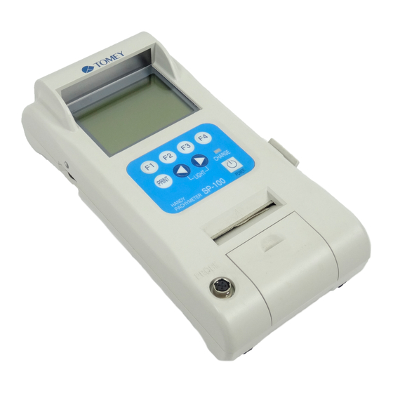
2. NAMES AND FUNCTIONS OF THE COMPONENTS 2.1 Front and Right side of Main Unit A A A A A SCREEN Measurement data and other information can be displayed. B B B B B OPERATING PANEL The keys are located on the panel with various functions. -
Page 16: Operation Keys
2.3 Operation Keys General key assignments are explained in this part. However, other functions are assigned on the same key, depending on the screen. Read each part of the manual carefully in order to understand the key operation completely. A A A A A FUNCTION KEYS Each key works as assigned function shown on (Example) the bottom of the screen. -
Page 17: Operating Procedures
3. OPERATING PROCEDURES 3.1 Safety precautions The Probe must always be disinfected before its use. Never use the Probe, if there is any visible damage on its tip, which may otherwise cause an incorrect measurement or damage the cornea. This instrument is Ophthalmic Medical Device, designed for only skilled operators. -
Page 18: Preparation Before Operation
3.2 Preparation before operation 3.2.1 Connection of accessories a) Connection of Pachymeter Probe Connector of the Probe should be inserted in speci- fied direction. Insert the connector as deep as it sounds "click". Insert the connector A into the connecting terminal B marked "PROBE"... -
Page 19: Optional Components
3.2.3 Optional components Assembling of the Disposal Tip Pachymeter Probe and alternative Probe shapes The Disposal Type Pachymeter Probe (supplied as an optional component) consists of the inner probe, case, fixed ring, and disposal tip. The Probe can be changed in two alternative shapes: (A) with 45 shape and (B) in straight shape, de- pending on the application convenience. -
Page 20: Adjustment And Setting
3.3 Adjustment and Setting 3.3.1 Main power on and screen adjustment Confirm the following items before turning the power on. Make sure the battery is sufficiently charged. If not, con- nect the AC adapter for power supply. (With battery opera- tion and 3 minutes of non operating time, the unit goes into Auto Power off mode and measured data will be lost) Make sure the Probe has been connected. -
Page 21: Startup Display
3.3.2 Startup Display 1) The startup screen is displayed immediately af- ter the power is on. The software version is seen on the screen. (Fig. 1) (Fig. 1) 2) The ultrasound velocity, set for measurement, is displayed. (Fig. 2) (Fig. 2) 3) The unit calibrates the probe automatically. - Page 22 6) Check the connection of the Probe and the Probe tip, then press the " " to recalibrate the Probe. (Fig. 6) When error appears in the screen, go to "6. TROUBLE-SHOOTING" for the solution. When "ERROR" repeatedly appears, contact TOMEY representative. Adjustment and Setting...
-
Page 23: Screen Contents
3.3.3 Screen Contents a) Pachy screen A The eye to be measured Either left or right eye, to be measured, is selected on this part of the screen. B Measurement data The data, taken by the unit will be listed. C Average Average value of the listed data will be displayed. - Page 24 b) Measurement screen A The eye to be measured Either left or right eye, to be measured, is se- lected on this part of the screen. B Measurement data The data, taken by the unit will be listed. While taking measurement, the screen automatically changes and shows large size measuring data.
-
Page 25: Measuring Conditions
3.3.4 Measuring conditions The following measuring conditions have been set, when turning the power on. Eye to be measured: Right eye (OD) Corneal ultrasound velocity: Last value, when it is turned off. a) Input Patient ID and name Please refer to "3.9 Data Management with TOMEYLink (Electronic Medical Record Support System)"... - Page 26 3) Press " " or " " keys to move Cursor I to the figures or letters, you wish to input. (Fig. 3) Then, press SEL G to enter selected character. 4) Press F1 key E to switch over input mode be- (Fig.
- Page 27 b) The eye to be measured Select Right eye or Left eye, to be measured. Press F1 key A to switch over Right and Left dis- play. c) Corneal ultrasound velocity Ultrasound Velocity can be changed by going into setting Menu. Please refer to "3.7.3 c) corneal Ultra- sound Velocity (VELOCITY)"...
-
Page 28: Preparation For Measurement
Be sure the tip of the Probe is dry and free from any water, before calibrating probe. In case of using the disposal tip Probe, the disposal tip is automatically detected by SP-100. Therefore, no measure- ment can be made without calibrating the Probe. 1) This instrument automatically calibrates the Probe, when the power is turned on and the probe is plugged. -
Page 29: Operation Check
3.4.2 Operation Check The test piece included in the accessory box is supplied for checking the operation of the instru- ment. The measurement result varies, depending on room temperature and other factors. The in- strument cannot test its accuracy by measuring this test piece. -
Page 30: Measurement
3.5 Measurement The Probe should always be disinfected before its use. The disposal tip should be disinfected before its use. Do not use the Probe with its tip damaged. This causes inaccurate measurement as well as the corneal damage for patients. The corneal ultrasound velocity has direct influence on measurement results. -
Page 31: Single Measurement
3.5.1 Single measurement a) Measuring procedures 1) Place the probe perpendicularly to the corneal surface, where the thickness needs to be taken. 2) When the measuring conditions meets a cer- tain level, the instrument automatically starts taking measurement (Fig.1). The instrument makes beep, when measurement has been taken into the unit. -
Page 32: Delete Each Data Reading
3.5.2 Delete Each Data Reading When the data is once deleted, it can never be re- called and the deleted data will be lost. Please pay special attention, not to delete necessary measure- ments. 1) Press F3 key A on Pachy screen (Fig. 1) to change screen into EDIT (Fig. -
Page 33: Delete Data (Eye By Eye Or Patient By Patient)
3.5.3 Delete Data (Eye by eye or patient by patient) When the data is once deleted, it can never be recalled and the deleted data will be lost. Please pay special attention, not to delete necessary measurements. a) Delete Data of one eye (Retaking measurements of the same eye) Delete all data on screen. - Page 34 b) Delete Data of both Right and Left Eye including patient information (Ready for new patient measurement) Delete all the data on both eyes, as well as Patient ID and name. Press F4 key A on pachy screen and keep holding it for a while, until the instrument sounds "beep"...
-
Page 35: Printout
3.6 Printout 3.6.1 How to Printout the data Prior to Printout, make sure the proper paper is set correctly and the paper remains suffi- ciently. Please be careful not to cut yourself, when cut- ting the paper by hand. Press the PRINT Key for operation in the Measure- ment Standby Screen (Fig. -
Page 36: Description Of Printout
3.6.2 Description of Printout a) Standard mode A Time/Data B ID number C Patient's name D Corneal Ultrasound Velocity E Type of display data F Eye to be measured G Measured data H Average of measured data I SD(Standard Deviation) of measured data b) Simple mode Patient Name and Breaking Line are out of printout paper on Simple Mode. -
Page 37: Iop Calculation Printout
3.6.3 IOP Calculation Printout a) Standard mode A Time/Data B Patient ID C Patient's Name D Corneal Ultrasound Velocity E Right/Left F Eye to be measured G Measured data H Measured data average I Measured data SD (standard deviation) J Parameter 1 K Parameter 2 L CCT (Central Corneal Thickness) M IOP (Inter Ocular Pressure) -
Page 38: Menu
3.7 Menu 3.7.1 Description of the Screen display A TIME-DATE Date and time are set. B SOUND The sound volume is set. C VELOCITY The corneal ultrasound velocity is set. D DATA SEL The mode of display data is set. E PRINTOUT The print mode is set. -
Page 39: Operation For The Menu Screen
3.7.2 Operation for the MENU Screen 1) Press F3 Key A in the Measurement Standby Screen, to change the screen to the EDIT Screen (Fig. 2). (Fig. 1) 2) Press F4 Key B in the EDIT Screen, to change the screen to the MENU Screen (Fig. 3). (Fig. -
Page 40: Operating Procedures Of The Menu Screen
3.7.3 Operating procedures of the Menu Screen a) Setting of date and time (TIME/DATE) 1) Press " " or " " of the Operation Panel, to align the Cursor to "TIME/DATE". Next press F3 Key A to change the screen to the Time/Date Screen (Fig. - Page 41 b) Sound volume (SOUND) 1) Press " " or " " of the Operation Panel, to align the cursor to "SOUND". Next, press the SEL key A to change the screen to the Sound Volume Setting Screen (Fig. 2). Pressing F4 key B returns the screen to the EDIT Screen.
- Page 42 c) Corneal Ultrasound Velocity (VELOCITY) 1) Press " " or " " of the Operating Panel to align the cursor to "VELOCITY". Next press F3 Key A to change the screen to the Corneal Ultraound Velocity Screen (Fig. 2). Pressing F4 Key B returns the screen to the EDIT Screen.
- Page 43 d) Setting of the type of display data (DATA SELECTION) 1) Press " " or " " of the Operating Panel to align the cursor to "DATA SEL". Next press F3 A and change the screen to the Setting Screen (Fig. 2) for the type of data to be displayed.
- Page 44 e) Print mode 1) Press " " or " " of the Operation Panel, to align the cursor to "PRINTOUT". Next, press F3 key A to change the screen to the Printout Setting Screen (Fig. 2). Pressing F4 key B returns the screen to the EDIT Screen.
-
Page 45: Iop Calculation
3.7.4 IOP Calculation 1) Press F2 A to change the screen to IOP calcula- tion (Fig.2). (Fig. 1) 2) Press F1 B to select either RIGHT/LEFT eye data should be calculated C. (Fig. 2) 3) Press F2 D to change the screen to Tonometry Input (Fig.3). - Page 46 Press F4 H to select the screen to IOP Calcula- tion (Fig.4) (Fig. 4) 3) Press F3 I to change the screen to CCT Input (Fig.5) Average of total measurement data will be automatically input, when there is any data for cal- culation.
- Page 47 5) Press F4 R to change the screen to IOP Calcula- tion (Fig.7) to show calculation result S. 6) Press F4 T to go back to Main MENU (Fig.1). (Fig. 7) 3-31 Menu...
-
Page 48: Sending And Receiving Data
3.8 Sending and receiving data Connect the instrument to the equipment which complies with the IEC06-1 or the IEC950 and of which power source is isolated with the dielectric transformer, by using the serial communication cable. This instrument can send and receive data to and from the external equipment, by using the serial communication cable. -
Page 49: Setting Of Communication Conditions
3.8.2 Setting of communication conditions 1) Press F2 Key A to change the screen to the IN- DEX Screen. (Fig. 2) (Fig. 1) 2) Press F4 Key B to change the screen to the DATA COMMUNICATION Screen. (Fig. 3) (Fig. 2) 3) Use "... - Page 50 4) Press " " or " " of the Operating Panel to set the BAUD RATE. The baud rate is selective from three stages of 9600, 19200, and 38400. Press F1 key E to set as 38400 (default). When F2 Key F is pressed, the screen will be changed as shown in Fig.
-
Page 51: Data Export
3.8.3 Data Export Please refer to "3.9 Data Management with TOMEYLink (Elec- tronic Medical Record Support System)" to send Data to TOMEYLink. 1) Press " " or " " of the Operating Panel in the DATA COMMUNICATION Screen and align the cursor to "SEND". - Page 52 3) "NOW COMMUNICATING" is displayed while data is being sent. (Fig. 4) When F4 Key E is pressed, while data is being sent, the process of sending data is cancelled. (Fig. 4) 4) When data is properly sent, "SENT COM- PLETE!"...
-
Page 53: Data Receiving
3.8.4 Data Receiving Please refer to "3.9 Data Management with TOMEYLink (Elec- tronic Medical Record Support System)" to send Data to TOMEYLink. 1) Make sure before receiving data that there is no data left in the Data Standby Screen. Then, change the screen to the Data Communication Screen (Fig. - Page 54 4) The screen displays "NOW COMMUNICAT- ING" while in the process of receiving data. (Fig. 4) When F4 Key E is pressed, receiving data is cancelled. (Fig. 4) 5) When data is properly received, "RECEIVED COMPLETE!" is displayed.(Fig. 5) Then press F4 F to return the screen to the Data Communication Screen (Fig.
-
Page 55: Data Management With Tomey Link (Electronic Modical Record Support System)
3.9 Data Management with (Electronic Medical Record Support System) SP-100 must be connected with external devices,complied with IEC601-1 Standard or the devices complied with IEC950 Standard and elec- trically insulated by insulation transformer. Please refer to Operation Manual of TOMEYLink (Electronic Medical Record Support System) to setup TOMEYLink soft- ware and LAN adapter (LA-100). - Page 56 Press F4 key E to go back to DATA COMMU- NICATION (Fig.3). (Fig. 4) Patient ID, typed in SP-100 has nothing to do with TOMEYLink Patient ID. TOMEYLink Pa- tient ID will always have priority to register data on TOMEYLink. Please note that the ID on SP- 100 will be ignored.
-
Page 57: Data Sending
(Fig. 7) 3.9.2 Data Sending 1) Press " " or " " button to move cursor to SEND on DATA COMMUNICATION (Fig.1). Press F3 key A to go to DATA SENDING screen (Fig.2). (Fig. 1) 3-41 Data Management with TOMEY Link... - Page 58 (Fig.4). Press F4 key E to cancel sending data. (Fig. 4) 4) When data is properly sent, SENTCOMPLETE! is displayed (Fig.5). Press F3 key F to go back to DATA SENDING screen (Fig.2). (Fig. 5) 3-42 Data Management with TOMEY Link...
-
Page 59: Battery
3.10 Battery Please use the battery only specified for SP-100. The use of wrong type may cause Heating/Fire/Explosion of the battery and main unit. After the battery has been charged, pull off the AC Adapter from the instrument. If the... -
Page 60: Low Battery Warning
3.10.2 Low Battery Warning 1) When capacity of the battery becomes low A, SP-100 screen starts blinking and beeping (Fig.1). Under this condition, the unit shuts down after 10 minutes of non-operating time, automatically. Within 10 minutes, the battery needs to be charged or measured data will be lost. -
Page 61: Charge Indicator
3.10.3 Charge indicator The charge indicator A on the Operating Panel lights up, while the battery is being recharged. When the charge indicator light goes off (Full Charged), discon- nect the AC Adapter from the instrument. 3.10.4 How to Install / Uninstall Battery Please pay special attention not to disconnect the battery cable. -
Page 62: Lifetime Of Rechargeable Battery
3.10.5 Lifetime of rechargeable battery The battery, built-in the instrument, keeps 85% of its capacity even after 500 times recharge and discharge under 25 degree Celsius room temperature. Since any battery has its lifetime, replace with new battery, when its discharging time is getting shorter than it used to be. 3.10.6 Expected operating time of hours The battery enclosed in the instrument is serviceable for the fol-... -
Page 63: Reference Technical Information
4. REFERENCE TECHNICAL INFORMATION 4.1 How to calculate corneal thickness The corneal thickness is calculated in the following calcula- tion by using the converted sound velocity in the cornea. Tc = where, Tc:Corneal thickness V: Converted sound velocity in the cornea t: Measuring time 4.2 Acoustic Output 4.2.1 MI (Mechanical Index) - Page 64 This page is left intentionary blank.
-
Page 65: Maintenance And Inspection
Tomey, not to a product whose serial number or batch number is removed, altered or effaced. -
Page 66: Routine Maintenance
5.2 Routine maintenance 5.2.1 Measurement Probe Be sure to hold the connector of the Probe cable to disen- gage the Probe from the instrument. Do not pull the cord itself, which may cause to damage the cord or to ruin its power connection. - Page 67 b) Disinfection For disinfecting of the Probe, immerse the part of the Probe within 15mm from the eye contacting part it in disinfection etha- nol or 0.5% sodium hydrochloride water solution for 10 to 20 minutes and then wash it with distilled water and then dry suffi- ciently.
-
Page 68: Maintenance Of The Main Unit
5.2.2 Maintenance of the Main Unit — Do not use such organic solvents as thinners for cleaning the Main Unit of the instrument. Such organic solvents may cause to damage the surface of the Main Unit. Do not pull the power cord with an undue force. Care is to be taken not to touch the Probe connecting ter- minals. -
Page 69: Replacing Of The Printer Paper
5.3 Replacing of the printer paper Replace the printing paper when the red lines appear on the both sides of the roll paper, according to the following procedure. Care is to be taken not to damage your hand with the paper cutter, when opening and closing the Printer Cover. -
Page 70: Storage
5.4 Storage Store the instrument in a place where it is free of water, moisture and chemicals. Do not store the instrument in a place where it is subjected to high temperature and high humidity and to any adverse influences that the instrument may be exposed to dust, salts, and/or sulfur. -
Page 71: Troubleshooting
6. TROUBLESHOOTING Before presuming the instrument is disordered, check the following items. If the following items do not correct the malfunction, consult with your local rep- resentative for countermeasures. Do not remove the outer cover of this instrument while in operation, which will otherwise expose you to the direct high voltage. - Page 72 No information is displayed in the Monitor Screen. The Auto Power-off Function is in actuation, which automati- Cause 1 cally turns the power of the instrument off if it does not con- tinue operation for longer than 3 minutes. Turn the power for the instrument on. Remedy The switch for maintenance which is located at the rear side Cause 2...
- Page 73 The Clock in the screen is in cease. The INDEX Screen displayed after data measurement has Cause 1 been made is shown. In case the INDEX Screen displayed after data measure- Remedy ment has been made is shown, the date and time when data measurement was made are displayed in the screen.
- Page 74 <Measuring Function> "PROBE ERROR!" is displayed in the calibration of the Pachymeter Probe given when the power is turned on. The connection of the Pachymeter Probe is not proper. Cause 1 Properly connect the Probe, in accordance with the pro- Remedy cedure specified in "3.2.1 a Connecting of the Pachymeter Probe".
- Page 75 The Pachymeter Probe has not been properly calibrated. Cause 5 Clean the tip of the Probe and re-calibrate the Probe in the Remedy procedure specified in "3.4.1 Calibrating of the Pachymeter Probe" or once turn the power off, next reboot the instru- ment, and the calibrate the Probe.
- Page 76 Monitor sounds do not stop. Measurement data is taken when measurement is not in process. The tip of the Pachymeter Probe is wet with water. Cause 1 Remedy Remove the water from the tip of the Probe. Monitor sound is not made. The sound volume is set as OFF.
-
Page 77: Spare Parts And Optional Parts
The following spare parts and optional parts are available upon ordering to your Tomey local distributor or representative. 7.1 Spare parts Printer paper Specify your order article as "Printer paper for SP-100 " when you order. 7.2 Optional parts Pachymeter Probe (Standard Probe) Specify your order part as "Standard Pachymeter Probe... - Page 78 This page is left intentionary blank.
-
Page 79: Specifications
8. SPECIFICATIONS 8.1 Specifications 8.1.1 Measuring function Default Converted Ultrasound Velocity and Setting Range Corneal Ultrasound Velocity : 1,640 m/s (1,400 to 2,000 m/s) Measuring range Corneal thickness Standard Probe : 150 to 1,200µm Disposal tip type Probe : 150 to 1,200µm Instrument accuracy Measuring accuracy : ±5µm... -
Page 80: Ultrasound Energy And Other Information
8.2 Ultrasound energy and other information 8.2.1 Influences of ultrasound energy on the human body SP-100 Pachymeter is exclusively designed and built for ophthalmic use. Do not use the instrument for any purposes other than ophthalmic use. SP-100 Pachymeter, exclusively designed and built for ophthalmic pachymeter purpose, is set at very weak ultrasound energy ap- propriate for ophthalmic application. - Page 81 PD : the pulse duration PRF : the puls repetition frequency EBD : the entrance beam dimensions for the azimuthal and elevational planes Acoustic Output Report (IEC60601-2-37) Index label Non-scan(Aaprt 1cm Maximum index value 0.15 2.005 10 [Mpa] 0.44 P [mW] 0.0211 Min.of [P (zs),Ita, (zs)] Associated...
-
Page 82: Noise Generation
DISTANCE FROM THE SOURCE TO A SPECIFIED POINT zb : DEPTH FOR TIB zbp : BREAK-POINT DEPTH zs : DEPTH FOR TIS 8.3 Noise Generation This instrument makes monitoring sounds at the following occa- sions. When turning the power on. When Printout When operating various keys and buttons When taking measurement (such as taking data) - Page 83 Table 201 The SP-100 is intended for use in the electromagnetic environment specified below. The customer or the user of the SP-100 should assure that it is used in such an environment. Emissions test Compliance Electromagnetic environment - guidance...
- Page 84 Guidance and manufacturer's declaration - electromagnetic immunity Table 202 The SP-100 is intended for use in the electromagnetic environment specified below. The customer or the user of the SP-100 should assure that it is used in such an environment. Immunity test...
- Page 85 If the measured field strength in the location in which the SP-100 is used exceeds the applicable RF compliance level above, the SP-100 should be observed to verify normal operation. If abnormal performance is observed, additional measures may be necessary, such as reorienting or relocating the SP-100.
- Page 86 SP-100 Table 206 The SP-100 is intended for use in an electromagnetic environment in which radiated RF disturbances are controlled. The customer or the user of the SP-100 can help prevent electromagnetic interference by maintaining a minimum distance between portable and mobile RF communications equipment (transmitters) and the SP-100 as recommended below, according to the maximum output power of the communications equipment.
-
Page 87: Index
9. Index Disinfection 3-2, 5-3 INDEX disposal 5-6 Disposal Tip 3-3 Disposal tip 3-14, 7-1 AC Adapter 2-1, 3-2, 3-39, 6-1 EDIT 3-7, 3-15, 3-16, 3-17, 3-26 AC adapter terminal 1-4 EOG 5-3 AC power adapter 1-5 ERROR 3-6 Acoustic Output 4-1 EXIT 3-21 Auto Measurement Function 3-14 Explosion 3-39... - Page 88 SOUND 3-21, 3-24 sound volume 6-6 NEW 3-7 Spare parts 7-1 NOW COMMUNICATING 3-32, 3-34, 3-36, 3-38 Specifications 8-1 Standard Probe 7-1 Sterilization 5-3 OPERATING PANEL 2-1 STOP BIT 3-30 Optional parts 7-1 Storage 5-6, 8-4 Symbols 1-4 Pachy 3-8, 3-21 Pachy screen 3-7 test piece 1-3, 3-13 Pachymeter Probe 3-2...
- Page 89 Fax: +81 52-561-4735 EC-representative Tomey GmbH Am Weichselgarten 19a 91058 Erlangen GERMANY Tel: +49 9131-77710 Fax: +49 9131-777120 AUTHORIZED TOMEY SERVICE CENTERS Headquarters, Pacific rim Tomey Corporation 2-11-33 Noritakeshinmachi Nishi-ku, Nagoya 451-0051 JAPAN Tel: +81 52-581-5327 Fax: +81 52-561-4735 Europe...
- Page 90 0123 ID: 0410...
Need help?
Do you have a question about the SP-100 and is the answer not in the manual?
Questions and answers