
Related Manuals for AFL M710 Series


Summary of Contents for AFL M710 Series
- Page 1 Test & Inspection M710-Series OTDRs with LinkMap ® User’s Guide www.AFLglobal.com, +1 (800) 321-5298 or +1 (603) 528-7780...
-
Page 2: Table Of Contents
Job Selection from a Test Mode . . . . . . . . . . . . . . . . . . . . . . . . . . . . . . . . . . . . . . .32 ©2016, AFL, all rights reserved . M710-00-1000 Revision 1B, 2016-04-19... - Page 3 Table of Contents Opening Test Results for Review . . . . . . . . . . . . . . . . . . . . . . . . . . . . . . . . . . . . . .33 OTDR Testing .
-
Page 4: Otdr Software Options
Event Analysis Technology ® The M710 OTDRs utilize AFL’s industry leading TruEvent technology to provide a new level of accuracy and reliability in event analysis . Events on a fiber include connectors, splices, optical splitters and macro-bends . To accurately locate an event, OTDRs need to find its location, identify event type, measure reflectivity and loss . -
Page 5: Hardware Overview
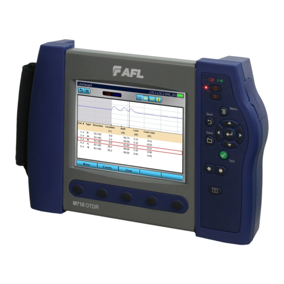
Hardware Overview Controls, Ports, and Features Top Panel View Front Panel View Ref Control/Feature Description OTDR ports These are CLASS I LASER outputs VFL port This is a CLASS II LASER output . Do not stare into beam . The VFL (visual fault locator) port is a 650 nm (red) laser . Used for short-range fault-location . - Page 6 Hardware Overview Controls, Ports, and Features Back Side View Left Side View Right Side View Ref Control/ Description Feature Power port This is interface for the AC power adapter/charger . Mini-USB This port may be used to connect OTDR to a USB host port on PC with the function port supplied cable .
-
Page 7: Front Panel Keys And Indicators
Hardware Overview Front Panel Keys and Indicators The use of each key is summarized in the table below . Symbol Key/Indicator Function AC Adapter/ This indicator Illuminates when the AC adapter/charger Charger is connected: indicator Red light ON indicates that battery is charging . Green light ON indicates that battery is fully charged . - Page 8 Hardware Overview Front Panel Keys and Indicators Symbol Key/Indicator Function Menu key Press to access the Main Menu . The Menu Icon must be displayed on the top bar for the key to perform the action . If you are at the top level the Menu key will be disabled .
-
Page 9: User Interface Overview
User Interface Overview Main Menu Two types of modes are available from the Main Menu as follows: TEST MODES: OTDR, OPM, DFS Used to perform OTDR, OPM and Inspection To select the desired mode tests . • Tap the appropriate Touchscreen icon . •... -
Page 10: Test Modes Settings Summary
User Interface Overview Test Modes Settings Summary Real-Time Full Auto Expert (Real-time OTDR) (Automatic (Optical Power (Manual OTDR) OTDR) Meter) Fiber type, launch and receive test cord lengths Wavelength, range, pulse-width, resolution Wavelength Automatic or Averaging time Units (dB/dBm) Automatic or default settings default settings Event thresholds... -
Page 11: Selecting Operating Mode From The Main Menu
User Interface Overview Selecting Operating Mode from the Main Menu Mode Icon Description Full Auto This is the recommended mode for users who are not familiar with OTDR OTDR operation . In the Full Auto mode, OTDR parameters such as Range, Pulse Width, and Averaging Time are set automatically . Full Auto Tests are done at all available wavelengths and always include an Event Table and Summary page . -
Page 12: Display Features
User Interface Overview Display Features Ref Description Page header - Displays page name and test status . Battery status icon: Green - fully charged Red - discharged Charging - AC connected Fully Charged - AC connected Main Menu touch key . Back touch key . -
Page 13: Test Pages Tabs Legend
User Interface Overview Test Pages Tabs Legend When a test mode (OTDR or OPM) is enabled, your OTDR will display the ‘Home’ screen of the enabled test mode . • Use Tab keys to change test pages/screens available for the enabled test mode . Full Auto/Expert OTDR mode Real-Time OTDR mode 1 . -
Page 14: General Settings
General Settings arrows to highlight the desired parameter Press to select distance units of Press key to display submenu, measure . which allows the selection of available date/time/numbers arrows to toggle the Beeper formatting options . function On/Off . Press key to display submenu, arrows to define the which allows the selection of... -
Page 15: New Job Utility
New Job Utility New Job Overview The New Job utility mode is available for creating new jobs (setting up a file structure and defining the fiber under test location: Drives, Folders, Jobs, Routes End Locations, Cables, Test Equipment Location, and Operators) . The New Job utility menu is accessed from the Main Menu by tapping the New Job Touchscreen icon or by pressing the New... -
Page 16: New Job Creation
New Job Utility Mode New Job Creation Folder, Job, End 1, End 2, and Cable parameters: arrows to toggle between the End 1 and End 2 options . • Highlight the desired parameter . • Use arrows to scroll through the lists of existing/previously created names . -
Page 17: Otdr Test Settings
OTDR Test Settings Full Auto Mode Settings Core Settings Full Auto mode settings are common for all OTDR Test modes and will be referred to as Core Settings . Parameter Definition Test Port This parameter indicates that a multimode or single-mode laser is used to generate an OTDR trace . -
Page 18: Expert Mode Settings
OTDR Test Settings Expert Mode Settings In addition to Core Settings (see “Full Auto Mode Settings” on page 17), the Expert test mode allows you to set the Wavelength, Range, Pulse Width, Averaging Time, and Resolution parameters . Setup - Auto Setup - Auto Once If set to Auto, OTDR sets Range, Pulse If set to Auto Once, OTDR sets Range,... -
Page 19: Real-Time Mode Settings
OTDR Test Settings Expert Mode Settings: Setup - Manual (continued) Note: The Range, Pulse Width, and Averaging Time parameters are user-selectable if the Setup parameter is set to Manual . Parameter Description Range The Range parameter determines the distance range of the full (unzoomed) trace . -
Page 20: Event Settings
Event Settings The Event Settings Menu is available from either Full Auto or Expert test mode . Setup Parameters Available in Full Auto Mode In Full Auto OTDR test mode these parameters are set as follows: Parameter Option Description Events Auto An Event Table is calculated for every test . -
Page 21: Setup Parameters Available In Real-Time Mode
Event Settings Setup Parameters Available in Expert Mode (continued) Parameter Option Description Default View default values (see page 23 for details) and turn Event Pass Thresholds On/Off (Threshold set to default values) Pass/Fail Thresholds User Values may be adjusted within allowed limits (see page 23 details) . -
Page 22: Navigating Through Event Setting Menu
Event Settings Event Setting menu is enabled either in Full Auto or Expert OTDR test mode . From the Full Auto, Expert, or Real-Time test mode perform the following: • Use Tab Keys to access the Event Settings page . •... -
Page 23: Pass/Fail Settings
Event Settings Pass/Fail Settings Event Thresholds Chart Threshold Min Value Default Value Max Value (dB) (dB) (dB) Event Loss 0 .02 0 .10 1 .0 Event Reflectance -65 .0 -65 .0 -35 .0 Event End 1 .0 3 .0 25 .0 Event Pass Thresholds Threshold Min Value... -
Page 24: Opm Test Settings
OPM Test Settings OPM Home Page Indicators This field displays test This field displays the current Displays the currently readings: OPM test mode: selected or detected Wave ID - receiving wavelength(s) . • Measured Insertion Loss values in dB or measured wavelength ID’d light . -
Page 25: Soft Keys/Touchscreen Icons
OPM Test Settings Soft Keys/Touchscreen Icons OPM Live Mode OPM Saved Mode Note: The current function of each soft key is indicated by an icon or label on the Touchscreen . If you prefer using the Touchscreen, tap the appropriate icon or label . Icon Function Wavelength... -
Page 26: Results Manager
Results Manager Results Manager Overview Note: See section “New Job Creation” on page 16 for a simplified means of creating new jobs . The Results Manager menu is accessed from the Main Menu by tapping the Results Touchscreen icon or pressing the Results soft key . •... -
Page 27: Results Manager "File Tree" Structure
Results Manager Results Manager “File Tree” Structure Test results are saved as files that are stored in Cable folders . Cable folders are organized into Route, Job, and Drive folders as shown below . • Use arrows to navigate up/down the list of folders and files . •... -
Page 28: Cut/Copy/Paste Features
Results Manager Cut/Copy/Paste Features Using Copy/Cut/Paste features, stored test results can be moved to other locations on the OTDR Internal drive or to a USB drive . To Copy/Cut/Paste Stored Test Results Note: To copy the test data and place elsewhere (the original test data remains in its current location), choose the Copy feature . -
Page 29: Rename Feature
Results Manager Cut/Copy/Paste Features 4 . Press the Paste soft key (if the Paste soft key label is displayed on the soft keys bar) . Note: The availability of this command depends on the test result selection . • If the Paste soft key label is not displayed on the soft keys bar, press the Tools key (where applicable) to display the Tools menu . -
Page 30: Job Creation In Results Manager
Results Manager Job Creation in Results Manager Note: See “New Job Creation” on page 16 for a simplified means of creating New Jobs . 1 . From the Results Manager page, use arrows to highlight the desired Drive where test results will be saved . 2 . -
Page 31: Job Selection From Results Manager
Results Manager Job Selection from Results Manager To select an existing job from the Results Manager utility: 1 . Highlight the desired cable A in the Job/Route to be tested . 2 . Press the Open soft key B to select . 3 . -
Page 32: Job Selection From A Test Mode
Results Manager Job Selection from a Test Mode A Job is selected from the Job Settings page, which is accessed from each test mode . Within each test mode, use tab keys to select tab and display the Job Settings page . From the Job Settings page, use arrows to highlight Cable . -
Page 33: Opening Test Results For Review
Opening Test Results for Review • Access Results Manager from the Main Menu by pressing the Results soft key A . • Use the arrows to navigate up/down the list of folders/files . • Use the arrows to expand/contract the selected Drive/Folder/Job/Route/Cable . •... -
Page 34: Otdr Testing
OTDR Testing Running OTDR Tests Press to start or stop an OTDR Test . The OTDR page header will change to display test progress and the displayed test results status . Page header Initializing A header is displayed when the test started with the Front Panel Check/First Connector Check features enabled . -
Page 35: How To Perform An Otdr Test
OTDR Testing How to Perform an OTDR Test • Press Menu to display the Main Menu . • Select desired test mode (Full Auto, Expert or Real-Time) . • Review settings using the tab keys . Home Test Settings Event Settings Job Settings •... -
Page 36: How To Save An Otdr Test
OTDR Testing How to Perform an OTDR Test LinkMap Trace page Event Table Summary page Job Info . page • To change any Job settings, go back to New Job and edit if you want to apply to the entire Job . Adjustments made on the Job Settings page will only apply to current unsaved trace(s) . -
Page 37: Front Panel And First Connector Check
OTDR Testing Front Panel and First Connector Check The Front Panel and First Connector Check features are available in all OTDR test modes and enabled in the Events Setting Menu (see section “Event Settings” on page 20 for details) . When enabled, these features provide an indication of the quality of the connections at the OTDR front panel and connection between the launch cable and the fiber under test allowing the user to minimize capturing poor test results . -
Page 38: Otdr Test Results Viewer
OTDR Test Results Viewer Trace Viewer Features Ref Feature Description Trace This is a graph of insertion loss vs . distance . The vertical axis shows loss in dB . The horizontal axis shows distance in user-selected distance units . LSA adjust lines Available for LSA Loss Methods, not Two Point measurements . - Page 39 OTDR Test Results Viewer Trace Viewer Features Ref Feature Description Test status Displays test status labels as follows: • Testing - indicates test in progress • Stopped - test is interrupted • Not Saved - the displayed test results are not saved •...
-
Page 40: Linkmap Viewer Features
OTDR Test Results Viewer LinkMap Viewer Features Ref Feature Description Test status Displays test status labels as follows: • Testing - indicates test in progress • Stopped - test is interrupted • Not Saved - the displayed test results are not saved •... - Page 41 OTDR Test Results Viewer LinkMap Viewer Features Ref Feature Description Event icon Event icons may be green (pass), red (fail), or blue (Information only, not evaluated for Pass/Fail ) . Pass/Fail is based on event loss and reflectance thresholds configured by the currently selected Pass/Fail Event Thresholds Same color as event pass/fail status .
-
Page 42: Event Icons And Types
OTDR Test Results Viewer Event Icons and Types Event Icon Event Type Reflective event (i .e . connector) Pass Reflective event (i .e . connector) Fail Reflective event (information only, not evaluated) Closely spaced event Pass Closely spaced event Fail Closely spaced (information only, not evaluated) Macrobend Pass Macrobend Fail... -
Page 43: Soft Keys Definitions And Functions
OTDR Test Results Viewer Soft Keys Definitions and Functions Soft Key Description and function For multiple-wavelength test, press this key to toggle between available results . See section titled “Wavelength Selection Menu In OTDR Pages” on page 44 for details . •... -
Page 44: Wavelength Selection Menu In Otdr Pages
OTDR Test Results Viewer Wavelength Selection Menu In OTDR Pages Screen #1 Screen #2 The Wave menu A is accessed by pressing the Wave key . This menu serves two purposes: • Allows the user to select the active wavelength . •... - Page 45 OTDR Test Results Viewer Wavelength Selection Menu In OTDR Pages To enable/disable multi or single trace display: • Use arrows to select the desired display option as follows: – Select Show All option B to display multiple wavelength traces with the currently selected wavelength trace on top .
-
Page 46: View Results In Trace Page
OTDR Test Results Viewer View Results in Trace Page 1 . Press Wave to display the Wave menu A and select the desired wavelength to be displayed (see “Wavelength Selection Menu In OTDR Pages” on page 44 for details) . 2 . -
Page 47: View Results In Event Table
OTDR Test Results Viewer View Results in Event Table Event Table and Summary Results are generated together . To generate the Event Table and Summary Results, set Mode to Full Auto or set Mode to Expert and Events (Event Settings) to Auto . To View test results in the Event Table: 1 . -
Page 48: Event Table Data
OTDR Test Results Viewer Event Table Data Ref . Description Event Number Pass - or Fail - status Event Type 4 Event Direction 5 Event Location 6 Reflectance (dB) 7 Loss (dB) 8 Cumulative Loss (dB) Event Icons and Types Event Icon Event Type Event Icon... -
Page 49: How To Switch Test Data Column Sets In Summary Page
OTDR Test Results Viewer – End 1 -> 2 to display the trace taken from End 1 . – End 2 -> 1 to display the trace taken from End 2 . 4 . Press key to confirm selection and exit View menu . 5 . -
Page 50: Re-Calculate Events
OTDR Test Results Viewer Re-Calculate Events 1 . From the Event Table or Summary Results page, press Events to display the Events menu A . 2 . Use arrows to select the Re-Calc option B . 3 . Press key to confirm selection . -
Page 51: Full Auto Mode: Fault Locating
Full Auto Mode: Fault Locating 1 . Select Full Auto mode . 5 . Select Launch Cable: 1 km, 500 m, 150 m, None, User . 2 . Clean and Connect launch cable . 6 . In General Settings: Set Distance Units: m, ft, 3 . -
Page 52: Opm Operation - Testing Multimode/Single-Mode Links
13 . Mate the free ends of the transmit and receive jumpers using an appropriate adapter . 14 . Verify that the insertion loss of this mated connector pair is under 0 . 7 5 dB, the maximum allowed by the TIA and ISO (AFL recommends 0 .4 - 0 .5 dB typical), as follows:... -
Page 53: Step Iii - Measure Link Insertion Loss
OPM Operation - Testing Multimode/Single-mode Links Step II - Verify Test Jumpers • Observe the displayed loss level . This is the mated connector pair insertion loss of the test jumpers in dB . • If the insertion loss is not acceptable, disconnect the transmit and receive jumpers at the adapter, clean the free ends of both test jumpers and repeat steps 12 and 13 . -
Page 54: Text Editor
Text Editor The user can select the keyboard style in the General Settings . Alphanumeric keyboard Qwerty keyboard Editable text field . Editable text field . Press when done . Press when done . Touch Pad (tap with stylus or use Arrows Touch Pad (tap with stylus or use and Enter keys) . -
Page 55: Transferring Files
. 2 . Navigate to the test result you want to transfer . In our example: the ‘AFL’ job A . 3 . Press the Copy To USB key B . 4 . At the Copy screen C , press OK D to confirm the copy task . -
Page 56: Recommended Accessories
“does not include loss of last connector” or “Does not include Receive Cable” in the PC analysis and reports . Fiber Rings may be used as Launch and Receive cables . Fiber Rings with a variety of lengths and connector styles are available from AFL . Fiber Optic Test Cables and Jumpers Selection Chart... -
Page 57: Cleaning Tips
CAUTION! Never view a live fiber . Laser radiation is harmful to eyes . Follow your company’s approved cleaning procedures . AFL recommends cleaning test cables using a Cletop cassette cleaner or a One-Click Cleaner . Cleaning the OTDR and VFL optical ports without removing the adapters CAUTION! Before conducting the following procedures be sure to have the OTDR turned OFF . - Page 58 Cleaning the optical ports with adapters removed Cleaning the Exposed Ferrule or the OPM port Use lint-free optical cleaning wipes such as AFL FiberWipes and optical quality cleaning fluid such as AFL FCC2 connector cleaning fluid . Note: If using isopropyl alcohol (IPA), be sure to use 99% pure IPA that has not been contaminated .
-
Page 59: Faqs
FAQs Can I save traces for viewing later? Yes . There is a dedicated Save key . In the Main Menu “File tab”, set up the location/folder (Internal or USB) to save the file, the file naming format, and fiber number . The fiber number will automatically increment after each trace is saved . -
Page 60: Recharging Batteries
AFL recognizes many customers prefer annual calibration for all their Test and Inspection instruments . To support our customers AFL offers pre-paid calibration plans for AFL Test & Inspection products . Pre-paid plans allow customers to factor two annual calibrations into initial purchase order ensuring they will have a calibrated tool for three years without the hassle (and potential delay) of seeking internal purchase approval for necessary future calibrations . - Page 61 Calibration and Repair Facilities AFL has an authorized calibration/repair facility for AFL products in the USA, Europe and Asia Pacific . Please contact customer service for a return authorization number prior to sending your AFL test equipment in for repair or calibration .
-
Page 62: Limited Warranty
(1) one year warranty period . Any product that is found defective within the warranty period, will (at the discretion of AFL) be repaired or replaced . Warranty will be voided if the product has been repaired or altered by other than an authorized AFL repair facility or which have been subject to misuse, negligence, or accident . -
Page 63: Safety Information
CAUTION! Do not run any tests or perform functions that activate an OTDR laser unless fiber is attached to the corresponding OTDR port . NOTICE! AFL OTDRs contain no user serviceable parts . Except for changing batteries and cleaning optical ports, these instrument must be returned to AFL or authorized agents for repair and calibration . - Page 64 Test & Inspection Thank you for choosing AFL Test & Inspection! www.AFLglobal.com, +1 (800) 321-5298 or +1 (603) 528-7780...
Need help?
Do you have a question about the M710 Series and is the answer not in the manual?
Questions and answers