
Related Manuals for Waters ACQUITY RDa


Summary of Contents for Waters ACQUITY RDa
- Page 1 ACQUITY RDa Detector Overview and Maintenance Guide 715005003 Copyright © Waters Corporation 2021 Version 04 (Previously released as Revision C) All rights reserved...
-
Page 2: General Information
This document is believed to be complete and accurate at the time of publication. In no event shall Waters Corporation be liable for incidental or consequential damages in connection with, or arising from, its use. For the most recent revision of this document, consult the Waters website (www.waters.com). -
Page 3: Contacting Waters
We seriously consider every customer comment we receive. You can reach us at tech_comm@waters.com. Contacting Waters Contact Waters with enhancement requests or technical questions regarding the use, transportation, removal, or disposal of any Waters product. You can reach us via the Internet, telephone, fax, or conventional mail. Contact method Information www.waters.com... -
Page 4: Safety Considerations
Safety considerations Some reagents and samples used with Waters instruments and devices can pose chemical, biological, or radiological hazards (or any combination thereof). You must know the potentially hazardous effects of all substances you work with. Always follow Good Laboratory Practice (GLP), and consult your organization’s standard operating procedures as well as your local... - Page 5 the LC. You must connect the Stop Flow cable to the LC correctly so that if the gas supply fails, solvent does not flood the mass spectrometer's source and damage the device. High temperature hazard Warning: To avoid burn injuries, exercise care when handling the components of the source enclosure heated to high temperatures.
- Page 6 Do not dispose of the instrument or return it to Waters for repair until the authority responsible for approving its removal from the premises specifies the extent of decontamination required and the level of residual contamination permissible.
-
Page 7: Electrical Power Safety Notice
Electrical power safety notice Do not position the device so that it is difficult to disconnect the power cord. Equipment misuse notice If equipment is used in a manner not specified by its manufacturer, the protection provided by the equipment may be impaired. Safety advisories Consult the "Safety advisories"... -
Page 8: Audience And Purpose
For compliance with the Waste Electrical and Electronic Equipment Directive (WEEE) 2012/19/EU, contact Waters Corporation for the correct disposal and recycling instructions For indoor use only No pushing... -
Page 9: Intended Use Of The Acquity Rda Detector
Intended use of the ACQUITY RDa Detector The ACQUITY RDa Detector is a time-of-flight mass detector with an ESI source, and is intended for use as an analytical tool. It provides accurate mass data with minimal interaction from the user. The LC/MS ESI instrument is not intended for use in diagnostic applications. -
Page 10: Emc Emissions
Dispose of Waters instrumentation products in accordance with applicable requirements and best practices as described below. • Follow appropriate procedures for flushing the instrument’s fluid paths of any hazardous samples or solvents. -
Page 11: Table Of Contents
ISM classification: ISM group 1 class A..................ix EMC emissions..........................x Safe disposal............................x 1 ACQUITY RDa Detector Overview................15 1.1 ACQUITY RDa Detector Front Panel Overview................16 1.2 Instrument display.......................... 17 1.3 Fluidics System..........................19 1.3.1 Fluidics system........................19 1.4 ACQUITY RDa Detector leak sensors................... 20 August 20, 2021, 715005003 Ver. - Page 12 2.1 Software and data system......................21 2.1.1 Calibrating and tuning the instrument................... 21 2.1.2 Acquisition Modes.........................23 2.1.3 ACQUITY RDa Detector health system................23 2.2 Leaving the instrument in Power Save mode.................25 2.3 Power-cycling the ACQUITY RDa Detector................... 25 3 Maintenance procedures..................26 3.1 Maintenance schedule........................
- Page 13 A.1.1 Specific warnings........................67 A.2 Notices............................69 A.3 Bottles Prohibited symbol......................69 A.4 Required protection........................69 A.5 Warnings that apply to all Waters instruments and devices............70 A.6 Warnings that address the replacement of fuses................74 A.7 Electrical symbols.......................... 75 A.8 Handling symbols...........................76 B Preparing the system for operation................ 78 B.1 Rear panel connections.........................
- Page 14 C Specifications......................85 C.1 Physical specifications........................85 C.2 Environmental specifications......................85 C.3 Electrical specifications........................86 C.4 Input Output specifications......................86 D External connections....................88 D.1 Mass detector: external wiring and vacuum connections.............. 88 D.2 Connecting the Edwards oil-filled backing pump................90 D.2.1 Making the electrical connections to the rotary backing pump..........93 D.3 Connecting to the nitrogen gas supply..................
-
Page 15: Acquity Rda Detector Overview
1 ACQUITY RDa Detector Overview The ACQUITY RDa Detector is a time-of-flight mass detector with an ESI source, and is intended for use as an analytical tool. It provides accurate mass data with minimal user interaction. The ACQUITY RDA Detector is a SmartMS-enabled mass detector with an automatic setup routine that ensures consistent results and continuously monitors and maintains performance, providing confidence in your data. -
Page 16: Acquity Rda Detector Front Panel Overview
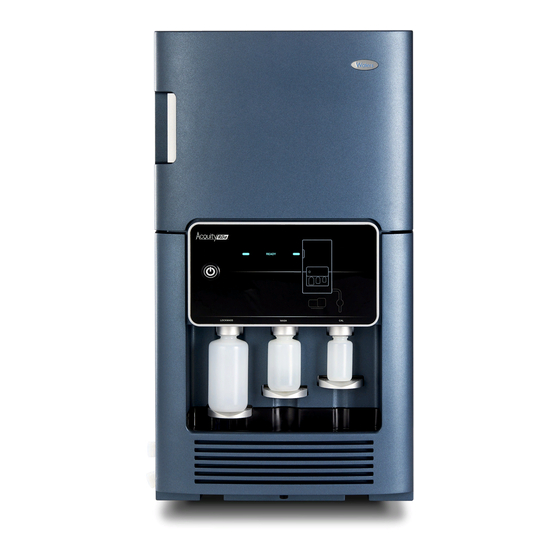
1.1 ACQUITY RDa Detector Front Panel Overview Figure 1–1: ACQUITY RDa with the instrument door closed Instrument display Calibration reservoir bottle Wash reservoir bottle Air filter Lock mass reservoir Power button bottle Instrument door handle August 20, 2021, 715005003 Ver. 04 (Previously released as Revision C) -
Page 17: Instrument Display
Leak sensor Source Air filter 1.2 Instrument display The symbols on the ACQUITY RDa Detector's front panel display the current operating status of the system and its components: • Initializing • Ready August 20, 2021, 715005003 Ver. 04 (Previously released as Revision C) - Page 18 • Running • Check • Call Service The Initializing LED remains illuminated until instrument setup is complete. When the instrument setup is complete, the status LED changes to Ready and the instrument is ready for use. If the instrument identifies a problem, the status changes to Check and an appropriate icon illuminates.
-
Page 19: Fluidics System
1.3 Fluidics System 1.3.1 Fluidics system Prohibited: To avoid injuries from broken glass, falling objects, or exposure to toxic substances, do not place containers directly on top of the instrument or on its front covers. Instead, use the bottle tray. The divert valve automatically controls the flow of the fluidics in the system, delivering sample directly to the instrument's source in one of the following two ways: •... -
Page 20: Acquity Rda Detector Leak Sensors
The flow state function selects the position of the LC flow. When the fluidics are operating, the flow state is set to waste as the LC flow is diverted to waste. 1.4 ACQUITY RDa Detector leak sensors A leak sensor in the instrument’s drip tray continuously monitors for liquid leaks. If a leak occurs, the instrument detects it and the software stops the LC flow to prevent the loss of sample and any damage to the system. -
Page 21: Preparing For Operation
• Printing reports 2.1.1 Calibrating and tuning the instrument To calibrate and tune the instrument, use the Instrument Setup function on the Acquity RDa tab to define the mass range and polarity settings, and then click Start. August 20, 2021, 715005003 Ver. 04 (Previously released as Revision C) - Page 22 If this happens, the software will guide you on how to complete the calibration. • When transitioning from Power Save mode to Operate mode, Waters recommend that you allow the instrument to stabilize for one hour prior to use.
-
Page 23: Acquisition Modes
If multiple health checks are flagged as problems, they are displayed in a prioritized order. Errors are always presented ahead of Warnings, as Errors require you to contact your Waters service engineer. Once a health check is rectified, the next in priority is displayed until all are resolved. - Page 24 • Warnings - The instrument is in a Check state. Warnings are issues observed by the health system that you can rectify through user maintenance activities. • Errors - The instrument is in an Error state and requires the help of a Waters service engineer. The panel on the instrument displays the words Call Service.
-
Page 25: Leaving The Instrument In Power Save Mode
If the instrument has been in Power Save mode for more than 60 minutes and you transition to Operate mode, Waters recommend that you allow the instrument to stabilize for at least one hour before you calibrate the instrument or run any samples. -
Page 26: Maintenance Procedures
3 Maintenance procedures This section provides the maintenance guidelines and procedures necessary to maintain the device's performance. Keep to a maintenance schedule, and perform maintenance as required and described in this section. 3.1 Maintenance schedule The following table lists periodic maintenance schedules that ensure optimum instrument performance. -
Page 27: Spare Parts
(Page 63) 3.2 Spare parts To ensure that your system operates as designed, use only Waters Quality Parts. Visit www.waters.com/wqp for information about Waters Quality Parts, including how to order them. 3.3 Replacing fuses... -
Page 28: Preparing The Instrument For Working On The Source
Warning: To prevent personal injury, always observe Good Laboratory Practice when handling solvents, changing tubing, or operating the detector. Know the physical and chemical properties of the solvents used (see the Safety Data Sheets for the solvents in use). Warning: To avoid electric shock, observe these precautions: •... - Page 29 Notice: To avoid damaging the fragile probe, use care when removing it from the source enclosure. Warning: To avoid puncture injuries from the sharp ESI capillary, use care when inserting and removing the probe from the source enclosure. Warning: To avoid burn injuries, exercise care when handling the components of the source enclosure heated to high temperatures.
-
Page 30: Fitting The Source Enclosure To The Instrument
Electrical cable Electrical cable screws Source enclosure Source enclosure thumbscrews Probe capillary connection at divert valve 3. Disconnect the source enclosure's electrical cable from the front of the instrument by loosening the screws, and pull the cable from the socket. 4. -
Page 31: Replacing Or Refitting The Source Enclosure O-Ring
• When transitioning from Power Save to Operate, Waters recommend that you allow the instrument to stabilize for one hour before you perform a calibration. • If the instrument is off, power it up (see Starting the instrument (Page 81)). -
Page 32: Replacing The Aperture Disc
Figure 3–2: Source enclosure O-ring Source enclosure O-ring 3. If the O-ring is fitted incorrectly, remove and refit it. 4. If the O-ring is damaged, remove it, and then fit a replacement O-ring. 5. Fit the source enclosure to the instrument (see Fitting the source enclosure to the instrument (Page 30)). - Page 33 Required tools and materials • Chemical-resistant, powder-free gloves • O-ring removal tool Warning: To avoid personal contamination with biologically hazardous or toxic compounds, wear clean, chemical-resistant, powder-free gloves when performing this procedure. Warning: To avoid burn injuries, allow the ion block assembly to cool before performing this procedure.
- Page 34 Figure 3–3: Removing the gas cone and the PEEK cone clamp PEEK cone clamp Gas cone Ion block Notes: • The gas cone conceals the sample cone assembly, which contains the aperture disc. • If the aperture disc becomes separated from the rubber carrier, simply re-insert the disc into the carrier.
-
Page 35: Cleaning The Source Components
Sample cone Sample cone O-ring assembly Aperture disc O-ring Aperture disc Sample cone 4. Inspect the gas cone and sample cone for contamination. If these components are visibly fouled, to clean them, refer to Cleaning the source components. (Page 38) 5. - Page 36 Warning: To avoid burn injuries, allow the ion block assembly to cool before performing this procedure. Important: Ensure that the instrument is powered-off before performing this procedure. To remove the ion block: 1. Remove the source enclosure (see Removing the source enclosure from the instrument (Page 28)).
- Page 37 Figure 3–6: Removing the ion block Ion block Securing screws Note: If the ion block does not release, insert the short end of the hex wrench into the slot on the ion block and, using the long end, lever the wrench from side to side to break the seal between the ion block and the source housing.
-
Page 38: Cleaning The Source Components
Restrictor 6. Remove the O-ring from the restrictor. 7. Clean the components (see Cleaning the source components (Page 38)). Note: In addition to the ion block and restrictor, you can use the same procedure to clean the sample cone. 3.9.2 Cleaning the source components Required tools and materials •... -
Page 39: Refitting The Source Components
components are visibly damaged, or when the performance or cleanliness of the machine is compromised. Tip: If the components are obviously contaminated, use 45:45:10 methanol/water/formic acid. 3. Place the vessels in the ultrasonic bath for 30 minutes. 4. If you used formic acid in the cleaning solution, do as follows: a. -
Page 40: Cleaning The Ion Guide Assembly
3. Inspect the source enclosure O-ring and ensure that it is fitted correctly and undamaged. Refit or replace the O-ring as required. 4. Place the ion block assembly against the ion block support on the front of the instrument, aligning the screw positions. 5. - Page 41 To remove the ion guide assembly from the source assembly: 1. Remove the source enclosure from the instrument (see Removing the source enclosure from the instrument (Page 28)). 2. Remove the PEEK cone clamp and the gas cone by pulling the cone clamp away from the instrument.
- Page 42 Figure 3–9: Removing the differential aperture Electrical connectors Ion guide support rods Differential aperture Differential aperture support support screws Differential aperture Differential aperture O-ring securing screws Differential aperture Ion guide Recommendation: Clean the differential aperture (see Cleaning the differential aperture (Page 44)) before disassembling the ion guide housing.
- Page 43 Figure 3–10: Ion guide – electrical connectors 2-way connector – 6-way connectors – top view top view 6-way connectors – Wire routing notch underside view 8. Remove the two screws that secure the differential aperture support to the ion guide support rods using the 2.5-mm hex wrench, and then remove the differential aperture support and ion guide from the pumping block.
-
Page 44: Cleaning The Differential Aperture
To clean the differential aperture: 1. Place the differential aperture in the glass vessel. 2. Add Waters MS Cleaning Solution or 1:1 methanol/water to the vessel until the differential aperture is immersed completely. 3. Place the vessel containing the differential aperture in the ultrasonic bath for 20 minutes. -
Page 45: Cleaning The Ion Guide Assembly
• Two lengths of PEEK, PTFE, or stainless steel tubing, appropriately sized for suspending the ion guide assembly in the glass vessels when cleaning • HPLC-grade deionized water • Waters MS Cleaning Solution (186006846) or HPLC-grade (or better) 1:1 methanol/water • Holding container for used Waters MS Cleaning Solution • HPLC-grade isopropyl alcohol •... -
Page 46: Fitting The Ion Guide Assembly To The Instrument
Figure 3–12: Cleaning the ion guide Ion guide 2. Add Waters MS Cleaning Solution or 1:1 methanol/water to the glass vessel until the ion guide is immersed completely. 3. Place the vessel containing the ion guide in the ultrasonic bath for 20 minutes. - Page 47 • 3-mm hex wrench • Flat-blade screwdriver Warning: To avoid personal contamination with biologically hazardous or toxic compounds, wear clean, chemical-resistant, powder-free gloves when performing this procedure. Important: Ensure that the instrument is powered-off before performing this procedure. To fit the ion guide assembly to the instrument: 1.
- Page 48 Figure 3–14: Ion guide – electrical connectors 2-way connector – 6-way connectors – top view top view 6-way connectors – Wire routing notch underside view Note: Ensure that you route the wire for the 2-way connector through the wire routing notch.
- Page 49 Differential aperture Differential aperture support support screws Differential aperture Differential aperture O-ring securing screws Differential aperture Ion guide 6. Fit the differential aperture to the differential aperture support using the three slotted screws, and then secure the screws using a flat-blade screwdriver. 7.
-
Page 50: Replacing The Source Enclosure
9. Refit the PEEK cone clamp and the gas cone assembly to the ion block. 10. Fit the source enclosure to the instrument (see Fitting the source enclosure to the instrument (Page 30)). 3.11 Replacing the source enclosure Required tools and materials Warning: To avoid personal contamination with biologically hazardous or toxic compounds, wear clean, chemical-resistant, powder-free gloves when performing this procedure. - Page 51 Figure 3–17: The main components Probe capillary Probe capillary assembly connection at source Electrical cable Electrical cable screws Source enclosure Source enclosure thumbscrews Probe capillary connection at divert valve 3. Disconnect the source enclosure's electrical cable from the front of the instrument by loosening the screws and pull the cable from the socket.
-
Page 52: Replacing The Probe Capillary Assembly
14. In the software, click Operate to put the instrument into Operate mode. Note: When transitioning from Power Save mode to Operate mode, Waters recommends that you allow the instrument to stabilize for one hour before you perform a calibration. - Page 53 Figure 3–18: Replacing the probe capillary assembly Probe capillary Probe capillary assembly connection at source Probe capillary Capillary retaining connection at divert clips valve 3. Loosen and remove the end of the probe capillary assembly connected to the divert valve. 4.
- Page 54 Figure 3–19: Fitting the probe capillary assembly PEEK fitting Probe capillary assembly Probe fitting Capillary 8. Fit the PEEK fitting end of the probe capillary assembly to the port S on the divert valve and secure until finger-tight. Important: To avoid dead volumes, ensure that the capillary bottoms out in the valve. 9.
-
Page 55: Cleaning The Exterior Of The Equipment
Note: When transitioning from Power Save to Operate, Waters recommends that you allow the instrument to stabilize for one hour before you perform a calibration. 3.13 Cleaning the exterior of the equipment Warning: To avoid electric shock: • Ensure that the electrical power to the equipment is interrupted. - Page 56 2. Remove the air filter above the source enclosure by grasping the filter between your fingers and pulling it out of the grill enclosure. Figure 3–20: Air filter locations Air filter Air filter frame thumbscrew 3. Dispose of the filter. 4.
-
Page 57: Replacing The Leak Sensor
7. Remove the air filter frame. Figure 3–21: Removing the air filter frame Air filter frame Air filter 8. Dispose of the filter. 9. Fit the new filter into the air filter frame. 10. Place the air filter frame into the instrument. 11. - Page 58 Figure 3–22: Removing leak sensor tab 2. Press down on the tab to detach the leak sensor connector from the front of the device. Figure 3–23: Leak sensor connector Leak sensor connector August 20, 2021, 715005003 Ver. 04 (Previously released as Revision C) Page 58...
- Page 59 3. Grasp the leak sensor by its serrations and pull it upward to remove it from its reservoir. Figure 3–24: Leak sensor serrations Serrations 4. Unpack the new leak sensor. 5. Align the leak sensor’s T-bar with the slot in the side of the leak sensor reservoir and slide the leak sensor into place.
-
Page 60: Emptying The Source Exhaust Trap Bottle
3.16 Emptying the source exhaust trap bottle Inspect the source exhaust trap bottle in the instrument’s exhaust line daily, and empty it before it is more than 10% full. Figure 3–27: Source exhaust trap bottle From pinch valve assembly (3/8-inch I.D. convoluted tubing) To laboratory exhaust port (12-mm O.D.) 4-mm nitrogen line from the pinch valve assembly to the pilot valve. -
Page 61: Maintaining The Rotary Backing Pump's Oil
Warning: To avoid personal contamination with biologically hazardous or toxic compounds, wear clean, chemical-resistant, powder-free gloves when performing this procedure. 2. Unscrew and remove the nitrogen exhaust trap from its cap and associated fittings. Warning: To avoid spreading contamination with biologically hazardous, toxic, and corrosive materials, dispose of all waste materials according to local environmental regulations. - Page 62 Warning: To avoid burn injuries, allow the pump to cool before touching surfaces displaying the burn warning symbol. Warning: To avoid slip injuries, inspect the pump for oil leaks. To add oil to the backing pump: 1. Power-off the instrument using the power button in the top, left-hand corner of the front panel.
-
Page 63: Replacing The Rotary Backing Pump's Filter Elements
Oil drain plug 6. Tilt the pump slightly and catch the oil in a suitable container. 7. Dispose of the oil according to local environmental regulations. 8. Insert the oil drain plug into the pump’s rear panel. 9. To flush the pump, pour 50 mL of fresh oil into the pump inlet on the pump’s top side. Tip: If you encounter difficulty, remove the separator. - Page 64 2. Clean the filter case by wiping it with a paper towel or cloth. 3. Disconnect the vacuum hose from the filter outlet. Figure 3–29: Rotary backing pump and filter Filter outlet Filter case 4. Use the 4-mm hex wrench to remove the four screws that secure the upper filter case to the lower filter case, and then remove the upper case.
-
Page 65: Replacing The Fluidics Tubing
Figure 3–31: Filter elements Odor element Mist filter element Lower filter case 6. Wipe the inside of the upper and lower filter cases with a paper towel or cloth. Note: Do not remove O-rings from the filter case. 7. Fit the new filter elements. Note: Ensure that the foam sealing rings on the top and bottom of the elements are properly seated. -
Page 66: A Safety Advisories
Heed all warnings when you install, repair, or operate any Waters instrument or device. Waters accepts no liability in cases of injury or property damage resulting from the failure of individuals to comply with any safety precaution when installing, repairing, or operating any of its instruments or devices. -
Page 67: Specific Warnings
(Risk of high-pressure gas release.) A.1.1 Specific warnings A.1.1.1 Burst warning This warning applies to Waters instruments and devices fitted with nonmetallic tubing. Warning: To avoid injury from bursting, nonmetallic tubing, heed these precautions when working in the vicinity of such tubing when it is pressurized: •... - Page 68 A.1.1.4 Biohazard warning The following warning applies to Waters instruments and devices that can process biologically hazardous materials. Biologically hazardous materials are substances that contain biological agents capable of producing harmful effects in humans.
-
Page 69: Notices
Warning: To avoid personal contamination with biologically hazardous, toxic, or corrosive materials, you must understand the hazards associated with their handling. Guidelines prescribing the proper use and handling of such materials appear in the latest edition of the National Research Council's publication, Prudent Practices in the Laboratory: Handling and Management of Chemical Hazards. -
Page 70: Warnings That Apply To All Waters Instruments And Devices
A.5 Warnings that apply to all Waters instruments and devices When operating this device, follow standard quality-control procedures and the equipment guidelines in this section. Warning: Changes or modifications to this unit not expressly approved by the party responsible for compliance could void the user’s authority to operate the equipment. - Page 71 Warning: Use caution when working with any polymer tubing under pressure: • Always wear eye protection when near pressurized polymer tubing. • Extinguish all nearby flames. • Do not use tubing that has been severely stressed or kinked. • Do not use nonmetallic tubing with tetrahydrofuran (THF) or concentrated nitric or sulfuric acids.
- Page 72 Avvertenza: fare attenzione quando si utilizzano tubi in materiale polimerico sotto pressione: • Indossare sempre occhiali da lavoro protettivi nei pressi di tubi di polimero pressurizzati. • Spegnere tutte le fiamme vive nell'ambiente circostante. • Non utilizzare tubi eccessivamente logorati o piegati. •...
- Page 73 • 非金属チューブには、テトラヒドロフラン(THF)や高濃度の硝酸または硫酸などを 流さないでください。 • 塩化メチレンやジメチルスルホキシドは、非金属チューブの膨張を引き起こす場合 があり、その場合、チューブは極めて低い圧力で破裂します。 This warning applies to Waters instruments fitted with nonmetallic tubing or operated with flammable solvents. Warning: The user shall be made aware that if the equipment is used in a manner not specified by the manufacturer, the protection provided by the equipment may be impaired.
-
Page 74: Warnings That Address The Replacement Of Fuses
警告: 使用者必須非常清楚如果設備不是按照製造廠商指定的方式使用,那麼該設備 所提供的保護將被消弱。 경고 제조업체가 명시하지 않은 방식으로 장비를 사용할 경우 장비가 제공하는 보호 수 단이 제대로 작동하지 않을 수 있다는 점을 사용자에게 반드시 인식시켜야 합니다. 警告 ユーザーは、製造元により指定されていない方法で機器を使用すると、機器が 提供している保証が無効になる可能性があることに注意して下さい。 A.6 Warnings that address the replacement of fuses The following warnings pertain to instruments and devices equipped with user-replaceable fuses. Information describing fuse types and ratings sometimes, but not always, appears on the instrument or device. -
Page 75: Electrical Symbols
警告 火災予防のために、ヒューズ交換では機器ヒューズカバー脇のパネルに記載さ れているタイプおよび定格のヒューズをご使用ください。 Finding fuse types and ratings when that information does not appear on the instrument or device: Warning: To protect against fire, replace fuses with those of the type and rating indicated in the “Replacing fuses” section of the Maintenance Procedures chapter. Avertissement : pour éviter tout risque d'incendie, remplacez toujours les fusibles par d'autres du type et de la puissance indiqués dans la rubrique "Remplacement des... -
Page 76: Handling Symbols
Symbol Description Electrical power off Power Save Direct current Alternating current Alternating current (three phase) Safety ground Frame or chassis terminal connection Fuse Functional ground Input Output Indicates that the device or assembly is susceptible to damage from electrostatic discharge (ESD) A.8 Handling symbols The following handling symbols and their associated statements can appear on labels affixed to the packaging in which instruments, devices, and component parts are shipped. - Page 77 Symbol Description Fragile! Use no hooks! Upper limit of temperature Lower limit of temperature Temperature limitation August 20, 2021, 715005003 Ver. 04 (Previously released as Revision C) Page 77...
-
Page 78: B Preparing The System For Operation
88). For details of supported inlet system configurations, contact Waters Technical Service. B.2 Sample Inlet Connect the ACQUITY RDa detector to the LC instrument via the divert valve using the supplied 500-mm probe assembly. Notice: To avoid the pressure exceeding the limits of the preceding instrument, ensure that you use the recommended tubing size and lengths for your instrument. - Page 79 Figure B–1: Inserting the probe PEEK fitting Probe capillary assembly Probe fitting Capillary 2. Fit the PEEK fitting end of the probe capillary assembly to the port S on the divert valve and secure until finger-tight. Important: To avoid dead volumes, ensure that the capillary bottoms out in the valve. 3.
-
Page 80: Preparing The Fluidics System
1. Remove the reservoir bottle caps. 2. Place each bottle onto the ACQUITY RDa detector, as shown below. August 20, 2021, 715005003 Ver. 04 (Previously released as Revision C) Page 80... -
Page 81: Purging The Fluidics
If the solution bottle runs dry, air will enter the tubing and affect the performance of the instrument. If this happens, you must purge the fluidics. Simply replacing a bottle does not require you to purge the fluidics. See the ACQUITY RDa Detector online Help for details. Requirement: Ensure that the end of the tubing is fully submerged in the solvent in the reservoir bottle. - Page 82 To access the Instrument Console from the UNIFI main page, click My Work > Instrument Systems, double-click the relevant system, and then click the ACQUITY RDa. 8. Wait for the instrument to reach the correct vacuum pressure. When it reaches the correct pressure, the Instrument Setup function becomes available on the Setup panel of the Console page.
-
Page 83: Divert Valve Flow Rate Considerations
Note: You must position the LC to the left of the ACQUITY RDa, with a distance of 50-100 mm between the instruments, to allow the red PEEK tubing to reach from the LC to the divert valve. - Page 84 If the LC flow needs to be reestablished while the ACQUITY RDa Detector is in Power Save mode, or when it is switched off, you must ensure that the instrument is removed from the solvent flow path. Note: To avoid irreparable damage to the instrument when it is in Power Save mode or switched off, disconnect the instrument from the solvent flow path.
-
Page 85: C Specifications
C Specifications The applicability of the following specifications depends on the conditions in individual laboratories. Refer to the ACQUITY RDa Detector System Site Preparation Guide, or contact the Waters Technical Service organization for additional information about the specifications. C.1 Physical specifications The following table lists the physical specifications for the ACQUITY RDa detector. -
Page 86: Electrical Specifications
Moisture Protection – Normal (IPX0) – IPX0 means that no Ingress Protection against any type of dripping or sprayed water exists. The “X” is a placeholder that identifies protection against dust, if applicable. C.4 Input Output specifications The following table lists the input and output specifications for the ACQUITY RDa detector. Table C–4: Input and output specifications Attribute... - Page 87 Table C–4: Input and output specifications (continued) Attribute Specification Maximum input voltage: 100 V Minimum input voltage: -100 V Maximum current: 1.12 mA August 20, 2021, 715005003 Ver. 04 (Previously released as Revision C) Page 87...
-
Page 88: D External Connections
To avoid damaging the mass spectrometer, observe the following precautions: • Contact Waters Technical Service before moving the instrument. • If you must transport the instrument, or remove it from service, contact Waters Technical Service for recommended cleaning, flushing, and packaging procedures. - Page 89 Shielded Ethernet Event inputs and outputs Power connector Roughing pump connector Vacuum port Nitrogen inlet Note: Connectors not labeled in the figure are for Waters service use only. August 20, 2021, 715005003 Ver. 04 (Previously released as Revision C) Page 89...
-
Page 90: Connecting The Edwards Oil-Filled Backing Pump
D.2 Connecting the Edwards oil-filled backing pump Figure D–2: Connecting the backing pump Exhaust port Vacuum hose assembly Power cable connector Required tools and materials • Chemical-resistant, powder-free gloves • 7-mm nut driver • 8-mm hex wrench • Utility knife •... - Page 91 • NW25 O-ring (included in the installation kit) • PVC exhaust tubing (included in the installation kit) • PVC hose clamps (included in the installation kit) • 25-mm ID vacuum hose (included in the installation kit) Warning: To avoid personal contamination with biologically hazardous or toxic compounds, wear clean, chemical-resistant, powder-free gloves when performing this procedure.
- Page 92 To connect the backing pump: Warning: To avoid skeletal or muscle injury associated with lifting heavy objects, enlist the appropriate number of people to lift an instrument or device. If necessary, use lifting equipment that can raise it to the height of the laboratory bench. 1.
-
Page 93: Making The Electrical Connections To The Rotary Backing Pump
D.2.1 Making the electrical connections to the rotary backing pump Figure D–4: Backing pump electrical connections Backing pump control cable To power source To make the electrical connections to the rotary backing pump: 1. Connect the pump control cable from the pump to the backing pump connector on the instrument’s rear panel. - Page 94 • 6-mm stud • Nitrogen regulator • PTFE tube cutter • Wrench To connect the nitrogen gas supply: Requirement: Wear clean, chemical-resistant, powder-free gloves when performing this procedure. Notice: To avoid gas leaks, use the tube cutter to cut the PTFE tubing squarely. 1.
-
Page 95: Connecting The Source Exhaust Line
Figure D–6: 6-mm stud 5. Connect the free end of the long piece of 6-mm PTFE tubing to the 6-mm stud. Requirement: The nitrogen must be dry and oil-free, with a purity of at least 95%. Regulate the supply at 650 to 750 kPa (6.5 to 7.5 bar, 94 to 109 psi). D.4 Connecting the source exhaust line Required tools and materials •... - Page 96 Note: Ensure that there is a negative gradient between the exhaust port and the trap bottle inlet. Figure D–7: Location of source exhaust port Source exhaust port Nitrogen outlet Figure D–8: Exhaust trap bottle From instrument exhaust port (3/8-inch convoluted tubing) August 20, 2021, 715005003 Ver.
-
Page 97: Connecting Liquid Waste Lines
To laboratory exhaust port (12-mm OD) From instrument nitrogen outlet (4-mm nitrogen line) 2. Cut a length of 3/8-inch convoluted tubing long enough to connect the instrument to the exhaust trap bottle. 3. Connect one end of the tubing to the source exhaust port on the side of the instrument, and the other end to the correct port on the exhaust trap bottle. - Page 98 • Do not crimp or bend drain lines. A crimp or bend can impede flow to the waste container. • Empty the waste container before the lower ends of the drain tubes are covered by waste solvent. 1. Place a suitable waste container below the mass detector. 2.
- Page 99 Figure D–10: Example of a suitable waste container Waste tubing (from stack of system modules) Waste-container vent tubing (to fume hood) Waste container Figure D–11: Examples of incorrectly routed tubing August 20, 2021, 715005003 Ver. 04 (Previously released as Revision C) Page 99...
-
Page 100: Electricity Source
(CH-30A), receive their power from the sample manager via the interconnect cable. Recommendation: Use a line conditioner and uninterruptible power supply (UPS) for optimum, long-term, input-voltage stability. Contact Waters to ensure the correct selection and size. To connect to a wall electricity source: 1. -
Page 101: Connecting Ethernet Cables (Systems With Acquity Lc)
• Use SVT-type power cords in the United States and HAR-type power cords, or better, in Europe. For requirements elsewhere, contact your local Waters distributor. • Do not replace power cords with inadequately rated power cords. -
Page 102: Input/Output Signal Connectors
Stop Flow - nitrogen gas supply fails. To install the stop flow cable, connect the cable between the Stop Flow +/- connections on the ACQUITY RDa Detector and the August 20, 2021, 715005003 Ver. 04 (Previously released as Revision C) Page 102... -
Page 103: Signal Connections
Table D–1: I/O signal connections (continued) Callout Screenprint Software function Description ACQUITY UPLC I- Class/Premier BSM. For the ACQUITY RDa Detector, use Pins 1 and 2; for the ACQUITY UPLC I- Class/Premier BSM, use Pins 3 and 4. Maximum 30 V, 0.5 A... - Page 104 Figure D–13: Signal connections Connector Signal cable 3. Place the second connection cover over the first cover and snap it into place. Figure D–14: Connection cover Signal connector Connection cover August 20, 2021, 715005003 Ver. 04 (Previously released as Revision C) Page 104...
-
Page 105: E Materials Of Construction And Compatible Solvents
E.1 Preventing contamination For information on preventing contamination, refer to Controlling Contamination in LC/MS Systems (715001307). You can find this document on www.waters.com by clicking Support > Support Documents and Downloads. E.2 Items exposed to solvents The items that appear in the following tables can be exposed to solvent. -
Page 106: Solvents Used To Prepare Mobile Phases
Table E–2: Pumping block and analyzer items: (continued) Item Material Ion block gasket O-ring Aperture disc Table E–3: Pinch valve items: Item Material Waters 1/4-inch pinch valve EPDM Custom seal EPDM Table E–4: Exhaust bottle items: Item Material Push-in union Y, 12-mm dia Various... - Page 107 • Water • Methanol • Acetonitrile • Formic acid (≤0.1%) • Acetic acid (≤0.1%) • Ammonium acetate (≤10 mM) • Ammonium formate (≤10 mM) • Isopropanol • Propanol • Trifluoroacetic acid (≤0.1%) • Hexafluoroisopropanol (≤5%) • Triethylamine (≤0.1%) These solvents are not expected to adversely affect performance of the materials shown in the preceding table.
Need help?
Do you have a question about the ACQUITY RDa and is the answer not in the manual?
Questions and answers