Table of Contents
Advertisement
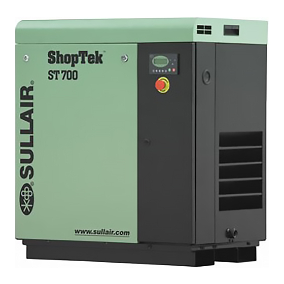
USER MANUAL
I
A
C
NDUSTRIAL
IR
OMPRESSOR
S
T
™
HOP
EK
ST400, ST500, ST700, ST1100, ST1500
4, 5, 7, 11 &15
: 5, 7.5, 10, 15 & 20
KW
HP
PART NUMBER:
02250180-090 R01
KEEP FOR
FUTURE
REFERENCE
WARRANTY NOTICE
SULLAIR CORPORATION
©
The information in this manual is current
as of its publication date, and applies to
Failure to follow the instructions
compressor serial number:
and procedures in this manual or,
Base Mount: C03-C20350
misuse of this equipment will
Tank Mount: 200811010000
VOID its warranty!
and all subsequent serial numbers.
Advertisement
Table of Contents


Need help?
Do you have a question about the ShopTek ST400 and is the answer not in the manual?
Questions and answers