Hioki PW3365 Measurement Manual
Clamp on power logger
Hide thumbs
Also See for PW3365:
- Measurement manual (2 pages) ,
- Selection manual (5 pages) ,
- Manual (12 pages)
Advertisement
Quick Links
PW3365-20
Thank you for purchasing the HIOKI PW3365-20
Clamp On Power Logger.
CLAMP ON POWER LOGGER
This guide introduces the PW3365-20's basic
measurement procedure with the Quick Set to
Measurement Guide
first time users.
Before using the instrument, be sure
Apr. 2018 Revised edition 1 Printed in Japan
to read the Instruction manual carefully.
PW3365A984-01 18-04H
Quick
Easy configuration with the
How to configure electric energy measurement for a
3-phase 4-wire 220 V line
Setting Items
Setting Example
Wiring
: 3P4W (3-phase 4-wire)
Clamp sensor
: Model 9661 (500 A rating)
Current range
: 50 A
Save to...
: SD memory card
Save interval
: 5 minutes
Save items
: Average only
Folder/Filename
: Automatic
Rec. start method
: Interval
Rec. stop method
: Manual
Color clips for clamp
Clock setting
: User-specified
sensors
Measurement frequency : 50 Hz
Preparations
1
Attach the color clips.
(CH1)
(CH2)
(CH3)
(N)
(CH1)
(CH2)
Red
Yellow
Blue
None
Red
Yellow
Model 9661
Model PW9020
1. Starting the Quick Set
First time powered
1
on only
Turn on the instrument.
on left side of instrument
(
)
Language setting
2
Press the
key.
Measurement
The Quick Set Start dialog will
frequency setting
be displayed.
(50 Hz)
1
3
Enter
Press the
key.
Set
You will need
Model PW9020 Safety Voltage Sensor x4
Model PW3365-20
Model 9661 Clamp on
Model Z1008 AC Adapter
Sensor (optional) x 3
Red (CH1)
Red (CH1)
Yellow (CH2)
Yellow (CH2)
Blue (CH3)
Blue (CH3)
SD memory card
Color clips for
(optional)
voltage sensors
2
3
Insert the SD memory
Connect the AC adapter.
card. (on right side of
on left side of instrument
(
instrument)
(CH3)
Be sure to provide a Hioki
optional SD Memory Card.
Blue
Operation is not guaranteed
with other SD memory cards.
2. Basic settings
1
Configure settings as
shown in screenshot
below.
2
3
2
Press the
Find Quality Products Online at:
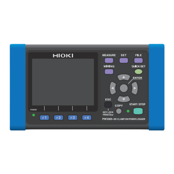
Names of Parts (excerpt)
POWER Switch
EN
3. Connect the sensors to the instrument.
Match the color of each sensor's color clip to the color
of the terminal.
Concept image
of measurement
3-phase 4-wire
220 V line
4. Connecting voltage sensors to the measurement target
)
3P4W
Proper application
Example: 3-phase 4-wire 220 V line
9661 (500 A)
Secondary side of breaker
Secondary
A
SD CARD
side
B
(Load side)
C
Set the current time.
N
OK
F2 [NEXT]
key.
Blue
Align the insulated wire with the
marks on the voltage sensor to
the wire.
For more information, see "3.6 Connecting
the Voltage Sensors to Target to be
Measured" in the instruction manual.
GlobalTestSupply
www.
.com
Voltage sensor input terminals
Current sensor input terminals
(Connect voltage sensors.)
(Connect clamp sensors.)
AC adapter
connection jack
Left
1
Connect the voltage sensors
to the voltage sensor input
terminals.
2
Connect the clamp sensors
to the current sensor input
terminals.
3
Be sure that the SD memory
card is inserted. (on right
side of instrument)
4
F2 [NEXT]
Press the
key.
1
Refer to the wiring diagram to check
the locations to which you have
connected the voltage sensors.
2
Connect the voltage sensors to the
secondary side of the breaker.
3
Check the readings.
In this example, the screen should indicate
approximately 220 V and 50 Hz if there is
no problem.
(Because the measurement target is a 220
V line, and the frequency being measured
is 50 Hz.)
4
Verify the results of checking the
wiring.
All results are
5
Press the
F2 [NEXT]
key.
Improper application
Failure to apply the sensor properly will prevent you from being to
make an accurate measurement.
Clamped with the
Clamped too far
tips of the clip
back in the clip
Red
Yellow
None
Tip
The power source side of the breaker is called the primary
side; whereas the load side, the secondary side.
For your safety, connect the voltage sensors and the clamp
sensors to the secondary side.
sales@GlobalTestSupply.com
SD memory
card slot
Upper
Right
Voltage sensor connector
Insert
Align
Voltage sensor input terminals
Clamp sensor connector (BNC)
1
Insert
Line up
Line up
2
Lock the
Current sensor
input terminals
connector.
1
Move the cursor to
item.
2
Enter
Press the
key.
3
Check the contents of the dialog box
and correct the wiring.
If there is a
.
result
Clamped with the
Clamping targets with
measurement target at an
different voltages at the
angle
same time
Primary side
Secondary side
A
B
C
Breaker
Source side
Load side
Advertisement

Related Manuals for Hioki PW3365


Summary of Contents for Hioki PW3365
- Page 1 Names of Parts (excerpt) PW3365-20 Thank you for purchasing the HIOKI PW3365-20 Voltage sensor input terminals Current sensor input terminals Clamp On Power Logger. POWER Switch CLAMP ON POWER LOGGER (Connect voltage sensors.) (Connect clamp sensors.) This guide introduces the PW3365-20's basic...
- Page 2 8. Recording settings 5. Connecting clamp sensors to the measurement target Rec. start method: INTERVAL Power source Example: With the save interval set to 5 min. Refer to the wiring diagram side Configure settings as shown in screenshot below. to check the locations to Start which you have connected Is this value shorter than the measurement interval?
Need help?
Do you have a question about the PW3365 and is the answer not in the manual?
Questions and answers