
Related Manuals for EXTREME SWITCHING ISW Series


Summary of Contents for EXTREME SWITCHING ISW Series
- Page 1 ISW Series Managed Industrial Ethernet Switch Hardware Installation & User Guide ISW 4-10/100P, 2-10/100T, 2-SFPISW 4GbP, 2GbT, 2- SFPISW 8-10/100P, 4-SFPISW 8GbP, 4-SFP 9034965-02 Rev AA November 2020...
- Page 2 Copyright © 2020 Extreme Networks, Inc. All rights reserved. Legal Notice Extreme Networks, Inc. reserves the right to make changes in specifications and other information contained in this document and its website without prior notice. The reader should in all cases consult representatives of Extreme Networks to determine whether any such changes have been made.
-
Page 3: Table Of Contents
Case 2: ACL for IP address...........................48 Case 3: ACL for L4 Port..........................48 Case 4: ACL for ToS............................48 Ring Version 2 Application Guide........................49 Ring Version 2 Features..........................49 Configuring Ringv2 (Console)........................50 ISW Series Managed Industrial Ethernet Switch Hardware Installation & User Guide... - Page 4 Federal Communications Commission (FCC) Notice................81 Industry Canada Notice CAN ICES-3 (A)/NMB-3(A)................81 Product Safety................................81 Electromagnetic Compatibility (EMC)......................82 Korea EMC Statement (KCC)..........................82 BSMI EMC Statement - Taiwan..........................82 Glossary..........................83 ISW Series Managed Industrial Ethernet Switch Hardware Installation & User Guide...
-
Page 5: Preface
Helpful tips and notices for using the product Note Useful information or instructions Important Important features or instructions Caution Risk of personal injury, system damage, or loss of data Warning Risk of severe personal injury ISW Series Managed Industrial Ethernet Switch Hardware Installation & User Guide... -
Page 6: Documentation And Training
Extreme Networks offers product training courses, both online and in person, as well as specialized certifications. For details, visit www.extremenetworks.com/education/. ISW Series Managed Industrial Ethernet Switch Hardware Installation & User Guide... -
Page 7: Getting Help
The Information Development team at Extreme Networks has made every effort to ensure the accuracy and completeness of this document. We are always striving to improve our documentation and help ISW Series Managed Industrial Ethernet Switch Hardware Installation & User Guide... - Page 8 Email us at documentation@extremenetworks.com. Provide the publication title, part number, and as much detail as possible, including the topic heading and page number if applicable, as well as your suggestions for improvement. ISW Series Managed Industrial Ethernet Switch Hardware Installation & User Guide...
-
Page 9: Industrial Series Switch Overview
Damage to the eye by accidental exposure to a beam emitted by a laser source. • Damage to the eye from viewing a connector attached to a broken fiber or an energized fiber. ISW Series Managed Industrial Ethernet Switch Hardware Installation & User Guide... -
Page 10: Faceplate And Panels
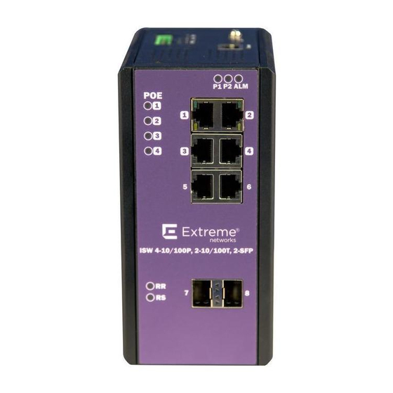
Faceplate and Panels Industrial Series Switch Overview Faceplate and Panels Figure 1: 4-Port PoE Series Faceplate ISW Series Managed Industrial Ethernet Switch Hardware Installation & User Guide... - Page 11 Front Panel System Status LED P1, P2 and Alarm Gigabit Ethernet Copper Ports RJ45 Gigabit Ethernet SFP ports SFP Slots POE LED POE port status RR/RS LED Device info/status ISW Series Managed Industrial Ethernet Switch Hardware Installation & User Guide...
-
Page 12: Led Status Indicators
Flashing Green detected Ethernet link down A 100 Mbps or a 1000 Mbps connection On Amber is detected Copper ports Speed No link or a 10 Mbps connection is detected ISW Series Managed Industrial Ethernet Switch Hardware Installation & User Guide... - Page 13 Homing/Chain/Balancing Chain failure (any node is link down), and then RS LED will be ON. All of the Ring ports are link up or Ring/ Coupling/Dual Homing/Chain/Balancing Chain is healthy. ISW Series Managed Industrial Ethernet Switch Hardware Installation & User Guide...
-
Page 14: Technical Specifications
Technical Specifications Industrial Series Switch Overview Technical Specifications Ethernet Operating mode Store and forward, L2 wire-speed/non-blocking switching engine MAC addresses Jumbo frames 9K Bytes Copper RJ45 Ports Speed 10/100/1000 Mbps ISW Series Managed Industrial Ethernet Switch Hardware Installation & User Guide... - Page 15 Reverse power protection Total PoE output power budget 120W (ISW 16801) / 240W (ISW 16803) PoE PSE port output power Scheduling; power control; PoE PD power consumption monitoring management ISW Series Managed Industrial Ethernet Switch Hardware Installation & User Guide...
- Page 16 DIN-Rail mounting, Wall mounting Dimension 77mm W x 154mm H x 128mm D (3 in. W x 6 in. H x 5 in. D) Weight Unpackaged:1.49kg (3.3 lb.); Packaged: 1.99kg (4.4 lb.) ISW Series Managed Industrial Ethernet Switch Hardware Installation & User Guide...
-
Page 17: System Statistics
MAC-based VLAN Entry IP subnet-based VLAN Entry Protocol-based VLAN Group Voice VLAN OUI IP Interface IP Route Security Access Management MVR VLAN MAC Learning table address IGMP Group 1000 ISW Series Managed Industrial Ethernet Switch Hardware Installation & User Guide... -
Page 18: Installing Industrial Switches
1. Screw the DIN-Rail bracket on with the bracket and screws in the accessory kit. 2. Hook the unit over the DIN rail. 3. Push the bottom of the unit towards the DIN Rail until it snaps into place. ISW Series Managed Industrial Ethernet Switch Hardware Installation & User Guide... -
Page 19: Mounting The Isw (Wall)
Installing Industrial Switches Mounting the ISW (Wall) Figure 4: DIN-Rail Mounting Mounting the ISW (Wall) Attach the wall-mounting plates with the screws provided in the accessory kit. ISW Series Managed Industrial Ethernet Switch Hardware Installation & User Guide... -
Page 20: Connecting The Ethernet Interface (Rj45 Ethernet)
To connect the ISW copper port to an Ethernet device, use UTP (Unshielded Twisted Pair) or STP (Shielded Twisted Pair) Ethernet cables. The pin assignment of RJ45 connector is shown in Figure 5 Table 5 ISW Series Managed Industrial Ethernet Switch Hardware Installation & User Guide... -
Page 21: Connecting The Ethernet Interface (Fiber)
LC connectors or SC connectors (with the use of an optional SC-to-LC adapter) to the fiber optics connector. Refer to LED Status Indicators on page 12 for the normal operational LED status. Figure 6: Fiber optics cable with LC duplex connector ISW Series Managed Industrial Ethernet Switch Hardware Installation & User Guide... - Page 22 Do not power up the laser product without connecting the laser to the optical fiber and putting the cover in position, as laser outputs will emit infrared laser light at this point. ISW Series Managed Industrial Ethernet Switch Hardware Installation & User Guide...
-
Page 23: Connecting The Power Terminal Block
The alarm relay out is “Normal Open,” and it will be closed when detected any predefined failure such as power failures or Ethernet link failures. The relay output with current carrying capacity of 0.5A @ 24 VDC. ISW Series Managed Industrial Ethernet Switch Hardware Installation & User Guide... -
Page 24: Console Connection
Figure 10, and then connect the DB9 connector to the PC COM port. Important Using a different cable than the one provided with the switch may cause bootup issues. ISW Series Managed Industrial Ethernet Switch Hardware Installation & User Guide... -
Page 25: System Reset
The Reset button is provided to reboot the system without the need to remove power. Under normal circumstances, you will not have to use it. However, on rare occasions, the ISW may not respond and you may need to push the Reset button. ISW Series Managed Industrial Ethernet Switch Hardware Installation & User Guide... -
Page 26: Connecting & Logging In To The Switch
Times New Roman Encoding Unicode (UTF-8) Text size Chrome Google Chrome with the following default settings is recommended: Web page font Times New Roman Encoding Unicode (UTF-8) Text size Medium ISW Series Managed Industrial Ethernet Switch Hardware Installation & User Guide... -
Page 27: Monitoring The Ethernet Interface
If you want to reset all configurations to the default: 4. Execute the command: reload defaults 5. Check interface VLAN and IP address, and confirm they all change to default settings. ISW Series Managed Industrial Ethernet Switch Hardware Installation & User Guide... -
Page 28: Resetting Configuration Defaults Via Web Ui
5. Change PC’s IP address belong to 192.0.2.X networks. 6. Change web’s IP be 192.0.2.1 (default IP) to login DUT’s Web UI. 7. Go to Maintenance > Configuration > Save startup config and then click Save Configuration. ISW Series Managed Industrial Ethernet Switch Hardware Installation & User Guide... -
Page 29: Isw Application Guides
The default configuration settings for ISW have all ports set as untagged members of VLAN 1 with all ports configured as PVID=1. In default configuration example shown in the following figure, all incoming packets are assigned to VLAN 1 by the default port VLAN identifier (PVID=1). ISW Series Managed Industrial Ethernet Switch Hardware Installation & User Guide... -
Page 30: Example 2: Port-Based Vlans
ISW through Port 2, which is configured as a tagged member of VLAN100. The untagged packet remains unchanged as it leaves the ISW through Port 7, which is configured as an untagged member of VLAN100. ISW Series Managed Industrial Ethernet Switch Hardware Installation & User Guide... - Page 31 The ISW should tag it with VID 100. The packet has access to Port1 and Port 2. For Port 1 and Port 2, the outgoing packet leaves as a tagged packet with VID 100. 9. Repeat step on page 31 using broadcast and multicast packets. ISW Series Managed Industrial Ethernet Switch Hardware Installation & User Guide...
-
Page 32: Example 3: Ieee 802.1Q Tagging
Port 7 is configured as an untagged member of VLAN 200. Hosts in the same VLAN communicate with each other as if they in a LAN. However, hosts in different VLANs cannot communicate with each other directly. ISW Series Managed Industrial Ethernet Switch Hardware Installation & User Guide... - Page 33 The ISW should tag it with VID 200. The packet only has access to Port1. The outgoing packet on Port 1 will leave as a tagged packet with VID 200. e. Repeat the above steps using broadcast and multicast packets. ISW Series Managed Industrial Ethernet Switch Hardware Installation & User Guide...
-
Page 34: Security Application Guide
Port, and Type of Service. Each has five actions: Deny, Permit, Queue Mapping, CoS (Class of Service) Marking, and Copy Frame. You can set the default ACL rule to Permit or Deny. ISW Series Managed Industrial Ethernet Switch Hardware Installation & User Guide... -
Page 35: Case 1: Acl For Mac Address
ACL. It means GE port can pass through all packets but not ACL entry of the profile binding. Case 1: (b) This case acts as no ACL function. It means all frames will pass through. ISW Series Managed Industrial Ethernet Switch Hardware Installation & User Guide... - Page 36 ACL Profile (profile name: DenySomeMac). 3. Create a new ACL Entry rule under this ACL profile. (Deny MAC: 11 and VLAN: 4) 4. Bind this ACL profile to a GE port (PORT4). ISW Series Managed Industrial Ethernet Switch Hardware Installation & User Guide...
- Page 37 1 ingress interface GigabitEthernet 1/4 policy 1 vid 4 frametype etype smac 00-00-00-00-00-11 action deny exit interface GigabitEthernet 1/3 switchport trunk allowed vlan 4,5 switchport trunk vlan tag native interface GigabitEthernet 1/4 switchport trunk allowed vlan 4,5 ISW Series Managed Industrial Ethernet Switch Hardware Installation & User Guide...
- Page 38 3. Create a new ACL Entry rule under this ACL profile (Deny SrcMAC: 13 and DesMAC: 11). 4. Bind this ACL profile to a GE port (PORT3). 5. Send frames between PORT3 and PORT4, and see test result. ISW Series Managed Industrial Ethernet Switch Hardware Installation & User Guide...
- Page 39 2. Create a new ACL Profile (profile name: CoSMarkingTest). 3. Create a new ACL Entry rule under this ACL profile (Filter SrcMAC: 11 and VLAN ID: 4 frame to CoS: ISW Series Managed Industrial Ethernet Switch Hardware Installation & User Guide...
- Page 40 1 next 2 ingress interface GigabitEthernet 1/4 policy 1 vid 4 frametype etype smac 00-00-00-00-00-11 action deny exit interface GigabitEthernet 1/3 switchport trunk allowed vlan 4,5 switchport trunk vlan tag native interface GigabitEthernet 1/4 ISW Series Managed Industrial Ethernet Switch Hardware Installation & User Guide...
- Page 41 3. Create a new ACL Entry rule under this ACL profile (SrcMAC: 13 and DesMAC: 11). 4. Set analyzer port to enable and mirror analyzer port. 5. Bind this ACL profile to a GE port (PORT3). ISW Series Managed Industrial Ethernet Switch Hardware Installation & User Guide...
- Page 42 2. Create a new ACL Profile (profile name: AllowSomeMac). 3. Create a new ACL Entry rule under this ACL profile (allow MAC: 11 and VLAN: 4). 4. Bind this ACL profile to a GE port (PORT4.) ISW Series Managed Industrial Ethernet Switch Hardware Installation & User Guide...
- Page 43 4 ingress interface GigabitEthernet 1/4 policy 3 tag tagged vid 4 frametype etype smac 00-00-00-00-00-11 exit interface GigabitEthernet 1/3 switchport trunk allowed vlan 4,5 switchport trunk vlan tag native interface GigabitEthernet 1/4 switchport trunk allowed vlan 4,5 ISW Series Managed Industrial Ethernet Switch Hardware Installation & User Guide...
- Page 44 2. Create a new ACL Profile (profile name: AllowSomeMac). 3. Create a new ACL Entry rule under this ACL profile (allow SrcMAC: 13 and DesMAC: 11). 4. Bind this ACL profile to a GE port (PORT3). ISW Series Managed Industrial Ethernet Switch Hardware Installation & User Guide...
- Page 45 Configuring One-directional MAC Address with Copy Frame Action (don’t care VLAN, Ether Type) – Web UI 1. Navigate to Configuration > Security > Network > ACL > Access Control List. 2. Create a new ACL Profile (profile name: CopyFrameTest). ISW Series Managed Industrial Ethernet Switch Hardware Installation & User Guide...
- Page 46 3. Create a new ACL Entry rule under this ACL profile (SrcMAC: 13 and DesMAC: 11). 4. Bind this ACL profile to a GE port (PORT3). 5. Save the entry. ISW Series Managed Industrial Ethernet Switch Hardware Installation & User Guide...
- Page 47 Configuring One-directional MAC Address with Copy Frame Action (don’t care VLAN, Ether Type) – CLI Commands access-list ace 5 next 6 ingress interface GigabitEthernet 1/3 policy 5 frametype etype smac 00-00-00-00-00-13 dmac 00-00-00-00-00-11 Exit ISW Series Managed Industrial Ethernet Switch Hardware Installation & User Guide...
-
Page 48: Case 2: Acl For Ip Address
The detail testing, please refer to case 1 MAC ACL above. Valid Values: Precedence: 0-7, ToS: 0-15, DSCP: 0-63 Value 7 is reserved and set to 0. ISW Series Managed Industrial Ethernet Switch Hardware Installation & User Guide... -
Page 49: Ring Version 2 Application Guide
# When role is coupling/primary, only it need configure one ring port named primary port. # When role is coupling/backup, only it need configure one ring port named backup port. This backup port is redundant port. In normal state, it is blocked. ISW Series Managed Industrial Ethernet Switch Hardware Installation & User Guide... -
Page 50: Configuring Ringv2 (Console)
PORT-2. Then choose one of ring connection devices be “Master” that can accept the “Node 2 port” and be the blocking port. node1 interface GigabitEthernet 1/1 node2 interface GigabitEthernet 1/2 role ring-master ISW Series Managed Industrial Ethernet Switch Hardware Installation & User Guide... -
Page 51: Configuring Ringv2 (Web Ui)
1. Disable RSTP on all ring ports by navigating to Configuration > Spanning Tree > CIST ports. 2. Clear STP Enabled on the desired ring ports. 3. Click Save. ISW Series Managed Industrial Ethernet Switch Hardware Installation & User Guide... - Page 52 Configuring Ring Master 1. Navigate to Configuration > RingV2. 2. Enable Index1, and select role as Ring(Master). 3. Select one port as a Forward Port, and another as Block Port. ISW Series Managed Industrial Ethernet Switch Hardware Installation & User Guide...
- Page 53 2. Enable Index1, and select role as Ring(Slave). 3. Select two ports as Forward Ports. 4. Enable Index2, and select role as Coupling(Primary). 5. Select one port as a Primary Port. ISW Series Managed Industrial Ethernet Switch Hardware Installation & User Guide...
- Page 54 3. Select two ports as Forward Ports. 4. Enable Index2, and select role as Coupling(Backup). 5. Select one port as a Backup Port. Configuring Dual-Homing 1. Navigate to Configuration > RingV2. ISW Series Managed Industrial Ethernet Switch Hardware Installation & User Guide...
-
Page 55: Chain Configuration
1. Navigate to Configuration > RingV2. 2. Disable Index1 and Index2, and then enable Index3. 3. Select role as Chain(Member). 4. Select two member ports for this chain member switch. ISW Series Managed Industrial Ethernet Switch Hardware Installation & User Guide... - Page 56 1. Navigate to Configuration > RingV2. 2. Disable Index1 and Index2, and then enable Index3. 3. Select role as Chain(Head). 4. Select a member port and a head port for this chain head switch. ISW Series Managed Industrial Ethernet Switch Hardware Installation & User Guide...
-
Page 57: Balance Chain Configuration
2. Disable Index1 and Index2, and then enable Index3. 3. Select role as Balancing Chain(Central Block). 4. Select a member port and a block port for this central block switch. ISW Series Managed Industrial Ethernet Switch Hardware Installation & User Guide... - Page 58 2. Disable Index1 and Index2, and then enable Index3. 3. Select role as Balancing Chain(Terminal-1 or -2). 4. Select a member port and a terminal port for this balancing chain terminal switch. ISW Series Managed Industrial Ethernet Switch Hardware Installation & User Guide...
-
Page 59: Qos Application Guide
We expect PORT-2 only can receive 100Mbps of Stream1, and Stream0 will be discarded. This case will help you to understand how SPQ works on the ISW. Figure 12: Gigabit port VLAN Priority & Queue Mapping ISW Series Managed Industrial Ethernet Switch Hardware Installation & User Guide... - Page 60 Vlan prio : 7 • Send rate : 100Mbps • Packet length: 1518bytes Web Management 1. Navigate to Configuration > Ports. 2. Set port 2 link speed to 100Mbps full duplex. ISW Series Managed Industrial Ethernet Switch Hardware Installation & User Guide...
- Page 61 We expect PORT-2 only can receive 20Mbps of Stream1, and 80Mbps of Stream0. This case will help you to understand how SPQ works on the ISW. Figure 13: VDSL port VLAN Priority & Queue Mapping ISW Series Managed Industrial Ethernet Switch Hardware Installation & User Guide...
- Page 62 Vlan prio : 0 • Send rate : 10Mbps • Packet length: 1518bytes Web Management 1. Navigate to Configuration > QoS > Port Shaping and create a QoS profile on Port 2. ISW Series Managed Industrial Ethernet Switch Hardware Installation & User Guide...
- Page 63 ISW Application Guides Application Examples 2. Select schedule mode Strict Priority and set shaping rate for queue 0 and queue 7 as below. ISW Series Managed Industrial Ethernet Switch Hardware Installation & User Guide...
- Page 64 GigabitEthernet 1/2 switchport trunk native vlan 100 switchport trunk allowed vlan 1,100 switchport trunk vlan tag native switchport mode trunk qos queue-shaper queue 0 80000 qos queue-shaper queue 7 20000 ISW Series Managed Industrial Ethernet Switch Hardware Installation & User Guide...
-
Page 65: Igmp Application Guide
Example 1 If every client should get multicast stream, navigate to Configuration > IPMC > Basic Configuration to select the Snooping Enabled check box. ISW Series Managed Industrial Ethernet Switch Hardware Installation & User Guide... - Page 66 Example 1 ISW Application Guides ISW Series Managed Industrial Ethernet Switch Hardware Installation & User Guide...
-
Page 67: Example 2
4. If Multicast stream is from L3 switch, then the uplink port must be “Router Port.” Note If an aggregation member port is selected as a router port, the whole aggregation will act as a router port. ISW Series Managed Industrial Ethernet Switch Hardware Installation & User Guide... - Page 68 Example 2 ISW Application Guides 5. Go to Configuration > IPMC > VLAN Configuration. 6. Select the Snooping Enabled check box. 7. Set VLAN ID of port14. ISW Series Managed Industrial Ethernet Switch Hardware Installation & User Guide...
-
Page 69: Example 3
6. If there is no querier on the L3 switch, you have to select Querier Election, and set the Querier Address. The IP address is in the same network as uplink interface. ISW Series Managed Industrial Ethernet Switch Hardware Installation & User Guide... -
Page 70: 802.1X Authentication Application Guide
The secret in the ISW should be the same as this one. 3. Edit user name and password for supplicant to authenticate with server with the following settings: test123..Cleartext-Password := “test123” aaaa..Cleartext-Password := “aaaa” ISW Series Managed Industrial Ethernet Switch Hardware Installation & User Guide... - Page 71 Below is an example 802.1x Authentication via ISW to be authenticated by RADIUS server. In this basic example, we take port 1 as a testing port, which enables 802.1x in ISW. ISW Series Managed Industrial Ethernet Switch Hardware Installation & User Guide...
- Page 72 1. Navigate to Configuration > Security > > Network > NAS. 2. Select Enabled mode to enable authentication. 3. Set port1 and port2 as Port-based 802.1x. 4. Navigate to Configuration > Security > AAA > RADIUS. ISW Series Managed Industrial Ethernet Switch Hardware Installation & User Guide...
-
Page 73: 802.1X Timer Parameters
Quiet Period is not running. Supplicant Timeout ISW will wait SupplicantTmeout to receive response from Supplicant. Server Timeout ISW will wait ServerTimeout to receive response from RADIUS server. ISW Series Managed Industrial Ethernet Switch Hardware Installation & User Guide... -
Page 74: Power Over Ethernet (Poe) Application Guide
ISW Application Guides Power over Ethernet (PoE) Application Guide The ISW series switches support PoE function for connected powered device. The operation mode contains 802.3af (15.4W), 802.3at (30W). Each port has five classes for selection (class 0–4). Total power budget of the system is up to 240 watts. -
Page 75: Power Management Mode
The ports are shut down according to the ports priority. If two ports have the same priority the port with the highest port number is shut down. Port Priority: Critical > High > Low. ISW Series Managed Industrial Ethernet Switch Hardware Installation & User Guide... -
Page 76: Other Poe Parameters
The PoE Mode represents the PoE operating mode for the port. • Disable: PoE disabled for the port. • Enable: Enables PoE for the port. • Schedule: Enables PoE for the port by scheduling. Operation Mode ISW Series Managed Industrial Ethernet Switch Hardware Installation & User Guide... -
Page 77: Poe Power Scheduling & Reset
Directly changes checkmarks to indicate which day are members of the time interval. Check or uncheck as needed to modify the scheduling table. ISW Series Managed Industrial Ethernet Switch Hardware Installation & User Guide... - Page 78 3. PD Power Consumption • Port 1: 1.3 watt (PoE Splitter) • Port 2: 1.3 watt (PoE VoIP Phone) • Port 3: 3.8 watt (PoE WiFi AP) 4. Web Configuration ISW Series Managed Industrial Ethernet Switch Hardware Installation & User Guide...
- Page 79 Total: 137.8 W 3. PD Power Consumption • Port 1: 1.3 watt (PoE Splitter) Port 2: 1.3 watt (PoE VoIP Phone) • Port 3: 3.8 watt (PoE WiFi AP) ISW Series Managed Industrial Ethernet Switch Hardware Installation & User Guide...
- Page 80 PoE port status can be monitored by web: Monitor > PoE. Because power has reserved for each port in advance, each powered device can use power budget of its corresponding port without exceeding its maximum power. ISW Series Managed Industrial Ethernet Switch Hardware Installation & User Guide...
-
Page 81: Regulatory And Compliance Information
This product complies with the following international safety standards: • UL 60950-1 2nd edition, A2:2014 • CAN/CSA-C22.2 No.60950-1-07 2nd Ed. 2014-10 • IEC 60950-1:2005 2nd+A1:2009+A2:2013 • EN 60950-1:2006+A11+A1+A12+A2 • 2014/35/EU (2006/95/EC will invalid by 20 April 2016) ISW Series Managed Industrial Ethernet Switch Hardware Installation & User Guide... -
Page 82: Electromagnetic Compatibility (Emc)
BSMI EMC Statement - Taiwan This is a Class A product. In a domestic environemnt this product may cause radio interference in which case the user may be required to take adequate measurers. ISW Series Managed Industrial Ethernet Switch Hardware Installation & User Guide... -
Page 83: Glossary
The protocol supports static or dynamic IP addresses and can dynamically reconfigure networks in which there are more computers than there are available IP addresses. DoS attack ISW Series Managed Industrial Ethernet Switch Hardware Installation & User Guide... - Page 84 Glossary Denial of Service attacks occur when a critical network or computing resource is overwhelmed so that legitimate requests for service cannot succeed. In its simplest form, a DoS attack is indistinguishable from normal heavy traffic. ExtremeXOS software has configurable parameters that allow you to defeat DoS attacks.
- Page 85 Glossary Internet Control Message Protocol is the part of the TCP/IP protocol that allows generation of error messages, test packets, and operating messages. For example, the ping command allows you to send ICMP echo messages to a remote IP device to test for connectivity. ICMP also supports traceroute, which identifies intermediate hops between a given source and destination.
- Page 86 Glossary time voice. Networks must provide secure, predictable, measurable, and sometimes guaranteed services. Achieving the required QoS becomes the secret to a successful end-to-end business solution. RADIUS RADIUS is a client/server protocol and software that enables remote access servers to communicate with a central server to authenticate dial-in users and authorize their access to the requested system or service.
Need help?
Do you have a question about the ISW Series and is the answer not in the manual?
Questions and answers