
Related Manuals for EXTREME SWITCHING Virtual Services Platform 8000 Series


Summary of Contents for EXTREME SWITCHING Virtual Services Platform 8000 Series
- Page 1 Installing the Virtual Services Platform 8000 Series Release 6.1 NN47227-300 Issue 11.02 December 2017...
- Page 2 © REPRESENT THAT YOU HAVE THE AUTHORITY TO BIND SUCH 2017, Extreme Networks, Inc. ENTITY TO THESE TERMS OF USE. IF YOU DO NOT HAVE SUCH All Rights Reserved. AUTHORITY, OR IF YOU DO NOT WISH TO ACCEPT THESE Notice TERMS OF USE, YOU MUST NOT ACCESS OR USE THE HOSTED SERVICE OR AUTHORIZE ANYONE TO ACCESS OR While reasonable efforts have been made to ensure that the...
- Page 3 including any code and software unless expressly authorized by THE PERSONAL USE OF A CONSUMER OR OTHER USES IN Extreme Networks. Unauthorized reproduction, transmission, WHICH IT DOES NOT RECEIVE REMUNERATION TO: (I) ENCODE dissemination, storage, and or use without the express written VIDEO IN COMPLIANCE WITH THE AVC STANDARD (“AVC consent of Extreme Networks can be a criminal, as well as a civil VIDEO”) AND/OR (II) DECODE AVC VIDEO THAT WAS ENCODED...
- Page 4 For additional information on Extreme Networks trademarks, please see: http://www.extremenetworks.com/company/legal/...
-
Page 5: Table Of Contents
Subscribing to e-notifications Chapter 2: New in this document..................12 Chapter 3: Hardware models for VSP 8000 Series.............. 13 Chapter 4: Preinstallation checklist..................19 Chapter 5: Installing the Virtual Services Platform 8000 Series......... 21 ....................... 21 Installation checklist ....................... 22 Installation fundamentals ...................... - Page 6 Contents ..........86 SFP, SFP+,QSFP+, and QSFP28 port LED state indicators ..................87 RJ45 port LED state indicators ..................88 Channelized LED state indicators ......89 Enterprise Device Manager (EDM) representation of physical LED status ......................89 40GBASE-QSFP+ ports Chapter 6: Translations of safety messages................ 90 December 2017 Installing the VSP 8000 Series...
-
Page 7: Chapter 1: Preface
Chapter 1: Preface Purpose This guide provides information and instructions to install the Extreme Networks Virtual Services Platform 8000 Series (VSP 8000 Series) switches. The VSP 8000 Series includes the VSP 8200 and the VSP 8400. Training Ongoing product training is available. For more information or to register, you can access the Web site at www.extremenetworks.com/education/. -
Page 8: Extreme Networks Documentation
Preface If you require assistance, contact Extreme Networks using one of the following methods: • GTAC (Global Technical Assistance Center) for Immediate Support - Phone: 1-800-998-2408 (toll-free in U.S. and Canada) or +1 408-579-2826. For the support phone number in your country, visit: www.extremenetworks.com/support/contact - Email: support@extremenetworks.com. -
Page 9: Subscribing To E-Notifications
Subscribing to e-notifications Current Product Documentation www.extremenetworks.com/documentation/ Archived Documentation (for previous www.extremenetworks.com/support/documentation- archives/ versions and legacy products) Release Notes www.extremenetworks.com/support/release-notes Open Source Declarations Some software files have been licensed under certain open source licenses. More information is available at: www.extremenetworks.com/support/policies/software-licensing. Subscribing to e-notifications Subscribe to e-notifications to receive an email notification when documents are added to or changed on the Avaya Support website. - Page 10 Preface 6. Click OK. 7. In the PRODUCT NOTIFICATIONS area, click Add More Products. 8. Scroll through the list, and then select the product name. 9. Select a release version. 10. Select the check box next to the required documentation types. December 2017 Installing the VSP 8000 Series...
- Page 11 Subscribing to e-notifications 11. Click Submit. December 2017 Installing the VSP 8000 Series...
-
Page 12: Chapter 2: New In This Document
Chapter 2: New in this document There are no feature changes in this document. December 2017 Installing the VSP 8000 Series... -
Page 13: Chapter 3: Hardware Models For Vsp 8000 Series
Chapter 3: Hardware models for VSP 8000 Series This section lists the VSP 8000 Series hardware. VSP 8200 hardware Table 1: VSP 8284XSQ Hardware VSP 8284XSQ Description Part number VSP 8284XSQ-AC • 80 ports of 10GBASE-SFP+ EC8200x01-E6 This model number ships with •... - Page 14 Hardware models for VSP 8000 Series VSP 8284XSQ Description Part number This model number is also TAA compliant and ships with an AC power supply. However, it includes a North American power cord. Redundant power supplies 800 watt AC redundant power •...
- Page 15 VSP 8400 hardware The following tables describe the VSP 8400 hardware. Table 2: VSP 8404 Hardware VSP 8404 Description Part number VSP 8404 AC • one 10/100/1000BASE-T Out-Of-Band EC8400x01-E6 Management Port This model number ships with Note: one field-replaceable 800 watt •...
- Page 16 Hardware models for VSP 8000 Series VSP 8404 Description Part number VSP 8404–DC Includes all of the above components. EC8400001-E6 This model number ships with one field-replaceable 800 watt DC power supply. VSP 8404C–DC Includes all of the above components. EC8400002-E6 This model number ships with one field-replaceable 800 watt...
- Page 17 VSP 8404 Description Part number Note: The universal slide rack mount kit is optional and must be ordered separately. VSP 7200, VSP 8200 and VSP 8400 ship with rack mount brackets. When using rack mount brackets on VSP 8200 and VSP 8400, Extreme Networks recommends the use of a shelf to provide additional support.
- Page 18 Hardware models for VSP 8000 Series Model Name Description Part Number Note: This ESM operates only with the VSP 8404C model. 8402CQ (TAA-compliant) 2 port 100G QSFP28 Ethernet Switch Module EC8404009-E6GS Note: This ESM operates only with the VSP 8404C model.
-
Page 19: Chapter 4: Preinstallation Checklist
Chapter 4: Preinstallation checklist Before you install the VSP 8000 Series, make sure that you complete the tasks in the preinstallation checklist. Task Description Review the technical specification for For the physical, electrical, and environmental the switch. Make sure that the area specifications, see Technical specifications where you install the switch and where... - Page 20 Preinstallation checklist Task Description permanent and must not exceed 1 Ohm of resistance from the rack to the grounding electrode. December 2017 Installing the VSP 8000 Series...
-
Page 21: Chapter 5: Installing The Virtual Services Platform 8000 Series
Chapter 5: Installing the Virtual Services Platform 8000 Series This section provides the information and procedures to install the VSP 8000 Series. Installation checklist Use this checklist to install the VSP 8000 Series. Task Description Mount the VSP 8000 Series switch Installing the VSP 8000 Series in an in the equipment rack. -
Page 22: Installation Fundamentals
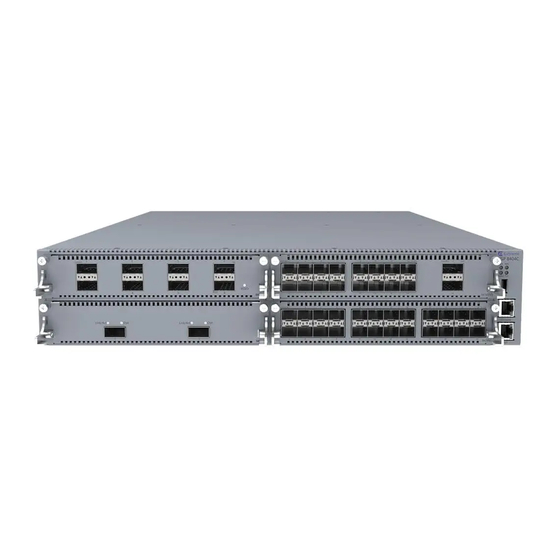
Installing the Virtual Services Platform 8000 Series Installation fundamentals VSP 8200 The VSP 8200 consists of: • eighty 10GBASE-SFP/SFP+ ports • four 40GBASE-QSFP+ ports • one 10/100/1000BASE-T Out-Of-Band Management Port • one RJ-45 Console Port • one USB 2.0 port •... - Page 23 Installation fundamentals 7. Management port — The LEDs are on the bottom of the port. For more information, see Management port LEDs on page 85. 8. LEDs for system power (PWR), switch status (Status), redundant power supply (RPS), and fan modules (Fan).
-
Page 24: Ethernet Switch Module
Installing the Virtual Services Platform 8000 Series Note: • The front view is common for both VSP 8404 and VSP 8404C models. • When looking at the front of the switch, slot numbering begins at the top row and increases from left to right. Slot 1 is the top-left slot; slot 2 is the top-right slot. Slot 3 is the bottom-left slot;... - Page 25 Ethernet Switch Module Power and 93.32W (max) = 318.41 BTU/hr thermal Figure 4: 8424XS 8424XT • 8424XT — EC8404002-E6 – provides 24 100MB/1G/10G Copper ports. • 8424XT (GSA version) — EC8404002-E6GS – 24 port 100MB/1G/10G Copper ports. Dimension 4.4cm – 1RU (H), 20.32cm (W), 29.21cm (D) Weight 4.05 lbs = 1.84 kg Power and...
- Page 26 Installing the Virtual Services Platform 8000 Series Note: As shown in the above figure, ports 7 and 8 are reserved for future use. 8418XSQ • 8418XSQ — EC8404005-E6 – 16 1/10G SFP+ and 2 40G QSFP+ ports. • 8418XSQ (GSA version) — EC8404005-E6GS – 16 1/10G SFP+ and 2 40G QSFP+ ports.
- Page 27 Ethernet Switch Module Figure 9: 8424GS 8424GT • 8424GT — EC8404008-E6 – 24 10/100/1000M Copper ports. • 8424GT (GSA version) — EC8404008-E6GS – 24-port 10/100/1000M Copper ports. Dimension 4.4cm – 1RU (H), 20.32cm (W), 29.21cm (D) Weight 2.75 lbs = 1.25 kg Power and 12.62W (max) = 47.90 BTU/hr thermal...
-
Page 28: Installing An Ethernet Switch Module
Installing the Virtual Services Platform 8000 Series Installing an Ethernet Switch Module Install an ESM to replace an existing module or to add new capability. The switch has four bays and you can choose any one of them to install a module. The switch detects where the modules are installed so the order is not important. - Page 29 Ethernet Switch Module 2. Slide the module into the bay. 3. Apply gentle pressure anywhere on the faceplate to fully insert the module, and then screw the module in to ensure a good connection and to secure it to the chassis. December 2017 Installing the VSP 8000 Series...
-
Page 30: Hot Swap Of Vsp 8400 Ethernet Switch Module
Installing the Virtual Services Platform 8000 Series Note: The levers are designed to stay in the position shown when the module is inserted into the chassis. The levers are pulled upwards to extract the module. If you have to remove a module, loosen the two screws that secure the module to the chassis and rotate the extract levers up to eject the module from the chassis. - Page 31 Ethernet Switch Module Table 4: Methods of hot swapping in VSP 8400 Hardware Description Power supply You can hot swap power supplies while the switch is operational. One power supply is required for continuous switch operation. 8402CQ ESM Hot insertion or removal of the 8402CQ is not supported. 8402CQ can only be hot swapped with another 8402CQ using Performing a Note:...
-
Page 32: 40G Channelization
Installing the Virtual Services Platform 8000 Series Important: Controlled hot swap is mandatory for 8402CQ ESM. Procedure 1. Enter Global Configuration mode: enable configure terminal 2. Shut down the slot: no sys power slot {slot[-slot][,...]} slot shutdown {slot[-slot][,...]} Note: slot reset command is not equivalent to controlled hot swap, and it is not sufficient for 8402CQ module reinsertion. -
Page 33: Electrostatic Discharge
Electrostatic discharge Electrostatic discharge This section provides information and procedures to prevent electrostatic discharge during installation. Preventing electrostatic discharge damage Electrostatic discharge (ESD) is a discharge of stored static electricity that can damage equipment and impair electrical circuitry. Electrostatic voltages can result from friction including, pulling cabling through conduits, walking across carpeted areas, and building static charge in clothing. -
Page 34: Technical Specifications
Installing the Virtual Services Platform 8000 Series Figure 12: Job aid To install the ESD discharge cable, perform this procedure. 1. Connect the ground lug on the ESD discharge cable to a safe and suitable earth ground. 2. Connect all RJ-45 cable connectors to the female RJ-45 connector of the ESD discharge cable for at least 5 seconds, and then connect each RJ-45 cable connector to the switch. - Page 35 Technical specifications Specifications 8200 8400 power supplies or ESMs) (EC8400x01-E6) Weight of spare AC power 1.9 lb (0.862 kg) (EC8005x01-E6) 1.9 lb (0.862 kg) (EC8005x01-E6) supply unit Weight of spare DC power 1.76 lb (0.8 kg) (EC8005001-E6) 1.76 lb (0.8 kg) (EC8005001-E6) supply unit Table 6: Electrical specifications Specifications...
-
Page 36: Package Contents
Installing the Virtual Services Platform 8000 Series Acoustic Noise Less than or equal to 35 db at 21° C and less than or equal to 43 db at 50° C. The temperature is allowed to have ±3.5° C deviation around the threshold of 35C, (measurement methods based on ISO 7779). -
Page 37: Installing The Vsp 8000 Series In An Equipment Rack
Installing the VSP 8000 Series in an equipment rack • The VSP 8404 DC model (EC8400001-E6) ships with a DC power supply wiring assembly for the DC power supply. • The VSP 8404 AC PS No PC GSA model (EC8400A01–E6GS) does not include a power cord. -
Page 38: Using The Optional Slide Rack Mount Kit
Installing the Virtual Services Platform 8000 Series Note: It is highly recommended to mount the chassis on a tray designed for the specific rack and use the Extreme Networks supplied rack mount brackets to hold the chassis in place. The chassis is heavy and could cause damage to a rack if only the brackets are used, especially in a vibration prone area. - Page 39 Installing the VSP 8000 Series in an equipment rack The shipping carton contains the following components: • Two 300mm-600mm slides (default configuration) • Two extension brackets for the 600mm-900mm configuration • Two long rear brackets for the 600mm-900mm configuration • Bag of screws Figure 13: Shipping components Rails The following figure shows a slide rail in the default configuration for a 300mm-600mm equipment...
- Page 40 Installing the Virtual Services Platform 8000 Series Figure 14: Rails Brackets There are three different brackets: • Short rear bracket—The slide rail kit comes with this bracket installed for the 300mm-600mm default configuration. Figure 15: Short rear bracket December 2017...
- Page 41 Installing the VSP 8000 Series in an equipment rack • Extension bracket—This bracket connects to the rack rail to lengthen it for a 600mm-900mm configuration. • Long rear bracket—This bracket replaces the short rear bracket to modify the slide rail for a 600mm-900mm configuration.
- Page 42 Installing the Virtual Services Platform 8000 Series Figure 17: Thumbscrew lock and release latches • Thumbscrew lock—This feature is on the front end of the chassis rails, and is used to lock the switch in the home position of the equipment rack.
- Page 43 Installing the VSP 8000 Series in an equipment rack • White release latch—This latch is the white, plastic tab on the chassis rails. - When you first install the slide rails, use these latches to disconnect the chassis rail from the rack rail so you can install the chassis rail on the switch.
- Page 44 Installing the Virtual Services Platform 8000 Series Figure 21: Blue locking mechanism - When you first install the slide rails and you fully extended the rail, you can lift the locking mechanism to release the rail so it can slide back into the main part of the unit.
- Page 45 Installing the VSP 8000 Series in an equipment rack • Pin block—The pin block supports equipment racks with different shaped holes. - For racks with square holes, the pin block fits right into the holes in the rack. - For racks with large round holes, the pin block retracts halfway when you insert the rail into the rack.
- Page 46 Installing the Virtual Services Platform 8000 Series Installing slides in a 300mm-600mm equipment rack Use the following procedure to install your switch in an equipment rack with a depth between 300mm and 600mm. Before you begin Important: The Slide Rack Mount Kit is fairly complex due to its versatile design. To make your...
- Page 47 Installing the VSP 8000 Series in an equipment rack b. Pull the inner chassis rail and slide it out as far as you can. December 2017 Installing the VSP 8000 Series...
- Page 48 Installing the Virtual Services Platform 8000 Series c. Slide the white release latch in the direction of the arrow stamped on the lock and pull the chassis rail out of the rack rail. 4. Lift the blue locking mechanism on the rack rail to slide the outer section back into the main section.
- Page 49 Installing the VSP 8000 Series in an equipment rack 5. Use the following steps to attach the chassis rail to the chassis: a. Orient the chassis rail with the thumbscrew lock towards the front and position the rail over the standoffs on the chassis. b.
- Page 50 Installing the Virtual Services Platform 8000 Series c. Make sure the safety tab locks into place. 6. Use the following steps to secure the rack rails to the frame: a. Orient the rack rail so that the end with the black retaining latch is facing front.
- Page 51 Installing the VSP 8000 Series in an equipment rack c. Push the end of the retaining latch out so it opens up. d. Insert the bracket pins into the desired holes in the frame. The pin block accommodates three different rack types. In the default position, the pin block fits into racks with square holes.
- Page 52 Installing the Virtual Services Platform 8000 Series e. Close the retaining latch so that it wraps around the frame and locks into place. f. Repeat the above steps on the rear bracket. g. Repeat these steps for the rack rail on the other side of the frame.
- Page 53 Installing the VSP 8000 Series in an equipment rack b. Pull the blue latches on the chassis rails towards the front and slide the switch into the frame. Note: After you install the switch in a rack, slide it out until the lock (shown above) engages. To slide the switch back into the rack, push the blue release latches on the chassis rails towards the back and slide the switch into the frame.
- Page 54 Installing the Virtual Services Platform 8000 Series Installing slides in a 600mm-900mm equipment rack Use the following procedure to install your switch in an equipment rack with a depth between 600mm and 900mm. Before you begin Important: The Slide Rack Mount Kit is fairly complex due to its versatile design. To make your...
- Page 55 Installing the VSP 8000 Series in an equipment rack b. Pull the inner chassis rail and slide it out as far as you can. December 2017 Installing the VSP 8000 Series...
- Page 56 Installing the Virtual Services Platform 8000 Series c. Slide the white release latch in the direction of the arrow stamped on the lock and pull the chassis rail out of the rack rail. 4. Lift the blue locking mechanism on the rack rail to slide the outer section back into the main section.
- Page 57 Installing the VSP 8000 Series in an equipment rack 5. Use the following steps to attach the chassis rail to the chassis: a. Orient the chassis rail with the thumbscrew lock towards the front and position the rail over the standoffs on the chassis. b.
- Page 58 Installing the Virtual Services Platform 8000 Series c. Make sure the safety tab locks into place. 6. Remove the two screws and nuts securing the short rear bracket to the rack rail. This bracket is for 300mm-600mm equipment racks only and is not used in this installation.
- Page 59 Installing the VSP 8000 Series in an equipment rack 7. Identify the extension bracket and the long rear bracket. Use these brackets to extend the rack rail for 600mm-900mm racks. December 2017 Installing the VSP 8000 Series...
- Page 60 Installing the Virtual Services Platform 8000 Series 8. Use the countersink screws with the following steps to attach the extension bracket to the rack rail: a. Push the blue release lock up and slide the middle rail out as far as possible.
- Page 61 Installing the VSP 8000 Series in an equipment rack Note: Using the bag with ten M4 screws, attach the extension bracket to the rack rail by inserting the screws from the rack rail side and then into the extension bracket. The following figure shows the extension bracket attached to the rack rail.
- Page 62 Installing the Virtual Services Platform 8000 Series d. Insert the long rear bracket into the extension bracket assembly. e. Install the first two screws on the end of the long rear bracket. f. Lift the blue locking mechanism and slowly slide the rail back into the main assembly.
- Page 63 Installing the VSP 8000 Series in an equipment rack screws one at a time. 9. Use the following steps to secure the rack rails to the frame: a. Orient the rack rail so that the end with the black retaining latch is in the front of the rack.
- Page 64 Installing the Virtual Services Platform 8000 Series c. Push the end of the retaining latch out so it opens up. d. Insert the bracket pins into the desired holes in the frame. The pin block accommodates three different rack types. In the default position, the pin block fits into racks with square holes.
- Page 65 Installing the VSP 8000 Series in an equipment rack e. Close the retaining latch so that it wraps around the frame and locks into place. f. Repeat the above steps on the rear bracket. 10. Repeat these steps for the rack rail on the other side of the frame. 11.
- Page 66 Installing the Virtual Services Platform 8000 Series b. Pull the blue release latches on the chassis rails towards the front and slide the switch into the frame. Note: After you install the switch in a rack, slide it out until the lock (shown above) engages.
- Page 67 Installing the VSP 8000 Series in an equipment rack Important notice about rack safety One prerequisite to installing the switch in an equipment rack is to bolt the equipment rack to the floor. This section emphasizes the safety issue if you do not bolt the rack to the floor. Warning: If you pull the chassis all the way out on the slide rails, there is a danger of the rack tipping over if the rack is not bolted to the floor.
- Page 68 Installing the Virtual Services Platform 8000 Series Removing the switch from an equipment rack Follow these steps if you have to remove the switch from an equipment rack. Important: This procedure requires two people. Procedure 1. Disconnect the power cord from the switch.
- Page 69 Installing the VSP 8000 Series in an equipment rack 3. While the person standing in back of the chassis slides both of the white release locks (one on each side of the chassis) towards the front, the person standing in front of the chassis pulls the chassis out of the rack.
-
Page 70: Using The Supplied Brackets
Installing the Virtual Services Platform 8000 Series Using the supplied brackets This procedure describes how to install the switch using the supplied brackets on a two-post or four-post equipment rack. The brackets secure the chassis and prevent it from sliding around during vibration or when inserting or extracting transceivers. -
Page 71: Cable Requirements For The Vsp 8000 Series
Cable requirements for the VSP 8000 Series 4. Insert and tighten the rack-mount screws. 5. Verify that the switch is securely fastened to the rack. 6. Connect power and network connections to the switch. Cable requirements for the VSP 8000 Series The following table describes the cables required for a VSP 8000 Series switch. -
Page 72: Installation And Removal Of Transceivers
Installing the Virtual Services Platform 8000 Series Required Cable Description connector on one end and an RJ-45 on the other is appropriate. The maximum length for the console port cable is 25 feet (8.3 meters). SFP+ and QSFP+ Transceiver Varies with the installed transceiver. See the documentation shipped Ports with the transceiver for specifications. -
Page 73: Console Port Pin Assignments
Console port pin assignments Important: Discard transceivers in accordance with the proper laws and regulations. Console port pin assignments The following section describes the console port pin assignments for the RJ-45 connectors in the VSP 8000 Series. The Console port and Management port both use RJ-45 connectors. Table 9: Console port pin assignments Connector Pin Number... - Page 74 Installing the Virtual Services Platform 8000 Series • If you install a second power supply, neither one acts as a primary power supply. The two power supplies load share equally. Before you begin • If you are replacing an installed power supply, see Removing a power supply on page 81.
-
Page 75: Ac Power Supply Specifications
AC power supply powers up immediately. To verify that the power supply is operating, check the LED on the bottom right side of the power supply. Solid green indicates that power is on. If it is off, check the connections. Warning: Disconnecting the AC power cord is the only way to turn off AC power to the VSP 8000 Series. -
Page 76: Ac Power Cord Specifications
Installing the Virtual Services Platform 8000 Series Table 10: AC power specifications VSP 8000 Series Input Current: 9.9–4.79 A Input Voltage (rms): 100–240 V, 47–63 Hz Power Consumption: 800 W maximum Thermal Rating: 2730 BTU/Hr maximum Inrush Current: 40 A maximum... -
Page 77: Dc Power Supply
DC power supply Danger: Using power cords with a proper grounding path Use only power cords that have a grounding path. Without a proper ground, a person who touches the switch is in danger of receiving an electrical shock. Lack of a grounding path to the switch can result in excessive emissions. - Page 78 Installing the Virtual Services Platform 8000 Series Procedure 1. Remove the two screws that secure the filler panel to the chassis. (Save the filler panel for possible future use.) 2. Slide the power supply into the slot. 3. Verify that the power supply is fully seated in the slot. The spring latch should engage and return to its original position.
- Page 79 DC power supply 4. Once you install a power supply, use the following steps to connect the DC power supply wiring assembly: a. Extreme Networks supplies a DC power supply wiring assembly to connect the DC power supply to the DC input power source. b.
-
Page 80: Dc Power Supply Specifications
Installing the Virtual Services Platform 8000 Series Table 12: DC power supply LED states Color and Status Description There is no DC power to either power supply. Green (steady) There is output and the power supply is operating normally. Green (blinking) The power supply is present, but its output is standby voltage (12VSB). -
Page 81: Removing A Power Supply
Removing a power supply The following table describes the regulatory DC power specifications for the VSP 8000 Series switch. Note that regulatory power specifications are based on the maximum rated capacity of the power supplies and are not based on typical power consumption, which is typically lower. Table 13: DC power specifications VSP 8000 Series Input Current:... -
Page 82: Airflow Direction
Installing the Virtual Services Platform 8000 Series Airflow direction The airflow direction for VSP 8200 and the VSP 8400 is front-to-back. Installing a fan module The VSP 8000 Series comes with four 12–V fan modules for switch cooling. Figure 25: Fan module There are four sensors inside the chassis that monitor the temperature. - Page 83 Installing a fan module Important: All four fans must be installed at all times to ensure proper ventilation. If a fan fails, replace it as soon as you can but leave it in place until you do. Leaving a fan bay unpopulated impairs the ability of the remaining fans to cool the chassis.
-
Page 84: Led State Definitions
Installing the Virtual Services Platform 8000 Series show sys-info temperature Example Check the status of the fan modules. VSP-8000:1>show sys-info fan Fan Info : Fan Id Fan Status Fan Type --------------------------------------- regularSpeed regularSpeed regularSpeed regularSpeed Check the internal temperature of the switch. -
Page 85: Management Port Led State Indicators
LED state definitions Label Color and Status Description Amber (steady) The switch encountered an error when running the diagnostic software. Amber (blinking) The switch is booting and running diagnostic software. This is normal activity during the boot process. Green (steady) The switch loaded the agent software code and is operating normally. -
Page 86: Sfp, Sfp+,Qsfp+, And Qsfp28 Port Led State Indicators
Installing the Virtual Services Platform 8000 Series SFP, SFP+,QSFP+, and QSFP28 port LED state indicators This section describes the transceiver port LED state indicators by color and fluctuation cues. SFP, SFP+ port LED state indicators These ports use the LED on the left side of the port (Link/Act) to indicate whether or not the link is established and if a transceiver is present and active. -
Page 87: Rj45 Port Led State Indicators
LED state definitions Label Color and Status Description Green (slow blinking) The port is administratively disabled or the transceiver has been removed. Clear channel mode Green (Solid) Channelized mode of operation Note: Opt applies only to the 8408QQ ESM. The 8402CQ ESM cannot channelized. -
Page 88: Channelized Led State Indicators
Installing the Virtual Services Platform 8000 Series 10/100/1000 RJ45 port LED state indicators The 10/100/1000 RJ45 ports used in the system have two LEDs. Each LED is located on either side of the RJ45 tab. The right LED is labeled as “Speed” and the left LED is labeled as “Link/ Activity”. -
Page 89: Enterprise Device Manager (Edm) Representation Of Physical Led Status
40GBASE-QSFP+ ports Label Color and Status Description Local fault has priority over administratively down Green (steady) At least one port has link up, no activity, no faults Green (blinking) At least one port has link up and activity, no faults Note: Administratively down has priority over link up. -
Page 90: Chapter 6: Translations Of Safety Messages
Chapter 6: Translations of safety messages Caution: When you mount this device in a rack, do not stack units directly on top of one another. You must secure each unit to the rack with appropriate mounting brackets. Mounting brackets cannot support multiple units. Important: Achtung: Wenn diese Einheit in einem Rack montiert wird, muß... - Page 91 Caution: If you are not installing a module in the slot, be sure to keep the metal cover plate in place over the slot. Removing the cover plate impedes airflow and proper cooling of the unit. Important: Achtung: Wenn Sie kein Modul im Schacht verwenden, muß die Metallabdeckung über dem Schacht montiert sein.
- Page 92 Translations of safety messages Warning: Disconnecting the AC power cord is the only way to turn off AC power to this device. Allow at least 30 seconds for the this device to fully power down before restoring power. Otherwise, this device might produce a core file during the reset leading to an extra delay during boot time.
- Page 93 Important: Vorsicht: Verwenden Sie nur Netzkabel mit Schutzerdung. Ohne ordnungsgemäße Schutzerdung besteht für Personen, die den Switch berühren, die Gefahr eines elektrischen Schlages. Eine nichtvorhandene Schutzerdung kann zu sehr starken Abstrahlungen führen. Danger: N'utilisez que des cordons d'alimentation équipés de trajet de mise à la terre. Sans mise à la terre adaptée, vous risquez de recevoir une décharge électrique en touchant le commutateur.
Need help?
Do you have a question about the Virtual Services Platform 8000 Series and is the answer not in the manual?
Questions and answers