
Related Manuals for EXTREME SWITCHING 4450GSX-PWR+ Series


Summary of Contents for EXTREME SWITCHING 4450GSX-PWR+ Series
- Page 1 Installing the Virtual Services Platform 4450GSX-PWR+ Release 6.1 NN46251-307 Issue 09.02 December 2017...
- Page 2 © REPRESENT THAT YOU HAVE THE AUTHORITY TO BIND SUCH 2017, Extreme Networks, Inc. ENTITY TO THESE TERMS OF USE. IF YOU DO NOT HAVE SUCH All Rights Reserved. AUTHORITY, OR IF YOU DO NOT WISH TO ACCEPT THESE Notice TERMS OF USE, YOU MUST NOT ACCESS OR USE THE HOSTED SERVICE OR AUTHORIZE ANYONE TO ACCESS OR While reasonable efforts have been made to ensure that the...
- Page 3 including any code and software unless expressly authorized by THE PERSONAL USE OF A CONSUMER OR OTHER USES IN Extreme Networks. Unauthorized reproduction, transmission, WHICH IT DOES NOT RECEIVE REMUNERATION TO: (I) ENCODE dissemination, storage, and or use without the express written VIDEO IN COMPLIANCE WITH THE AVC STANDARD (“AVC consent of Extreme Networks can be a criminal, as well as a civil VIDEO”) AND/OR (II) DECODE AVC VIDEO THAT WAS ENCODED...
- Page 4 For additional information on Extreme Networks trademarks, please see: http://www.extremenetworks.com/company/legal/...
-
Page 5: Table Of Contents
........................12 Management port ......................12 Platform power supplies ..................... 13 Supported optical devices Chapter 4: Preinstallation checklist..................15 Chapter 5: Installing the VSP 4450GSX-PWR+ series............17 ....................... 17 Installation checklist ....................... 17 Installation fundamentals ......................19 Electrostatic discharge ................ 19 Preventing electrostatic discharge damage .......... - Page 6 Contents ....................36 Switch LED state indicators ....................37 Port LED state indicators ......................39 Software restrictions Chapter 6: Translations of safety messages................ 40 December 2017 Installing the Virtual Services Platform 4450GSX-PWR+...
-
Page 7: Chapter 1: Preface
Chapter 1: Preface Purpose This guide provides information and instructions to install the Extreme Networks Virtual Services Platform 4450GSX-PWR+ switch. Training Ongoing product training is available. For more information or to register, you can access the Web site at www.extremenetworks.com/education/. Providing Feedback to Us We are always striving to improve our documentation and help you work better, so we want to hear from you! We welcome all feedback but especially want to know about:... -
Page 8: Extreme Networks Documentation
Preface If you require assistance, contact Extreme Networks using one of the following methods: • GTAC (Global Technical Assistance Center) for Immediate Support - Phone: 1-800-998-2408 (toll-free in U.S. and Canada) or +1 408-579-2826. For the support phone number in your country, visit: www.extremenetworks.com/support/contact - Email: support@extremenetworks.com. -
Page 9: Subscribing To Service Notifications
Subscribing to service notifications Current Product Documentation www.extremenetworks.com/documentation/ Archived Documentation (for previous www.extremenetworks.com/support/documentation- archives/ versions and legacy products) Release Notes www.extremenetworks.com/support/release-notes Open Source Declarations Some software files have been licensed under certain open source licenses. More information is available at: www.extremenetworks.com/support/policies/software-licensing. Subscribing to service notifications Subscribe to receive an email notification for product and software release announcements, Vulnerability Notices, and Service Notifications. -
Page 10: Chapter 2: New In This Document
Chapter 2: New in this document The following sections detail what is new in Installing the Virtual Services Platform 4450GSX-PWR Transceiver support VSP Operating System software now allows the use of transceivers and direct attach cables from any vendor, which means that the switch will bring up the port operationally when using any transceiver. -
Page 11: Chapter 3: Hardware Models
Chapter 3: Hardware models The following table describes the VSP 4450GSX series hardware. Table 1: Hardware VSP 4000 model Description Part number VSP 4450GSX-PWR+ • 12 10/100/1000 BASE TX RJ-45 ports with EC4400A05-E6 802.3at PoE+ • 36 100/1000–Mbps SFP ports •... -
Page 12: Management Port
Hardware models Management port Extreme Networks Virtual Services Platform 4000 Series requires one port to be configured as the management port. This port separates user traffic from management traffic in highly sensitive environments, such as brokerages and insurance agencies. By using this dedicated network to manage the switch, and by configuring access policies (if you enable routing), you can manage the switch in a secure fashion. -
Page 13: Supported Optical Devices
Supported optical devices VSP 4000 PSU Usage Part number (order code) “A”: No power cord included. “B”: Includes European “Schuko” power cord common in Austria, Belgium, Finland, France, Germany, The Netherlands, Norway, and Sweden. “C”: Includes power cord commonly used in the United Kingdom and Ireland. “D”: Includes power cord commonly used in Japan. - Page 14 Hardware models Compatible transceivers Important: Extreme Networks recommends using SFP and SFP+ transceivers as they have been through extensive qualification and testing. Extreme Networks will not be responsible for issues related to third party transceivers. • The VSP 4450GSX-PWR+ operates in forgiving mode for SFP, and for coarse wave digital multiplexing (CWDM) and dense wave digital multiplexing (DWDM) SFP+ transceivers.
-
Page 15: Chapter 4: Preinstallation Checklist
Chapter 4: Preinstallation checklist Before you install the VSP 4450GSX-PWR+and VSP 4450GSX-DC, make sure that you complete the tasks in the preinstallation checklist. Task Description Review the technical specification for For the physical, electrical, and environmental the switch. Make sure that the area specifications, see Technical specifications where you install the switch and where... - Page 16 Preinstallation checklist Task Description Ensure that the rack is grounded to the same grounding electrode used by the power service in the area. The ground path must be permanent and must not exceed 1 Ohm of resistance from the rack to the grounding electrode.
-
Page 17: Chapter 5: Installing The Vsp 4450Gsx-Pwr+ Series
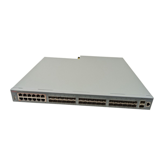
Chapter 5: Installing the VSP 4450GSX- PWR+ series Installation checklist Use this checklist to install the VSP 4450GSX-PWR+and VSP 4450GSX-DC. Task Description Install the VSP 4450GSX series. You can install the switch in two ways: • Installing the Virtual Services Platform 4000 on a table or shelf on page 23 •... - Page 18 Installing the VSP 4450GSX-PWR+ series 1. 12 10/100/1000 Base TX RJ-45 ports with PoE+ 2. 36 100/1000 Mbps SFP ports 3. two 1/10G SFP + ports Figure 1: VSP 4450GSX-PWR+ 1. USB 2.0 port Note: The VSP 4450GSX-PWR+ model does not require a USB device in the USB port for normal operation.
-
Page 19: Electrostatic Discharge
Electrostatic discharge Note: The VSP 4450GSX-DC model does not require a USB device in the USB port for normal operation. The USB port can be used for additional storage using USB memory stick. No log messages are generated when you plug or unplug the USB from the VSP 4450GSX-DC. 2. -
Page 20: Preventing Electrostatic Damage In New Cable Installations
Installing the VSP 4450GSX-PWR+ series • Do not remove the wrist or ankle strap until the installation is complete. Preventing electrostatic damage in new cable installations With new cable installations, you are recommended to use an ESD discharge cable to reduce the potential for damage from static, that can build up in cables. -
Page 21: Environmental Requirements
Environmental requirements Table 3: Physical specifications Specifications 4450GSX-PWR+ 4450GSX-DC Height 4.4 cm. – 1U 4.4 cm. – 1U Width 44 cm. 44 cm. Depth 43.6 cm. 43.68 cm. Weight 17.2lbs (7.80 kg) with 1 PSU 17.2lbs (7.80 kg) with 1 PSU installed. -
Page 22: Airflow Direction
Installing the VSP 4450GSX-PWR+ series Environmental requirement Virtual Services Platform 4000 models • Adequate clearance at the front and rear of the switch for access to cables. Warning: To avoid bodily injury from hazardous electrical shock and current, never remove the top of the device. -
Page 23: Installing The Virtual Services Platform 4000 On A Table Or Shelf
Installing the Virtual Services Platform 4000 on a table or shelf d. The China RoHS paper Installing the Virtual Services Platform 4000 on a table or shelf You can install a single VSP 4000 switch on any flat surface. The surface must support the combined weight of the switch and attached cables (from 15 and 20 pounds [7 to 9 kilograms]). -
Page 24: Installing The Virtual Services Platform 4000 In An Equipment Rack
Installing the VSP 4450GSX-PWR+ series Installing the Virtual Services Platform 4000 in an equipment rack To install an VSP 4000 switch in an equipment rack, perform this procedure. Note: A factory-supplied 4450GSX series switch has a USB port but no USB device or cover. -
Page 25: Cable Requirements For The Virtual Services Platform 4000
Cable requirements for the Virtual Services Platform 4000 2. Slide the switch into the rack as illustrated. 3. Insert and tighten the rack-mount screws. Cable requirements for the Virtual Services Platform 4000 The following table describes the cables required for a the VSP 4000 switch. Table 5: Switch cable requirements Required Cable Description... -
Page 26: Installation And Removal Of Small Form Factor Pluggable (Sfp) Transceivers
Installing the VSP 4450GSX-PWR+ series Required Cable Description Cabling Standard, ANSI/TIA/EIA 568-B fitted with an RJ-45 Module jack. 10/100Base TX Ports The interconnect cabling for 10BaseT Ethernet must conform to Cat3, Cat4, Cat5 (or better) UTP cabling for distances up to 100 meters. -
Page 27: Removing Sfp Transceivers
RJ-45 connector pin assignments Removing SFP transceivers Remove SFP transceivers by performing this procedure. 1. Disconnect the network fiber cable from the transceiver. 2. Use the locking mechanism on the transceiver to release it. The locking mechanism varies from model to model as illustrated below. 3. -
Page 28: Console Port Pin Assignments
Installing the VSP 4450GSX-PWR+ series Table 6: PWR+ RJ-45 connector pin assignments Connector Pin Number Signal Description RX+/power– Receive Data+/power– RX–/power– Receive Data–/power– TX+/power+ Transmit Data+/power+ Not applicable Not applicable Not applicable Not applicable TX–/power+ Transmit Data–/power+ Not applicable Not applicable... -
Page 29: Installing The Virtual Services Platform 4000 Power Supply
Installing the Virtual Services Platform 4000 power supply Table 8: RJ–45 Console port pin assignments Connector Pin Number Signal Ready to send (RTS) — optional Data terminal ready (DTR) — optional, can swap or link with pin 8 Transmit data (TXD) — mandatory Carrier detect (DCD) —... -
Page 30: Power Supply Power Specifications For The Vsp 4450Gsx Series Switches
Installing the VSP 4450GSX-PWR+ series Important: You can hot swap power supplies while the switch is operational. One power supply is required for continued switch operation. PoE+ load reductions can occur if you remove one power supply while the switch is operating with dual power supplies. - Page 31 Installing the Virtual Services Platform 4000 power supply Figure 5: IEC 60320 C16 connector Power over Ethernet Plus (PoE+) specifications Table 9: VSP 4450GSX-PWR+ PoE+ specifications Maximum PoE+ W Average PoE+ W on 12 ports 835W with one power supply 17.8W or 32.4W (802.3.at) —...
-
Page 32: Connect Ac Power
Installing the VSP 4450GSX-PWR+ series Table 11: DC power supply specifications Description DC-DC-12V-300 W Output power 300 W Input voltage 48 V DC Input current 10 A Output voltage 12 V DC Output current 25 A Mean time between failures... -
Page 33: Connect Power To The Rear Panel
Connect AC power Country and Plug Specification Specifications Typical Plug • Harmonized cord (HAR marking on the outside of the cord jacket to comply with the CENELEC Harmonized Document HD-21) United States of America, Canada, and Japan: • 100 or 120VAC •... - Page 34 Installing the VSP 4450GSX-PWR+ series Figure 6: Connecting AC power to the rear panel Warning: Disconnecting the AC power cord is the only way to turn off AC power to the VSP 4000. Always connect the AC power cord in a quickly and safely accessible location in case of an emergency.
- Page 35 Connect AC power CP1 [03/24/14 18:39:04.932:UTC] 0x00010813 00000000 GlobalRouter HW INFO System shutdown initiated from CLI CP1 [03/24/14 18:39:06.000] LifeCycle: INFO: Stopping all processes CP1 [03/24/14 18:39:08.000] LifeCycle: INFO: All processes have stopped CP1 [03/24/14 18:39:08.000] LifeCycle: INFO: All applications shutdown, starting power down sequence INIT: Sending processes the TERM signal Stopping OpenBSD Secure Shell server: sshdno /usr/sbin/sshd found;...
-
Page 36: Led State Definitions
Installing the VSP 4450GSX-PWR+ series LED state definitions The figures and tables in the following sections describe the LEDs on the Virtual Services Platform 4000 Series switches. The tables describe LED operation for a switch that finishes the power-on self-test. -
Page 37: Port Led State Indicators
LED state definitions Note: Indicator states are applicable to all models of VSP 4000 switches. Table 14: Switch LED state indicators Label Color and Status Description Green (solid) The switch is receiving power either from the primary or secondary power supply. Normal operation. The switch is not receiving power and not operating. - Page 38 Installing the VSP 4450GSX-PWR+ series • Link indicates the presence of an Ethernet link. • Speed indicates the port speed (for example, 10 Mb/s, 100 Mb/s, 1000 Mb/s). Table 15: RJ-45 Port LED state indicators Label Color and Status Description...
-
Page 39: Software Restrictions
Software restrictions Note: When you remove an optic or a copper or fiber cable from combo ports (47 and 48) in VSP4850GTS or VSP4850GTS-PWR, the port Link/Activity LEDs graphically represented in EDM do not reflect the correct LED status on the switch. The port Link/Activity LEDs in EDM remain solid green even after an automatic refresh of EDM. -
Page 40: Chapter 6: Translations Of Safety Messages
Chapter 6: Translations of safety messages Caution: When you mount this device in a rack, do not stack units directly on top of one another. You must secure each unit to the rack with appropriate mounting brackets. Mounting brackets cannot support multiple units. Important: Achtung: Wenn diese Einheit in einem Rack montiert wird, muß... - Page 41 Caution: If you are not installing a module in the slot, be sure to keep the metal cover plate in place over the slot. Removing the cover plate impedes airflow and proper cooling of the unit. Important: Achtung: Wenn Sie kein Modul im Schacht verwenden, muß die Metallabdeckung über dem Schacht montiert sein.
- Page 42 Translations of safety messages Warning: Disconnecting the AC power cord is the only way to turn off AC power to this device. Always connect the AC power cord in a quickly and safely accessible location in case of an emergency. Important: Warnung: Das Gerät kann nur durch Ziehen des Netzsteckers ausgeschaltet werden.
- Page 43 Verwenden Sie nur Netzkabel mit Schutzerdung. Ohne ordnungsgemäße Schutzerdung besteht für Personen, die den Switch berühren, die Gefahr eines elektrischen Schlages. Eine nichtvorhandene Schutzerdung kann zu sehr starken Abstrahlungen führen. Danger: N'utilisez que des cordons d'alimentation équipés de trajet de mise à la terre. Sans mise à la terre adaptée, vous risquez de recevoir une décharge électrique en touchant le commutateur.
- Page 44 Translations of safety messages Important: 警告: 系 Extreme 池不支持 更 , 只有授 人 才能 行拆卸和更 。 如果您需要更 池, Networks 技 支持部 求帮助。 Important: Advertencia: La batería de litio no puede sustituirse en campo. La extracción y sustitución debe ser realizada exclusivamente por personal autorizado.
Need help?
Do you have a question about the 4450GSX-PWR+ Series and is the answer not in the manual?
Questions and answers