EXTREME SWITCHING 4900 Series Installing Manual
Ethernet routing switch
Hide thumbs
Also See for 4900 Series:
- Quick start configuration (83 pages) ,
- Installation job aid (10 pages) ,
- Manual (63 pages)

Related Manuals for EXTREME SWITCHING 4900 Series


Summary of Contents for EXTREME SWITCHING 4900 Series
- Page 1 Installing Ethernet Routing Switch 4900 Series Release 7.5 NN47212-301 Issue 05.03 February 2018...
- Page 2 © REPRESENT THAT YOU HAVE THE AUTHORITY TO BIND SUCH 2018, Extreme Networks, Inc. ENTITY TO THESE TERMS OF USE. IF YOU DO NOT HAVE SUCH All Rights Reserved. AUTHORITY, OR IF YOU DO NOT WISH TO ACCEPT THESE Notice TERMS OF USE, YOU MUST NOT ACCESS OR USE THE HOSTED SERVICE OR AUTHORIZE ANYONE TO ACCESS OR While reasonable efforts have been made to ensure that the...
- Page 3 including any code and software unless expressly authorized by THE PERSONAL USE OF A CONSUMER OR OTHER USES IN Extreme Networks. Unauthorized reproduction, transmission, WHICH IT DOES NOT RECEIVE REMUNERATION TO: (I) ENCODE dissemination, storage, and or use without the express written VIDEO IN COMPLIANCE WITH THE AVC STANDARD (“AVC consent of Extreme Networks can be a criminal, as well as a civil VIDEO”) AND/OR (II) DECODE AVC VIDEO THAT WAS ENCODED...
- Page 4 For additional information on Extreme Networks trademarks, please see: http://www.extremenetworks.com/company/legal/...
-
Page 5: Table Of Contents
Subscribing to service notifications Chapter 2: New in this document.................. 10 Chapter 3: Preinstallation checklist.................. 11 Chapter 4: Installation preparation.................. 13 ................ 13 Ethernet Routing Switch 4900 Series models ..................... 14 Common hardware features .................... 15 Universal Serial Bus ports .................. - Page 6 Port LED state indicators Chapter 6: Installation reference................... 50 .................... 50 Console port pin assignments .............. 50 RJ-45 connector pin assignments for PoE switches Chapter 7: Translations of safety messages................ 52 ........................ 52 Safety messages February 2018 Installing Ethernet Routing Switch 4900 Series...
-
Page 7: Chapter 1: Preface
Chapter 1: Preface Purpose This document provides the information and procedures required to install the hardware, software, cabling, and power for the Extreme Networks Ethernet Routing Switch 4900 Series. Unless otherwise indicated, this information applies to: • ERS 4950GTS • ERS 4926GTS •... -
Page 8: Getting Help
Use the online service request system to create a service request. Chat with live agents to get answers to questions, or request an agent to connect you to a support team if an issue requires additional expertise. February 2018 Installing Ethernet Routing Switch 4900 Series... -
Page 9: Extreme Networks Documentation
5. Type your job title. 6. Select the industry in which your company operates. 7. Confirm your geographic information is correct. 8. Select the products for which you would like to receive notifications. 9. Click Submit. February 2018 Installing Ethernet Routing Switch 4900 Series... -
Page 10: Chapter 2: New In This Document
Chapter 2: New in this document There are no feature changes in this release. February 2018 Installing Ethernet Routing Switch 4900 Series... -
Page 11: Chapter 3: Preinstallation Checklist
Chapter 3: Preinstallation checklist Before you install the Ethernet Routing Switch 4900 Series, make sure that you complete the tasks in the preinstallation checklist. Task Description Review the technical specification for the For the physical, electrical, and switch. Make sure that the area where... - Page 12 The ground path must be permanent and must not exceed 1 Ohm of resistance from the rack to the grounding electrode. Installing the switch in an equipment rack on page 25. February 2018 Installing Ethernet Routing Switch 4900 Series...
-
Page 13: Chapter 4: Installation Preparation
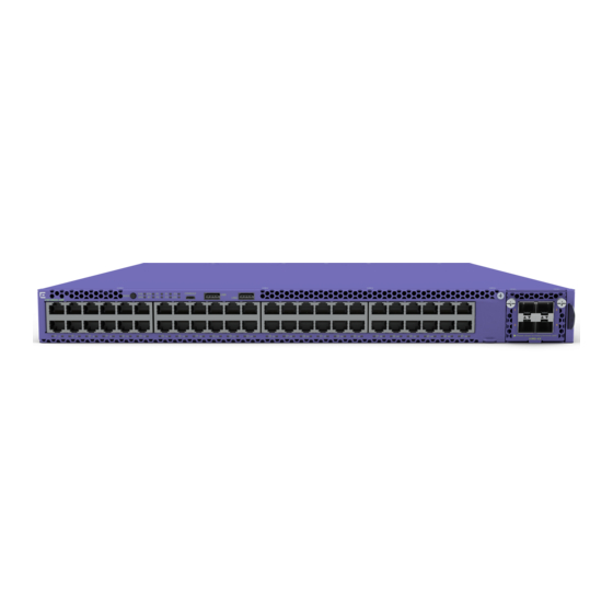
This section provides information about the switches in Ethernet Routing Switch 4900 Series. Ethernet Routing Switch 4900 Series models The following table lists the different Ethernet Routing Switch 4900 Series models and the key features for each switch. Switch Model... -
Page 14: Common Hardware Features
Depending on the switch model, a 250 W or 1025 W PSU and .5 m stacking cable is provided for all switches. Common hardware features The following hardware features are part of all switches in ERS 4900 Series: • Standard ERS 19 inch rack mount hole pattern allowing horizontal or vertical, flush or offset, front or rear mount options •... -
Page 15: Universal Serial Bus Ports
The port labeled AUX is disabled. - power supply units - one Kensington Lock slot located on the left side, near the back end of the chassis The following figure illustrates ERS 4900 Series rear panel. 1. Stack up connector 2. Stack down connector 3. -
Page 16: Electrostatic Discharge Prevention
With new cable installations, you should use an ESD discharge cable to reduce the potential for damage from static that can build up in cables. See the following figure. Figure 3: ESD cable February 2018 Installing Ethernet Routing Switch 4900 Series... -
Page 17: Technical Specifications
(see table, AC power specifications) • At least 2 inches (5.08 cm) on each side of the switch unit for ventilation • Cables should be dressed to prevent blocking air flow. February 2018 Installing Ethernet Routing Switch 4900 Series... -
Page 18: Power Specifications
792.53 3.57 308.88 PWR+ 1025 W 200–240 VAC 816.03 3.78 342.32 1025 W 100–110 VAC 825.11 7.55 413.56 1025 W 100–110 VAC 839.64 7.73 424.24 The following table provides typical power consumption. February 2018 Installing Ethernet Routing Switch 4900 Series... -
Page 19: Mtbf Values
2 PSU 1440 1025 110–240VAC PWR+ 1 PSU MTBF values The following table lists the MTBF values for the switches in ERS 4900 Series in combination with one or two PSUs. Model Number of PSUs Power Supply rating MTBF (hours) 4926GTS... -
Page 20: Power Supply Cords
The switch models that support PoE use 1025 W power supply, this power supply is unique to ERS 4900 Series. The power adapter on 1025 W power supply utilizes an IEC 60320 C16 connector. The IEC 60320 C16 connector accepts only an IEC 60320 C15 mating power cable and the IEC 60320 C16 connector utilizes a keying feature which prevents IEC 60320 C13 connector from being inserted in C16 socket. - Page 21 Power cord 2.5 m IEC C13 to JIS Japan 8303 AA0020101-E6 Power cord 2.5 m IEC C13 to NBR Brazil 14136 (IEC 60906-1) AA0020104-E6 Power cord 2.5 m IEC C13 to SEV Switzerland 1011 Table continues… February 2018 Installing Ethernet Routing Switch 4900 Series...
-
Page 22: Verifying The Package Contents
IRAM 2073 Verifying the package contents For each Ethernet Routing Switch 4900 Series, verify the package contents with the items in the following figure to ensure you have received all components. If any components are missing, contact the vendor where you purchased the switch. -
Page 23: Optional Rack-Mounting Equipment
If you plan to rack-mount the switch, ensure the following equipment is available: Table 10: Optional equipment Optional equipment Order code Equipment Spare Rack Mount 700512595 Kit—used as a replacement rack mount kit. 19 inch Rack Mount February 2018 Installing Ethernet Routing Switch 4900 Series... -
Page 24: Power Supply Unit Specifications
Check the front-panel LEDs as the device is powered on to be sure the PWR LED is lit. If not, check that the power cable is correctly plugged in. Checking Light Emitting Diode on the switch on page 46. February 2018 Installing Ethernet Routing Switch 4900 Series... -
Page 25: Chapter 5: Switch Installation
1. Ensure power is disconnected from the switch. 2. Attach a bracket to each side of the switch with the included screws. Attach the brackets in the best position for your specific equipment rack. February 2018 Installing Ethernet Routing Switch 4900 Series... - Page 26 Switch installation Figure 4: Front-mounted rack bracket installation February 2018 Installing Ethernet Routing Switch 4900 Series...
- Page 27 Installing the switch in an equipment rack Figure 5: Rear-mounted rack bracket installation 3. Slide the switch into the rack. 4. Insert and tighten the rack mount screws. February 2018 Installing Ethernet Routing Switch 4900 Series...
- Page 28 Switch installation Figure 6: Front-mounted rack installation February 2018 Installing Ethernet Routing Switch 4900 Series...
-
Page 29: Installing Optional Four-Post Rack-Mount Brackets
• Verify that you have all the screws and brackets to assemble and install the four-post rack mount kit. • Tools: - Phillips screwdriver to attach brackets to the switch and the switch to the rack. - Hex wrench to assemble and attach the optional four-post rack-mount brackets. February 2018 Installing Ethernet Routing Switch 4900 Series... - Page 30 Figure 8: Four-post rack-mount kit assembly Procedure 1. Attach a front bracket to each guide bracket with four 8.5 mm length flat head machine screws. 2. Attach the guide brackets to the switch chassis. February 2018 Installing Ethernet Routing Switch 4900 Series...
- Page 31 Use four M4 x 5.5 mm undercut flat-head hex machine screws to attach the rear of each guide bracket to the switch chassis. b. Verify that the rear screws sit flush in the guide brackets. February 2018 Installing Ethernet Routing Switch 4900 Series...
- Page 32 Slide a rear mounting bracket into each guide bracket channel until flush with the rear rack posts. b. Secure the rear mounting brackets to the switch chassis with the pan-head screws. February 2018 Installing Ethernet Routing Switch 4900 Series...
-
Page 33: Installing The Secondary Power Supply
To prevent damage from electrostatic discharge, always wear an antistatic wrist strap connected to an ESD jack when performing maintenance on a switch. Ensure that the wrist strap makes contact with your skin. February 2018 Installing Ethernet Routing Switch 4900 Series... -
Page 34: Connecting A Transceiver To The Switch Or Switch Stack
4. Insert the transceiver into the proper module on the switch. Apply a light pressure to the transceiver until it clicks and locks into position in the module. 5. Remove the dust cover from the transceiver optical bores. Example The following graphic shows an SFP transceiver. February 2018 Installing Ethernet Routing Switch 4900 Series... -
Page 35: Removing Of Sfp Transceivers
Remove SFP transceivers by performing this procedure. 1. Disconnect the network fiber cable from the transceiver. 2. Use the locking mechanism on the transceiver to release it. The locking mechanism varies from model to model as illustrated below. February 2018 Installing Ethernet Routing Switch 4900 Series... -
Page 36: Supported Optical Devices
This table is informational only—not all Ethernet switching and routing products support all the SFPs listed here. Important: The attainable cable length can vary depending on the quality of the fiber-optic cable used. February 2018 Installing Ethernet Routing Switch 4900 Series... - Page 37 10 Gigabit ports 10GBASE-ZR/ZW SFP+ 70 km, 1550 nm SMF AA1403016–E6 10GBASE-T SFP+ up to 30 meters AA1403043–E6 10GBASE CWDM DDI SFP+ (40 40 km, 1471 to 1611 nm AA1403153–E6 to AA1403160–E6 Table continues… February 2018 Installing Ethernet Routing Switch 4900 Series...
-
Page 38: Cable Requirements
To view the End of Sale notices, go to one of the following Websites: • The Avaya Support website at http://support.avaya.com/. • The Extreme Networks Website at https://extremeportal.force.com/. Cable requirements The following table describes the cables required for Ethernet Routing Switch 4900 Series. Table 14: Stacking cables Description Material code Stacking cable 0.5 m... -
Page 39: Stacking
Stacking The switch provides fail-safe stackability. You can connect up to eight 4900 series devices in a stack to provide uninterrupted connectivity for up to 400 ports. You can manage the stack as a single unit. Stack connector The stack connector is a component of the switch back panel and consists of the Unit Select switch, Cascade Down connector, and Cascade Up connector. - Page 40 3, this continues until the maximum stack configuration (up to eight units) is reached. If another unit in the stack is designated as the base unit, the new base unit keeps its originally designated unit number in the stack. February 2018 Installing Ethernet Routing Switch 4900 Series...
-
Page 41: Redundant Cascade Stacking
If one path is interrupted, the data travels over the remaining path at half the normal inter- switch bandwidth. The following figure shows a typical example of a stack configuration reacting to a failed connection in the stack configuration. February 2018 Installing Ethernet Routing Switch 4900 Series... -
Page 42: Connecting Switches In A Stack
Connect a switch to the next unit in the stack through a cascade cable. The stack parameters are associated with the base unit, the physical stack order depends on the base unit position and February 2018 Installing Ethernet Routing Switch 4900 Series... -
Page 43: Stack Configurations
Cascade Down configuration is recommended because many network management software packages assume a cascade down (stack down) configuration. Before you begin Order the appropriate Ethernet Routing Switch 4900 Series cascade cables to ensure fail-safe stacking. For more information, see Cable requirements on page 38. - Page 44 Cascade Up connector of the base unit terminates in the Cascade Down connector of the last unit physically at the top of the stack. The stack is wired upward through the February 2018 Installing Ethernet Routing Switch 4900 Series...
- Page 45 1. Base Unit 2. Last Unit 3. Cascade or Stack Cable 4. Cascade/Stack Cable (Return cable to make stack resilient. Use longer Stack Cable if required) Figure 13: Cascade Up (Stack Up) configuration February 2018 Installing Ethernet Routing Switch 4900 Series...
-
Page 46: Replacing Or Adding A Stack Unit
Checking Light Emitting Diode on the switch The figures and tables in the following sections describe the LEDs on the switch. The tables describe LED operation for a switch that finishes the power-on self-test. February 2018 Installing Ethernet Routing Switch 4900 Series... -
Page 47: Switch Led State Indicators
The switch was not allowed to join the stack. Check the switch logs. The switch is not the base unit or temporary base unit, or the switch is operating in stand-alone mode. February 2018 Installing Ethernet Routing Switch 4900 Series... -
Page 48: Port Led State Indicators
Color and Status Description In Use Green, Blink Not applicable. Green, Steady The SFP port and the transmit port are active. Amber, Blink Not applicable. Amber, Steady SFP Installed—TX Port Inactive Table continues… February 2018 Installing Ethernet Routing Switch 4900 Series... - Page 49 100BaseTX) the port link LED may indicate a link, but the switch does not establish a link. Connect ports using the same set speed or use auto-negotiation on each switch. February 2018 Installing Ethernet Routing Switch 4900 Series...
-
Page 50: Chapter 6: Installation Reference
Chapter 6: Installation reference This section provides reference information for the ERS 4900 Series. Console port pin assignments The following table describes the console port pin assignments. Table 20: RJ–45 Console port pin assignments Connector Pin Number Signal Ready to send (RTS) — optional Data terminal ready (DTR) —... - Page 51 Pin Number Signal Description RX+/power– Receive Data+/power– RX–/power– Receive Data–/power– TX+/power+ Transmit Data+/power+ Not applicable Not applicable Not applicable Not applicable TX–/power+ Transmit Data–/power+ Not applicable Not applicable Not applicable Not applicable February 2018 Installing Ethernet Routing Switch 4900 Series...
-
Page 52: Chapter 7: Translations Of Safety Messages
Se il dispositivo viene installato in un rack, non impilare le unità direttamente una sull’altra. Ogni unità deve essere fissata al rack con le staffe di montaggio appropriate. Le staffe di montaggio non sono state progettate per supportare più unità. February 2018 Installing Ethernet Routing Switch 4900 Series... - Page 53 Attenzione: Se nello slot non vengono installati moduli, assicurarsi di mantenere la piastra di copertura metallica in sede sopra lo slot. La rimozione della piastra impedisce la ventilazione e il corretto raffreddamento dell’unità. February 2018 Installing Ethernet Routing Switch 4900 Series...
- Page 54 Important: Vorsicht: Verwenden Sie nur Netzkabel mit Schutzerdung. Ohne ordnungsgemäße Schutzerdung besteht für Personen, die den Switch berühren, die Gefahr eines elektrischen Schlages. Eine nichtvorhandene Schutzerdung kann zu sehr starken Abstrahlungen führen. February 2018 Installing Ethernet Routing Switch 4900 Series...
- Page 55 Senza un’adeguata messa a terra, chiunque tocchi lo switch corre il rischio di ricevere una scossa elettrica. L’assenza di un percorso per la messa a terra verso lo switch può comportare un eccesso di emissioni. February 2018 Installing Ethernet Routing Switch 4900 Series...
- Page 56 Index Console pin assignments .............50 Universal Serial Bus (USB) ports .........15 USB ports ................February 2018 Installing Ethernet Routing Switch 4900 Series...
Need help?
Do you have a question about the 4900 Series and is the answer not in the manual?
Questions and answers