EXTREME SWITCHING 5900 Series Installing
Ethernet routing switch
Hide thumbs
Also See for 5900 Series:
- Installing (76 pages) ,
- Installation job aid (19 pages) ,
- Quick start configuration (83 pages)

Related Manuals for EXTREME SWITCHING 5900 Series


Summary of Contents for EXTREME SWITCHING 5900 Series
- Page 1 Installing Ethernet Routing Switch 5900 Series Release 7.8 9036210-00 Rev AA February 2020...
- Page 2 © 2017-2020, Extreme Networks, Inc. All Rights Reserved. Legal Notice Extreme Networks, Inc. reserves the right to make changes in specifications and other information contained in this document and its website without prior notice. The reader should in all cases consult representatives of Extreme Networks to determine whether any such changes have been made.
-
Page 3: Table Of Contents
...................... 38 Connecting AC Power Chapter 5: Switch Installation.................... 40 ............ 41 Installing ERS 5900 Series Switch in an Equipment Rack ....... 43 Installing Ethernet Routing Switch 59100 Series Switches in an Equipment Rack ........ 47 Installing the Switch Using Optional Four-Post Rack-Mount Brackets ................ 51... - Page 4 Contents ..................... 72 ERS 5900 Series PoE Chapter 7: Translations of Safety Messages................ 74 ........................ 74 Safety Messages Appendix A: Regulatory and Compliance Information............ 78 .............. 78 Federal Communications Commission (FCC) Notice ...................... 78 Industry Canada Notice ........................ 79 Class A ITE Notice .......................
-
Page 5: Chapter 1: About This Document
Extreme Networks publications. Purpose This document provides the information and procedures required to install the hardware, software, cabling, and power for the Extreme Networks Ethernet Routing Switch 5900 Series. Unless otherwise indicated, this information applies to: • ERS 5928MTS-uPWR •... - Page 6 Brackets ( [ ] ) indicate optional elements in syntax descriptions. Do not type the brackets when you enter the command. For example, if the command syntax is show clock [detail], you can enter either show clock or show clock detail. Table continues… February 2020 Installing ERS 5900 Series...
-
Page 7: Documentation And Training
Documentation and Training Find Extreme Networks product information at the following locations: Current Product Documentation Release Notes Hardware/software compatibility matrices for Campus and Edge products Supported transceivers and cables for Data Center products February 2020 Installing ERS 5900 Series... -
Page 8: Getting Help
You can subscribe to email notifications for product and software release announcements, Vulnerability Notices, and Service Notifications. 1. Go to www.extremenetworks.com/support/service-notification-form. 2. Complete the form (all fields are required). 3. Select the products for which you would like to receive notifications. February 2020 Installing ERS 5900 Series... -
Page 9: Providing Feedback
• Access the feedback form at https://www.extremenetworks.com/documentation-feedback/. • Email us at documentation@extremenetworks.com. Provide the publication title, part number, and as much detail as possible, including the topic heading and page number if applicable, as well as your suggestions for improvement. February 2020 Installing ERS 5900 Series... -
Page 10: Chapter 2: New In This Document
Regulatory and Compliance Information This document is updated with the Regulatory and Compliance information from Regulatory Reference for Ethernet Routing Switch 4900 Series, which is now obsolete. For more information, Regulatory and Compliance Information on page 78. February 2020 Installing ERS 5900 Series... -
Page 11: Chapter 3: Preinstallation Checklist
Chapter 3: Preinstallation Checklist Before you install the ERS 5900 Series, make sure that you complete the tasks in the preinstallation checklist. Task Description Review the technical specification for For the physical, electrical, and the switch. Make sure that the area... - Page 12 Ensure that the rack is grounded to the same grounding electrode used by the power service in the area. The ground path must be permanent and must not exceed 1 Ohm of resistance from the rack to the grounding electrode. February 2020 Installing ERS 5900 Series...
-
Page 13: Chapter 4: Installation Preparation
Chapter 4: Installation Preparation Ethernet Routing Switch 5900 Series Models The following table lists the different ERS 5900 Series models and the key features for each switch. Table 3: ERS 5900 Series models Switch Model Key features Part Number ERS 5928MTS-uPWR •... - Page 14 AL5900A3F-E6 (no PC) ports • Non-PoE • Layer 2/Layer 3 • Stackable Ethernet switch • 1 rack unit (U) high • Uses modular power supply units and has two field- serviceable power supply Table continues… February 2020 Installing ERS 5900 Series...
- Page 15 Ethernet Routing Switch 5900 Series Models Switch Model Key features Part Number receptacles, which support 450 W AC power supply modules. ERS 5952GTS-PWR+ • 48 10/100/1000 Base-T RJ-45 AL590004A-E6 (no PSU, no PC) ports with 802.3at PoE+ AL5900A4B-E6 (no PC) •...
- Page 16 Front to Back cooling (for example, AL5900E4F-E6). Common Hardware Features The following hardware features are part of all ERS 5900 Series switches: • One RJ-45 RS-232 Console connection at the front (note jack orientation) • Two FRU Fan Tray modules Note: ERS 59100GTS and ERS 59100GTS-PWR+ support four Fan Tray modules.
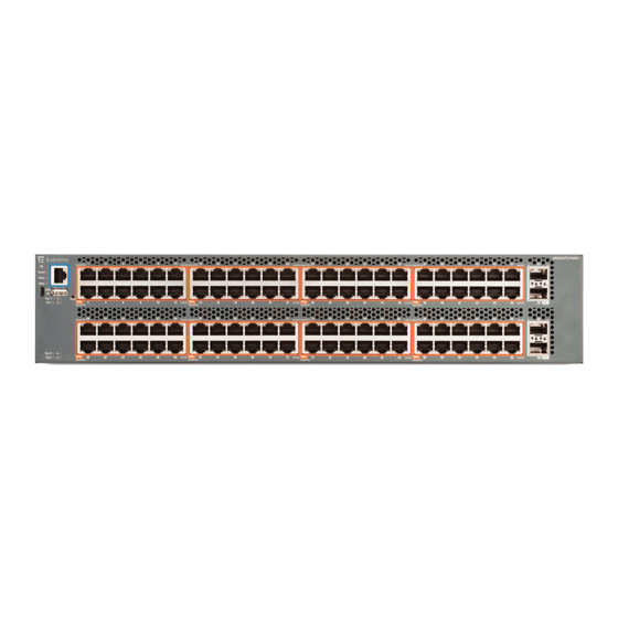
- Page 17 Ethernet Routing Switch 5900 Series Models 1. Console port 2. USB 2.1 Type-A port 3. LED display The following figure shows the rear panel of the ERS 5952GTS switch. 1. Diagnostic ports (SDN port (labelled as AUX cannot be enabled) and out-of-band management port) 2.
- Page 18 Universal Serial Bus Ports on the Ethernet Routing Switch 5900 Series The ERS 5900 Series switches include a USB Type A port on the front panel adjacent to the console port, as well as a micro-USB Type B port. The USB Type A port enables switch administrators to perform tasks that were previously completed through TFTP with a commonly available USB Mass Storage Device (also known as a flash drive or thumb drive).
-
Page 19: Electrostatic Discharge Prevention
• Do not remove the wrist or ankle strap until the installation is complete. With new cable installations, you should use an ESD cable to reduce the potential for damage from static that can build up in cables. See the following figure. Figure 1: ESD cable February 2020 Installing ERS 5900 Series... -
Page 20: Technical Specifications
Installation Preparation Technical Specifications The following table provides the technical specifications for the individual switches in the Ethernet Routing Switch 5900 Series. Ensure that the area where you install the switch and where it operates meets these requirements. Warning: To avoid bodily injury from hazardous electrical shock and current, never remove the top of the device. - Page 21 -304.8 to 12,192 m (-1,000 to 40,000 feet) above sea level Acoustic Noise At 25°C Ambient Temperature, less than 52 dBA typical, at 50°C, less than 60 dBA. The system should never exceed 70dBA. Table continues… February 2020 Installing ERS 5900 Series...
-
Page 22: Power Specifications
• Adequate clearance is allotted at the front and rear of the switch for access to cables. Power Specifications This section provides the following specifications for Ethernet Routing Switch 5900 Series. The following table describes the AC power specifications. Table 7: AC power specifications... - Page 23 4 PSU 1400 200–240 3218.9 14.1 322.1 1099.0 W/PSU 3 PSU 3227.7 14.1 330.5 1127.6 2 PSU 3158.7 13.8 353.8 1203.7 1 PSU 1643.3 7.2 202.8 692.0 The following table provides typical power consumption. February 2020 Installing ERS 5900 Series...
- Page 24 1 PSU ERS 5928GTS-uPWR 2 PSU 1000 100–120 1440 1 PSU 2 PSU 1400 200–240 1440 1 PSU 1200 ERS 5952GTS-PWR+ 2 PSU 1000 100–120 1440 1 PSU 2 PSU 1400 200–240 1440 Table continues… February 2020 Installing ERS 5900 Series...
-
Page 25: Mtbf Values
1440 1 PSU 1200 MTBF Values The following table lists the MTBF values for the switches in Ethernet Routing Switch 5900 Series when two or four fans are used in combination with PSUs. Model Number of PSUs Power Supply rating... -
Page 26: Power Supply Cords
Ethernet Routing Switch 5900 Series models that support PoE use 1000 W or 1400 W power supply. This power supply is unique to ERS 5900 Series. The power adapter on 1000 W or 1400 W power supply utilizes an IEC 60320 C16 connector. The IEC 60320 C16 connector accepts only an IEC 60320 C15 mating power cable and the IEC 60320 C16 connector utilizes a keying feature which prevents IEC 60320 C13 connector from being inserted in C16 socket. - Page 27 Back to Front Airflow ERS 5928GTS-PWR+ AL1905A3F-E6 Front to Back Airflow ERS 5928GTS-PWR+ AL1905A3B-E6 Back to Front Airflow ERS 5928GTS-uPWR AL1905A3F-E6 Front to Back Airflow ERS 5928GTS-uPWR AL1905A3B-E6 Back to Front Airflow Table continues… February 2020 Installing ERS 5900 Series...
- Page 28 Power cord 2.5 m IEC C13 to AS Australia 3112 AA0020069E6 Power cord 2.5 m IEC C13 to JIS Japan 8303 AA0020101-E6 Power cord 2.5 m IEC C13 to NBR Brazil 14136 (IEC 60906-1) Table continues… February 2020 Installing ERS 5900 Series...
- Page 29 Power cord 2.5 m IEC C15 to North America NEMA L6-15P TWIST LOCK AA0020109-E6 Power cord 2.5 m IEC C15 to India BS-546 AA0020110-E6 Power cord 2.5 m IEC C15 to Argentina IRAM 2073 February 2020 Installing ERS 5900 Series...
- Page 30 ERS 5928MTS-uPWR, ERS 5928GTS, ERS ERS 5900 switch package contents on page 31 5928GTS-PWR+, ERS 5928GTS-uPWR, ERS 5952GTS, and ERS 5952GTS-PWR+ ERS 59100GTS and ERS 59100GTS-PWR+ ERS 59100 switch package contents on page 32 February 2020 Installing ERS 5900 Series...
- Page 31 Verify the Package Contents Ethernet Routing Switch 5900 Series Package Contents February 2020 Installing ERS 5900 Series...
-
Page 32: Cooling Fans And Power Supplies
Table 14: Supported number of fan trays and power supply units on page 33 and at least one power supply unit. To provide redundancy, the supported number of power supplies and fan trays can be installed. February 2020 Installing ERS 5900 Series... -
Page 33: Cooling Fan Trays
The following figure shows cooling fan trays. Figure 2: Fan tray February 2020 Installing ERS 5900 Series... -
Page 34: Power Supply Compatibility With Cooling Fans
You can install two or four power supplies for redundancy and load sharing. You can hot-swap power supplies for nonstop, uninterrupted switch operation. Power Supply Monitoring For enhanced monitoring, power supplies send information to the switch software about the type (AC and airflow mode). February 2020 Installing ERS 5900 Series... -
Page 35: Installing The Fan Trays And Power Supply
33. The following figures show fan trays and power supply location: Figure 4: ERS 59100GTS and ERS 59100GTS-PWR+ rear panel Figure 5: ERS 5900 Series rear panel Fan Tray 2 Fan Tray 1 Power Supply Unit 1 (PS 1) - Page 36 4. Verify that each power supply is fully seated in the slot and securely clipped in place. Example The following figures show how to properly insert the cooling fan trays and power supplies into your switch. February 2020 Installing ERS 5900 Series...
- Page 37 Cooling Fans and Power Supplies Figure 6: Installing the fan trays and power supplies in ERS 59100GTS and ERS 59100GTS-PWR+ February 2020 Installing ERS 5900 Series...
-
Page 38: Connecting Ac Power
Installation Preparation Figure 7: Installing the fan trays and power supplies in ERS 5900 Series Next steps After you install the two fan trays and at least one power supply, you can install and connect power to the switch. Connecting AC Power Perform the following procedure to connect an AC power source to the switch. - Page 39 The only way to turn off the switch is to disconnect the power. Always connect the AC power cord in a location that can be reached quickly and safely in case of an emergency. February 2020 Installing ERS 5900 Series...
-
Page 40: Chapter 5: Switch Installation
47 mount brackets and then, slide the switch. The brackets secure the chassis and prevent it from sliding around during vibration or when inserting or extracting transceivers. February 2020 Installing ERS 5900 Series... -
Page 41: Installing Ers 5900 Series Switch In An Equipment Rack
Installing ERS 5900 Series Switch in an Equipment Rack Installing ERS 5900 Series Switch in an Equipment Rack About this task Use the following procedure to install ERS 5900 Series switches in an equipment rack. Before you begin Tool requirements •... - Page 42 Switch Installation Figure 9: Rear-mounted rack bracket installation 3. Slide the switch into the rack. 4. Insert and tighten the rack mount screws. Figure 10: Front-mounted rack installation February 2020 Installing ERS 5900 Series...
-
Page 43: Installing Ethernet Routing Switch 59100 Series Switches In An Equipment Rack
Equipment Rack About this task Use the following procedure to install Ethernet Routing Switch 59100 Series in an equipment rack. To install other switches in ERS 5900 Series, see Installing ERS 5900 switch in an equipment rack on page 41. - Page 44 2. Attach a bracket to each side of the switch with the included screws. You have different options for front and rear mounting positions. Attach the brackets in the best position for your specific equipment rack. Figure 12: Front-mounted rack bracket installation February 2020 Installing ERS 5900 Series...
- Page 45 Installing Ethernet Routing Switch 59100 Series Switches in an Equipment Rack Figure 13: Rear-mounted rack bracket installation 3. Slide the switch into the rack. February 2020 Installing ERS 5900 Series...
- Page 46 Switch Installation Figure 14: Front-mounted rack installation February 2020 Installing ERS 5900 Series...
-
Page 47: Installing The Switch Using Optional Four-Post Rack-Mount Brackets
Perform this procedure to assemble and install the four-post rack-mount bracket kit. Before you begin Ensure you have the ERS 5900 Series four-post server rack-mount kit — AL5911001-E6 Tool requirements • Phillips screwdriver to attach brackets to the switch and the switch to the rack. - Page 48 Verify that you have all the screws and brackets to assemble and install the four-post rack mount kit. Figure 16: Four-post rack-mount kit assembly Procedure 1. Attach a front bracket to each guide bracket with four 8.5 mm length flat head machine screws. February 2020 Installing ERS 5900 Series...
- Page 49 Installing the Switch Using Optional Four-Post Rack-Mount Brackets 2. Attach the guide brackets to the switch chassis. Figure 17: Attaching guide brackets to ERS 5900 switch February 2020 Installing ERS 5900 Series...
- Page 50 Test fit the rear mounting brackets in the guide brackets and verify that the rear brackets can slide in the channels. Remove the rear brackets. 3. Install the switch into the equipment rack, temporarily using only the front rack mounts and screws. February 2020 Installing ERS 5900 Series...
-
Page 51: Single And Multiple Switch Arrangements
Figure 20: Attach ERS 5900 switch rear mounting brackets You can proceed with the installation by connecting power and network connections to the switch. Single and Multiple Switch Arrangements This module describes standalone and stacked arrangements. February 2020 Installing ERS 5900 Series... - Page 52 Switch Installation You can stack any of the switches in the ERS 5900 Series. You can connect up to eight switch devices that are in one Rack Unit (RU) height in a stack to provide uninterrupted connectivity for up to 384 ports.
- Page 53 (via the Cascade Down cable) becomes unit 2 (and the next unit is unit 3 and so on), until the maximum stack configuration (up to eight units for an ERS 5900 Series stack and up to four units for an ERS 59100 stack) is reached. If the base unit is changed to another unit in the stack, the new base unit keeps its original unit number in the stack.
- Page 54 In this configuration, the base unit discovers the stack in a cascade down (stack down) direction. The following illustration shows a cascade down (stack down) configuration for ERS 5900 switch series. The ERS 59100 switch can be connected similarly. February 2020 Installing ERS 5900 Series...
- Page 55 4 = 1.0m Cascade/Stack cable (Return cable) Figure 23: ERS 5900 cascade down configuration Note: Return cable length may vary depending on unit spacing. Ensure you order the proper length return cable to provide adequate strain relief. February 2020 Installing ERS 5900 Series...
- Page 56 Unit 2. The stack is wired upward through the units and the system continues to number in this manner throughout the stack. In this configuration, the base unit discovers the stack in a cascade up (stack up) direction. The following illustration shows a cascade up (stack up) configuration. February 2020 Installing ERS 5900 Series...
- Page 57 Figure 24: Cascade up configuration Note: Return cable length may vary depending on unit spacing. Ensure you order the proper length return cable to provide adequate strain relief. For stack installation procedures, see Stack Configuration on page 59. February 2020 Installing ERS 5900 Series...
- Page 58 Redundant Cascade Stacking The ERS 5900 Series switches allow a stack of up to eight units in a ERS 5900 stack. If any single unit fails or if a cable is accidently disconnected, other units in the stack remain operational without interruption.
-
Page 59: Stack Configuration
You can change base unit switches with switches on (hot), but changes do not take affect until switches are rebooted. Selecting a Base Unit About this task This procedure describes the steps to select a base unit. February 2020 Installing ERS 5900 Series... - Page 60 Standard, ANSI/TIA/EIA 568-B fitted with an RJ-45 Module Jack. Console Port Serial cable with a DB-9 female connector on both ends. The maximum length for the console port cable is 25 feet (8.3 meters). Table continues… February 2020 Installing ERS 5900 Series...
-
Page 61: Connecting A Transceiver To The Switch Or Stack
4. Insert the transceiver into the proper module on the switch. Apply a light pressure to the transceiver until it clicks and locks into position in the module. 5. Remove the dust cover from the transceiver optical bores. Job Aid The following graphic shows an SFP transceiver. February 2020 Installing ERS 5900 Series... -
Page 62: Supported Optical Devices
• Install the switch in an equipment rack or on a shelf. • Connect power to the switch. Procedure 1. Locate the status LEDs on the front of the unit; see the following figure. February 2020 Installing ERS 5900 Series... - Page 63 2. View the status LED states to verify that the fan trays and power supplies are installed and operating correctly. You can also verify the status and operating mode of the unit. For status LED state descriptions, see the following table. February 2020 Installing ERS 5900 Series...
- Page 64 The unit formed a partial neighbor with an adjacent unit. Check the Cascade Up and Down cable connections. Note: If rear port mode is enabled, both Up and Down LEDs blink Emerald in synchronization. The Base LED is off. Table continues… February 2020 Installing ERS 5900 Series...
- Page 65 Sapphire (Blinking) The fan tray in position 1, 2, 3, or 4 is front to back airflow and has degraded. Check for a fan failure and replace if necessary. Table continues… February 2020 Installing ERS 5900 Series...
-
Page 66: Ip Address Information Configuration
The port has been disabled by the software. Indicates that the link has been lost. IP Address Information Configuration About this task The following sections contain information necessary to configure IP address parameters on the switch. February 2020 Installing ERS 5900 Series... - Page 67 1. From the console menu, select IP Configuration/Setup. 2. Assign an IP address to the switch. • For a standalone switch, enter a value in the In-Band Switch IP Address field in dotted- decimal notation. February 2020 Installing ERS 5900 Series...
- Page 68 The following table lists the parameters that must be used with any terminal emulation software used to connect to the switch. Table 18: Terminal emulation settings Property Value Baud Rate 9600 bps Data Bits Stop Bits Parity None Flow Control None February 2020 Installing ERS 5900 Series...
- Page 69 • Ensure the terminal from which you ping the switch is on the same network as the switch. Procedure Ping the ERS 5900 Series switch from a terminal or workstation that is on the same network. If the network device sends a ping reply, a message indicates that the specified IP address is alive and can communicate with other devices.
-
Page 70: Chapter 6: Installation Reference
Chapter 6: Installation Reference About this task This section provides reference information for the ERS 5900 Series. Console and Management Connections The left front panel of the switch contains the Status LEDs, Console port, Out of Band Management port, and a USB 2.1 port, as well as a micro-USB Type B port (reserved). -
Page 71: Out Of Band Management Ports
The USB port is a Standard Type-A female USB 2.1 port. The switch provides USB host functionality and can support USB flash drives. RJ-45 Connector Pin Assignments The following section outlines the connector pin assignments for the RJ-45 connectors in the ERS 5900 Series. February 2020 Installing ERS 5900 Series... -
Page 72: Ers 5900 Series Poe
Installation Reference ERS 5900 Series Non-PoE The following table outlines the RJ-45 connector pin assignments in the ERS 5900 Series non-PoE switches. Connector Signal for 10/100Base-T Signal for 10/100Base-T Number MDI configuration MDI-X configuration Output transmit data + Input receive data + (RX+) - Page 73 Signal for 10/100Base-T MDI configuration MDI-X configuration RX+/power+ Receive Data+/power+ RX-/power+ Receive Data-/power+ TX+/power- Transmit Data+/power- Not applicable Not applicable Not applicable Not applicable TX-/power- Transmit Data-/power- Not applicable Not applicable Not applicable Not applicable February 2020 Installing ERS 5900 Series...
-
Page 74: Chapter 7: Translations Of Safety Messages
Chapter 7: Translations of Safety Messages This module contains translations of the safety messages found in the ERS 5900 Series documentation suite. Safety Messages Caution: When mounting this device in a rack, do not stack units directly on top of one another in the rack. - Page 75 Important: Attenzione: Se nello slot non vengono installati moduli, assicurarsi di mantenere la piastra di copertura metallica in sede sopra lo slot. La rimozione della piastra impedisce la ventilazione e il corretto raffreddamento dell’unità. February 2020 Installing ERS 5900 Series...
- Page 76 Important: Vorsicht: Verwenden Sie nur Netzkabel mit Schutzerdung. Ohne ordnungsgemäße Schutzerdung besteht für Personen, die den Switch berühren, die Gefahr eines elektrischen Schlages. Eine nichtvorhandene Schutzerdung kann zu sehr starken Abstrahlungen führen. February 2020 Installing ERS 5900 Series...
- Page 77 Senza un’adeguata messa a terra, chiunque tocchi lo switch corre il rischio di ricevere una scossa elettrica. L’assenza di un percorso per la messa a terra verso lo switch può comportare un eccesso di emissioni. February 2020 Installing ERS 5900 Series...
-
Page 78: Appendix A: Regulatory And Compliance Information
Le présent appareil numérique n’émet pas de bruits radioélectriques dépassant les limites applicables aux appareils numériques de la class A prescrites dans le Règlement sur le brouillage radioélectrique édicté par le ministère des Communications du Canada. February 2020 Installing ERS 5900 Series... -
Page 79: Class A Ite Notice
CSA-C22.2 No. 60950-1, EN 60950-1, EN 60825-1, EN 60825-2, IEC 60950-1, 2006/95/EC. Produktsicherheit Dieses Produkt entspricht den folgenden Richtlinien: UL 60950-1, FDA 21 CFR 1040.10 and 1040.11, CAN/CSA-C22.2 No. 60950-1, EN 60950-1, EN 60825-1, EN 60825-2, IEC 60950-1, 2006/95/EC. Korea EMC Statement February 2020 Installing ERS 5900 Series... -
Page 80: Electromagnetic Compatibility (Emc)
BSMI EMC Statement — Taiwan This is a class A product. In a domestic environment this product may cause radio interference in which case the user may be required to take adequate measures. February 2020 Installing ERS 5900 Series... -
Page 81: Ccc Emc Statement - China
Il y a risque d’explosion si la pile est remplacée par un type de pile incorrect. Éliminez les piles usées en conformité aux règlements locaux d'élimination des piles. February 2020 Installing ERS 5900 Series... -
Page 82: Restriction Of Hazardous Substances
4. It is the users’ responsibility to utilize the available collection system to ensure WEEE is properly treated. For information about the available collection system, please contact Extreme Networks Customer Support at +353 61 705500 (Ireland). February 2020 Installing ERS 5900 Series... -
Page 83: Safety
Safety Safety Compliant with IEC 60950-1:2005 (Second Edition); Am1:2009 + Am2:2013, EN 60950-1:2006 + A1:2010 + A11:2009 + A12:2011 + A2:2013, UL 62950-1, 2nd Ed. 2011, CSA C22.2 No. 60950-1-07, 2nd Ed. 2011 February 2020 Installing ERS 5900 Series...
Need help?
Do you have a question about the 5900 Series and is the answer not in the manual?
Questions and answers