
Related Manuals for EXTREME SWITCHING ERS 3600 Series


Summary of Contents for EXTREME SWITCHING ERS 3600 Series
- Page 1 Quick Start Configuration for Ethernet Routing Switch ERS 3600 Series Release 6.1.1 NN47213-301 Issue 02.01 December 2017...
- Page 2 © REPRESENT THAT YOU HAVE THE AUTHORITY TO BIND SUCH 2017, Extreme Networks, Inc. ENTITY TO THESE TERMS OF USE. IF YOU DO NOT HAVE SUCH All Rights Reserved. AUTHORITY, OR IF YOU DO NOT WISH TO ACCEPT THESE Notice TERMS OF USE, YOU MUST NOT ACCESS OR USE THE HOSTED SERVICE OR AUTHORIZE ANYONE TO ACCESS OR While reasonable efforts have been made to ensure that the...
- Page 3 including any code and software unless expressly authorized by THE PERSONAL USE OF A CONSUMER OR OTHER USES IN Extreme Networks. Unauthorized reproduction, transmission, WHICH IT DOES NOT RECEIVE REMUNERATION TO: (I) ENCODE dissemination, storage, and or use without the express written VIDEO IN COMPLIANCE WITH THE AVC STANDARD (“AVC consent of Extreme Networks can be a criminal, as well as a civil VIDEO”) AND/OR (II) DECODE AVC VIDEO THAT WAS ENCODED...
- Page 4 For additional information on Extreme Networks trademarks, please see: http://www.extremenetworks.com/company/legal/...
-
Page 5: Table Of Contents
Contents Chapter 1: Preface........................ 7 .......................... 7 Purpose .......................... 7 Training ...................... 7 Providing Feedback to Us .......................... 7 Getting Help .................... 8 Extreme Networks Documentation ................... 9 Subscribing to service notifications Chapter 2: New in this document.................. 10 Chapter 3: Fundamentals....................... 11 ........................ - Page 6 Contents .................... 30 Configuring daylight savings time .................. 31 Specifying summer-time recurring dates .................. 32 Displaying the local time zone settings ................ 33 Displaying the daylight savings time settings .................. 33 Configuring a static route using CLI ...................... 33 Variable definitions ...................... 34 Enabling remote access ..................
-
Page 7: Chapter 1: Preface
Chapter 1: Preface Purpose This document provides basic instructions to perform the basic configuration of the Extreme Networks ERS 3600 Series chassis and software. Training Ongoing product training is available. For more information or to register, you can access the Web site at www.extremenetworks.com/education/. -
Page 8: Extreme Networks Documentation
Preface If you require assistance, contact Extreme Networks using one of the following methods: • GTAC (Global Technical Assistance Center) for Immediate Support - Phone: 1-800-998-2408 (toll-free in U.S. and Canada) or +1 408-579-2826. For the support phone number in your country, visit: www.extremenetworks.com/support/contact - Email: support@extremenetworks.com. -
Page 9: Subscribing To Service Notifications
Subscribing to service notifications Archived Documentation (for previous www.extremenetworks.com/support/documentation- archives/ versions and legacy products) Release Notes www.extremenetworks.com/support/release-notes Open Source Declarations Some software files have been licensed under certain open source licenses. More information is available at: www.extremenetworks.com/support/policies/software-licensing. Subscribing to service notifications Subscribe to receive an email notification for product and software release announcements, Vulnerability Notices, and Service Notifications. -
Page 10: Chapter 2: New In This Document
Chapter 2: New in this document There are no new feature changes in this document. December 2017... -
Page 11: Chapter 3: Fundamentals
Chapter 3: Fundamentals This document includes the minimum but essential configuration steps to: • provide a default, starting point configuration • establish a management interface • establish basic security on the node The shipment includes the following: • An installation kit •... -
Page 12: System Logon
Fundamentals • An Underwriters Laboratories (UL)-listed straight-through or null modem RS-232 cable with a female DB-9 connector for the console port on the switch. The other end of the cable must use a connector appropriate to the serial port on your computer or terminal. You must shield the cable that connects to the console port to comply with emissions regulations and requirement System logon... -
Page 13: Quick Start
Quick Start Quick Start You can use the install command in Command Line Interface (CLI) or the Quick Start menu in Enterprise Device Manager (EDM) to configure the following: • quick start VLAN • in-band IP address and subnet mask •... -
Page 14: Enterprise Device Manager
Fundamentals Enterprise Device Manager Enterprise Device Manager (EDM) is an embedded graphical user interface (GUI) that you can use to manage and monitor the platform through a standard web browser. EDM is embedded in the switch software, and the switch operates as a web server, so you do not require additional client software. -
Page 15: Device Physical View
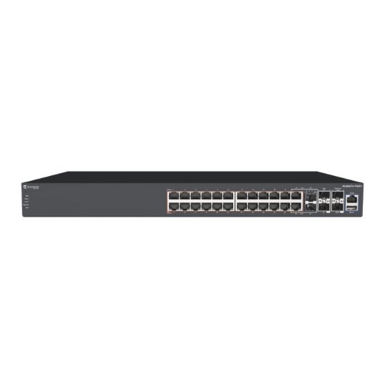
Enterprise Device Manager 4. work area—the main area on the right side of the window that displays the dialog boxes where you view or configure switch parameters Note: Depending on your hardware model, information displayed may appear different than the figure shown in this section. - Page 16 Fundamentals From the menu bar you can click the Device Physical View tab to open the Device Physical View any time during a session. Figure 2: Device Physical View Note: Depending on your hardware model, your switch may appear different than the figure shown in this section.
-
Page 17: Chapter 4: Connecting To The Switch
Chapter 4: Connecting to the switch Connecting a terminal to the switch This procedure describes the steps to connect a terminal to the console port on the switch. Before you begin To use the console port, you need the following equipment: •... -
Page 18: Configuring With Quick Start Using Cli
Connecting to the switch can be done using the available management interfaces. Use Ctrl+C to abort the configuration at any time. ######################################################################### Please provide the Quick Start VLAN <1-4094> [1]: Please provide the in-band IP Address[192.168.1.1]: Please provide the in-band sub-net mask[255.255.255.0]: Please provide the Default Gateway[0.0.0.0]: Please provide the Read-Only Community String[**********]: Please provide the Read-Write Community String[**********]:... - Page 19 Configuring with Quick Start using CLI The switch setup utility banner appears. 4. Enter VLAN ID for the Quick Start at the following prompt: Please provide the Quick Start VLAN <1–4094> [1]: 5. Enter the IP address at the following prompt: Please provide the in-band IP Address [192.0.2.1]: 6.
-
Page 20: Configuring Quick Start Using Edm
Connecting to the switch ############################################################################### Basic stack parameters have now been configured and saved. ############################################################################### Configuring Quick Start using EDM Perform this procedure to configure Quick Start to enter the setup mode through a single screen. Procedure 1. From the navigation tree, click Administration. 2. -
Page 21: Configuring The Terminal
Configuring the terminal Example Configuring the terminal You can configure the switch terminal settings to suit your preferences for the terminal speed and display. About this task Use the following procedure to configure terminal settings including the terminal connection speed, and terminal display width and length, in number of characters. -
Page 22: Variable Definitions
Connecting to the switch Example The following example shows the output from the show terminal command. Switch#show terminal Terminal speed: 9600 Terminal width: 79 Terminal length: 24 Variable definitions The following table describes the parameters for the terminal command. Variable Value speed {2400|4800|9600|19200|38400} Sets the transmit and receive baud rates for the... -
Page 23: Setting User Access Limits Using Cli
Setting user access limits using CLI Important: Whenever the switch is broadcasting BootP requests, the BootP process eventually times out if a reply is not received. When the process times out, the BootP request mode automatically changes to BootP or Default IP mode. To restart the BootP process, change the BootP request mode to any of the following modes: •... -
Page 24: Enabling And Disabling Passwords
Connecting to the switch Variable definitions The following table describes the parameters for the username command. Variable Definition <username> <password> Enter your user name for the first variable, and your password for the second variable. The default user name values are RO for read-only access and RW for read/write access. -
Page 25: Setting User Access Limits Using Enterprise Device Manager
Setting user access limits using Enterprise Device Manager Variable Definition security, see Configuring Security on Ethernet Routing Switch 3600 Series. serial | telnet Modify the password for serial console access or for Telnet access. none | local | radius | tacacs Indicates the password type being modified: •... -
Page 26: Configuring A Web And Telnet Password Using Edm
Connecting to the switch 8. In the Re-enter to verify dialog box for the Read-Write Switch Password, retype the character string. 9. On the toolbar, click Apply. Field descriptions Use the descriptions in the following table to configure the console switch password. Variable Definition Console Stack Password Type... -
Page 27: Customizing The Opening Banner
Customizing the opening banner Field descriptions Use the descriptions in the following table to configure the console switch password. Variable Definition Web/Telnet Stack Password Type Specify the type of password to use. Values include: • none—Disables the password • Local Password—Use the locally-defined password for serial console access •... -
Page 28: Displaying The Current Banner
Connecting to the switch configure terminal 2. At the command prompt, enter the following command: [no] banner [custom | static | disabled | <1–19> LINE ] Variable definitions The following table describes the parameters for the banner command. Variable Value static Displays the default agent-banner custom... -
Page 29: Configuring Simple Network Time Protocol
Configuring Simple Network Time Protocol Configuring Simple Network Time Protocol The Simple Network Time Protocol (SNTP) feature synchronizes the Universal Coordinated Time (UTC) to an accuracy within 1 second. This feature adheres to the IEEE RFC 2030 (MIB is the s5agent). -
Page 30: Configuring Daylight Savings Time
Connecting to the switch Variable definitions The following table describes the parameters for the clock time-zone command. Variable Value zone Specifies time zone acronym that can be displayed when showing system time; for example, EST for Eastern Standard Time. RANGE: Up to 4 characters hours Specify the hours difference from UTC. -
Page 31: Specifying Summer-Time Recurring Dates
Specifying summer-time recurring dates Variable Value RANGE: up to 4 characters date {<day> <month> <year> <hh:mm>} {<day> The first date specifies when summer time starts, <month> <year> <hh:mm>} and the second date specifies when summer time ends. • day — day of the month (RANGE: 1 to 31) •... -
Page 32: Displaying The Local Time Zone Settings
Connecting to the switch Variable definitions The following table describes the parameters for the summer-time recurring command. Variable Value <1–5> Specifies the week of the month. The first occurrence specifies when the recurring starts, and the second specifies when the recurring stops. <DAY>... -
Page 33: Displaying The Daylight Savings Time Settings
Displaying the daylight savings time settings Displaying the daylight savings time settings Display the daylight savings time settings. Procedure 1. Enter Global Configuration mode: enable configure terminal 2. At the command prompt, enter the following command: show clock summer-time Example The following figure provides a sample of the output of the show clock summer-time command. -
Page 34: Enabling Remote Access
Connecting to the switch Variable Value [no] Removes the specified static route. <dest-ip> Specifies the destination IP address for the route being added. DEFAULT: 0.0.0.0 is considered the default route. <mask> Specifies the destination subnet mask for the route being added. <next-hop>... -
Page 35: Using Telnet To Log On To The Device
Using telnet to log on to the device 3. To enable SSH remote access, enter the following command: 4. To enable SNMP remote access, enter the following command: snmp-server enable 5. To enable webpage remote access, enter the following command: web-server enable Example The following is an example of enabling telnet remote access:... -
Page 36: Accessing The Switch Through The Web Interface
Connecting to the switch Accessing the switch through the web interface You can use EDM to configure and maintain your switch through a web-based graphical user interface. You can monitor the switch through a web browser from anywhere on the network. By default, you can access the web interface using Hypertext Transfer Protocol Secure (HTTPS) only. -
Page 37: Variable Definitions
Saving the configuration Important: This procedure fails if the VLAN already exists. Procedure 1. Enter Global Configuration mode: enable configure terminal 2. At the command prompt, enter the following command: vlan create {<1–4094> | <vid_list>} [name <WORD>] [ type { port | protocol-ipv6Ether2 | voice-vlan}] | [voice-vlan] [msti <1–7>... -
Page 38: Configuring System Identification
Connecting to the switch Note: File Transfer Protocol (FTP) and TFTP support both IPv4 and IPv6 addresses, with no difference in functionality or configuration. Before you begin Enable the Trivial File Transfer Protocol (TFTP) on the switch. About this task Use this procedure to save the configuration. -
Page 39: Variable Definitions
Configuring system identification Note: Enter the community string twice. If you ran the install script to set up the configuration information, the read-write community name is already configured. 5. Configure the system name: snmp-server name <text> 6. Configure the system contact: snmp-server contact <text>... - Page 40 Connecting to the switch Table 3: snmp-server location command Variable Definition <text> Specify the SNMP system location value. Enter an alphanumeric string of up to 255 characters. Use the definitions in the following table to use the snmp-server host command. Table 4: snmp-server host command Variable Definition...
-
Page 41: Chapter 5: Configuring The Switch Using Cli
Chapter 5: Configuring the switch using Configuring the IP address Use this procedure to configure the IP address and subnet mask for the switch or stack. You can also use this procedure to select the boot mode for the next switch reboot. Important: When you change the IP address or subnet mask, you can lose connection to Telnet and the Web. -
Page 42: Configuring The Ip Address
Configuring the switch using CLI Variable Value switch | stack | unit <1–8> Specifies whether to set the IP address for the switch, the stack, or another unit in a stack. netmask Sets the IP subnet mask. default-gateway <A.B.C.D> Sets the IP address of the default gateway. Configuring the IP address Use this procedure to automatically obtain an in-band management IP address, subnet mask and default gateway on the switch or stack. -
Page 43: Clearing The Ip Address
Clearing the IP address Clearing the IP address Use this procedure to clear the existing IP address and subnet mask for the switch or stack or another unit of a stack. Important: When you change the IP address or subnet mask, you can lose connection to Telnet and the Web. -
Page 44: Changing Subnet Netmask Value
Configuring the switch using CLI show ip address Example The following figure displays a sample output for the show ip address command. Switch>show ip address Configured In Use Last BootP/DHCP ------------- ------------- --------------- Stack IP Address: 192.0.1.1 0.0.0.0 Switch IP Address: 192.0.1.2 192.0.1.2 0.0.0.0... -
Page 45: Configuring The Default Gateway
Configuring the default gateway Configuring the default gateway Use this procedure to configure the IP default gateway address for a switch, to change the IP default gateway address to the default address, or to clear the IP default gateway address. Important: When you change the IP gateway address, you can lose connection to Telnet and the Web. -
Page 46: Displaying Ip Configuration
Configuring the switch using CLI Displaying IP configuration This procedure is used to display the IP configuration, specifically BootP mode, switch or stack or unit address, subnet mask, and gateway address. These parameters are displayed for what is configured, what is in use, and the last BootP. Procedure 1. -
Page 47: Chapter 6: Verification
Chapter 6: Verification Verification Pinging an IP device You can ping a device to test the connection between a switch and another network device. After you ping a device, the switch sends an Internet Control Message Protocol (ICMP) packet to the target device. -
Page 48: Displaying The Agent And Diagnostic Software Load
Verification Variable Value {count <1–9999>} | continuous Sets the number of ICMP packets to be sent. The continuous mode sets the ping running until the user interrupts it by entering Ctrl-C. {timeout |-t} <1–120> Sets the timeout using either the timeout or -t parameter, followed by the number of seconds the switch must wait before timing out. -
Page 49: Displaying Rmon Alarms Using Cli
Verification Displaying RMON Alarms using CLI Displays information about RMON alarms. Procedure 1. Log on to CLI in Global Configuration command mode. 2. At the command prompt, enter the following command: show rmon alarm December 2017...
Need help?
Do you have a question about the ERS 3600 Series and is the answer not in the manual?
Questions and answers