
Related Manuals for EXTREME SWITCHING X8 Series


Summary of Contents for EXTREME SWITCHING X8 Series
- Page 1 ExtremeSwitching X8 Series Switches Hardware Installation Guide formerly BlackDiamond X Series 121158-01 Published December 2016...
- Page 2 Copyright © 2016 Extreme Networks All rights reserved. Legal Notice Extreme Networks, Inc. reserves the right to make changes in specifications and other information contained in this document and its website without prior notice. The reader should in all cases consult representatives of Extreme Networks to determine whether any such changes have been made.
-
Page 3: Table Of Contents
ExtremeSwitching X8 Series (Formerly BlackDiamond X Series) Installation Roadmap....8 ExtremeSwitching X8 Series (Formerly BlackDiamond X Series) Overview...........8 Features of the ExtremeSwitching X8 Series (Formerly BlackDiamond X Series) Chassis..... 9 Management Module Ports.............................. 11 Chapter 2: ExtremeSwitching X8 Series (Formerly BlackDiamond X Series) Modules and Fans............................. - Page 4 Table of Contents Applying Power and Accessing the Chassis for the First Time..............73 Chapter 7: Maintaining Your ExtremeSwitching X8 Series (formerly BlackDiamond X Series) Equipment........................76 Replacing a Power Supply............................. 76 Replacing a Fan Tray.................................79 Replacing a Management Module..........................81 Replacing a Fabric Module............................
-
Page 5: Preface
Italics are also used when referring to publication titles. Platform-Dependent Conventions ® Unless otherwise noted, all information applies to all platforms supported by ExtremeXOS software, which are the following: ExtremeSwitching X8 Series Switches Hardware Installation Guide for version 1.0... -
Page 6: Providing Feedback To Us
Networks employees, but is not intended to replace specific guidance from GTAC. • Support Portal — Manage cases, downloads, service contracts, product licensing, and training and certifications. Before contacting Extreme Networks for technical support, have the following information ready: ExtremeSwitching X8 Series Switches Hardware Installation Guide for version 1.0... -
Page 7: Related Publications
ExtremeXOS 16.2 User Guide • ExtremeXOS 16.2 Command Reference Guide • ExtremeSwitching and Summit Switches: Hardware Installation Guide for Switches Using ExtremeXOS 21.1 or Later • Environmental Guidelines for ExtremeSwitching Products ExtremeSwitching X8 Series Switches Hardware Installation Guide for version 1.0... -
Page 8: Chapter 1: Extremeswitching X8 Series (Formerly Blackdiamond X Series) Switches
The following sections provide an overview of the ExtremeSwitching X8 Series switch. ExtremeSwitching X8 Series (Formerly BlackDiamond X Series) Installation Roadmap After reading about the ExtremeSwitching X8 Series components, use the following roadmap to guide the initial installation of your chassis: Prepare your site. -
Page 9: Features Of The Extremeswitching X8 Series (Formerly Blackdiamond X Series) Chassis
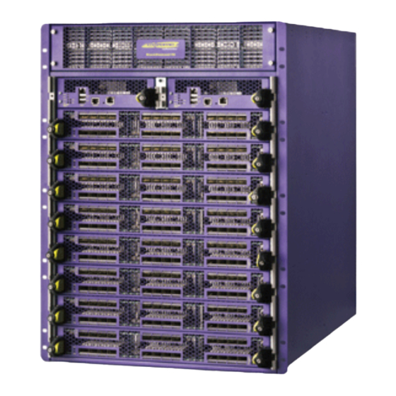
32 ports of 100GbE CFP2 per switch, 96 ports per rack Features of the ExtremeSwitching X8 Series (Formerly BlackDiamond X Series) Chassis The ExtremeSwitching X8 Series chassis has the following physical features: • Height of 14.5 RU, allowing three switches to be installed in a 7-foot tall, standard 19-inch rack •... - Page 10 ExtremeSwitching X8 Series (Formerly BlackDiamond X Series) Switches Figure 1: Front of the ExtremeSwitching X8 Series (Formerly BlackDiamond X Series) Chassis 1 = Power supply cover 3 = Management modules 2 = ESD jack 4 = I/O modules The front of the chassis provides access to: •...
-
Page 11: Management Module Ports
ExtremeSwitching X8 Series (Formerly BlackDiamond X Series) Switches Figure 2: Back of the ExtremeSwitching X8 Series (Formerly BlackDiamond X Series) Chassis 1 = Grounding point 3 = AC power input connectors 2 = ESD jack 4 = Fan trays The back of the chassis provides access to: •... - Page 12 Other devices, such as a USB external hard drive, will not be mounted. For more information, including a diagram showing the location of the management module ports, see Features of the Management Module on page 16. ExtremeSwitching X8 Series Switches Hardware Installation Guide for version 1.0...
-
Page 13: Chapter 2: Extremeswitching X8 Series (Formerly Blackdiamond X Series) Modules And Fans
Fabric Modules Fan Trays The following sections provide information on the ExtremeSwitching X8 Series management modules, I/O modules, switch fabric modules, and fans. Each module consists of a printed circuit board mounted on a metal panel. The module carrier also includes ejector/injector levers and captive retaining screws on the module front panel. - Page 14 ExtremeSwitching X8 Series (Formerly BlackDiamond X Series) Modules and Fans Table 3: Modules Available for the ExtremeSwitching X8 Series (Formerly BlackDiamond X Series) Switch Module Type Name Description Part No. (SKU) Management module BDX-MM1 Management Module 1 for 900848-10 ExtremeSwitching X8 Series chassis.
-
Page 15: Management Modules
ExtremeSwitching X8 Series (Formerly BlackDiamond X Series) Modules and Fans Table 3: Modules Available for the ExtremeSwitching X8 Series (Formerly BlackDiamond X Series) Switch (continued) Module Type Name Description Part No. (SKU) Up to eight modules in the chassis support up to 384 wirespeed 10GbE... - Page 16 ExtremeSwitching X8 Series (Formerly BlackDiamond X Series) Modules and Fans The following sections describe the functions and features of the ExtremeSwitching X8 Series (formerly BlackDiamond X Series) management modules: • Redundant Management Module Activity on page 16 • Features of the Management Module on page 16 •...
- Page 17 ExtremeSwitching X8 Series (Formerly BlackDiamond X Series) Modules and Fans • Console port : The RJ-45 serial console port is used to connect a terminal, allowing you to perform local management. • Auxiliary (AUX) port: For future development. Management modules have the following LEDs (see...
-
Page 18: I/O Modules
Packet activity is occurring. (on Management port) No packet activity is occurring. Auxiliary port For future development. (unlabeled) I/O Modules The following I/O modules are available for use with your ExtremeSwitching X8 Series (formerly BlackDiamond X Series) switch: • BDXA-G48T • BDXA-G48X •... - Page 19 ExtremeSwitching X8 Series modules. BDXA-G48T I/O Module The BDXA-G48T I/O module has 48 1Gb copper Ethernet ports. Note ExtremeSwitching X8 Series I/O modules are supplied with no pre-installed optical modules. Figure 4: BDXA-G48T I/O Module 1 = 1Gb Ethernet ports 2 = LEDs In the default configuration for the BDXA-G48T module, all ports: •...
- Page 20 ExtremeSwitching X8 Series (Formerly BlackDiamond X Series) Modules and Fans Figure 5: BDXA-G48X I/O Module 1 = 1GBASE-X SFP Ethernet ports 2 = LEDs In the default configuration for the BDXA-G48X module, all ports: • Are added to the default VLAN as untagged.
- Page 21 ExtremeSwitching X8 Series (Formerly BlackDiamond X Series) Modules and Fans BDXA-10G48X I/O Module The BDXA-10G48X I/O module supports 48 SFP+-based 10-gigabit Ethernet ports. Note ExtremeSwitching X8 Series I/O modules are supplied with no pre-installed optical modules. Figure 7: BDXA-10G48X I/O Module 1 = 10-Gigabit Ethernet ports 2 = LEDs In the default configuration for the BDXA-10G48X module, all ports: •...
- Page 22 24 ports; if all ports are operating in 10G mode, the module provides 96 ports. Note ExtremeSwitching X8 Series I/O modules are supplied with no pre-installed optical modules. When the ports are operating in 40-Gbps mode, the port numbers increment by 4. For example, the first four ports in the top row would be numbered (from left to right) 1, 5, 9, and 13.
- Page 23 TCAM entries. Note ExtremeSwitching X8 Series I/O modules are supplied with no pre-installed optical modules. When the ports are operating in 40-Gbps mode, the port numbers increment by 4. For example, the first four ports would be numbered (from left to right) 1, 5, 9, and 13. Other port numbers are displayed in ExtremeXOS as “not available.”...
- Page 24 Note To fully provision switching bandwidth for the BDXB-40G12X-XL module, the ExtremeSwitching X8 Series chassis must have at least three BDXA-FM10T fabric modules or three BDXA-FM20T fabric modules installed. A fourth fabric module of like type may be added for optional N+1 redundancy. The system can also be operated with a single fabric module of either type in an oversubscription mode.
- Page 25 10, 10-gigabit data channels. Note ExtremeSwitching X8 Series I/O modules are supplied with no pre-installed optical modules. When the ports are operating in 100-Gbps mode, the port numbers increment by 10. For example, the first four ports would be numbered (from left to right) 1, 11,21, and 31.
- Page 26 Note To fully provision switching bandwidth for the BDXB-100G4X-XL module, the ExtremeSwitching X8 Series chassis must have at least three BDXA-FM10T fabric modules or three BDXA-FM20T fabric modules installed. A fourth fabric module of like type may be added for optional N+1 redundancy. The system can also be operated with a single fabric module of either type in an oversubscription mode.
- Page 27 27. I/O Module LEDs LEDs on the front panel of the ExtremeSwitching X8 Series (formerly BlackDiamond X Series) I/O modules provide information about the operating status of the module and ports. Table 5: LEDs on the ExtremeSwitching X8 Series (Formerly BlackDiamond X Series)
-
Page 28: Fabric Modules
ExtremeSwitching X8 Series (Formerly BlackDiamond X Series) Modules and Fans Table 5: LEDs on the ExtremeSwitching X8 Series (Formerly BlackDiamond X Series) I/O Modules (continued) 40G Ports Port status Blue/steady Link is up and in 40G mode. Blue/blinking (4Hz blink 40G activity on port. -
Page 29: Fan Trays
The module is not present. Fan Trays At the back of the ExtremeSwitching X8 Series (formerly BlackDiamond X Series) chassis are five vertical fan trays, each holding six fans. Fan trays are hot-swappable. Two pairs of LEDs on each fan tray indicate operating status for the fabric module installed behind that fan tray. - Page 30 (starting from the left most side when looking at the rear of the chassis) are associated with fabric modules. Caution Never use the handles on the fan trays to lift the chassis. Figure 14: Fan Trays in the ExtremeSwitching X8 Series (Formerly BlackDiamond X Series) Chassis Table 7: LEDs for the Fan Trays Label/Function...
-
Page 31: Chapter 3: Power Supplies
Depending upon the load, with 110 VAC input the AC power supplies can operate in an N+N or N+1 configuration as well. Power supplies in the ExtremeSwitching X8 Series are fully fault tolerant and load-sharing in an N+1 configuration. After the system is properly configured, if one power supply fails, the others provide sufficient power to operate a fully loaded switch. -
Page 32: Ac Power Supply
Power Supplies The following topics describe how N+1 and N+N redundancy apply to the ExtremeSwitching X8 Series PSUs. Extreme Networks sales personnel can advise you on how much power to allocate for each module in your system and on the maximum power output each PSU can deliver. They can help you determine how many PSUs are needed to achieve the desired redundancy. - Page 33 3 = Inserter/extractor lever 2 = Release button Each ExtremeSwitching X8 Series AC power supply unit contains two cooling fans at the front of the unit. Airflow is from front to back. The AC power supply does not contain a field-replaceable fuse.
- Page 34 You can purchase AC power cords for use in the US and Canada from Extreme Networks or from your local supplier. An AC power cord for use with the ExtremeSwitching X8 Series AC power supply must meet the requirements listed in Power Cord Requirements on page 128.
-
Page 35: Chapter 4: Site Preparation
For power supply specifications, see Power Supplies for ExtremeSwitching X8 Series Switches on page 127. Requirements for the Operating Environment Verify that your site meets all environmental and safety requirements. ExtremeSwitching X8 Series Switches Hardware Installation Guide for version 1.0... - Page 36 445 12th Street SW electrical communication systems that originate in the Washington, DC 20554 United States according to the Communications Act of 1934. The FCC regulates all U.S. telephone and cable systems. ExtremeSwitching X8 Series Switches Hardware Installation Guide for version 1.0...
- Page 37 Maintain a storage temperature of -40° to 158°F (-40° to 70°C). Note As with all electrical equipment, Extreme Networks product lifetimes degrade with increased temperature. If possible, temperatures should be kept at approximately 78°F (25°C) or lower. ExtremeSwitching X8 Series Switches Hardware Installation Guide for version 1.0...
-
Page 38: Rack Specifications And Recommendations
297. In addition, verify that your rack meets the basic mechanical, space, and earthquake requirements that are described in this section. Mechanical Recommendations for the Rack Use equipment racks that meet the following mechanical recommendations: ExtremeSwitching X8 Series Switches Hardware Installation Guide for version 1.0... - Page 39 48 inches (122 cm) in front of the rack and 24 inches (61 cm) behind the rack. When using a relay (two-post) rack, provide a minimum of 24 inches (61 cm) of space behind the mounted equipment. Extra room on each side is optional. ExtremeSwitching X8 Series Switches Hardware Installation Guide for version 1.0...
-
Page 40: Cable Requirements
We recommend using the Building Industry Consulting Service International (BICSI) Registered Communications Distribution Designer (RCDD), which is globally recognized as a standard in site planning and cabling. For information, go to www.bicsi.org. ExtremeSwitching X8 Series Switches Hardware Installation Guide for version 1.0... - Page 41 Rating 1000BASE-SX 50/125 µm multimode fiber 500 meters (850 nm optical window) 50/125 µm multimode fiber 550 meters 62.5/125 µm multimode fiber 220 meters 62.5/125 µm multimode fiber 275 meters ExtremeSwitching X8 Series Switches Hardware Installation Guide for version 1.0...
- Page 42 10 km (1310 nm optical window) Proprietary to Extreme Networks. Connections between two Extreme Networks 1000BASE-LX interfaces that use 10/125 µm single-mode fiber can use a maximum distance of 10 km. ExtremeSwitching X8 Series Switches Hardware Installation Guide for version 1.0...
- Page 43 If you build your own cable, be sure that connectors are properly crimped. • When installing a patch panel using twisted pair wiring, untwist no more than 1/4 inch (6.4 mm) of the cable to avoid radio frequency (RF) interference. ExtremeSwitching X8 Series Switches Hardware Installation Guide for version 1.0...
- Page 44 Ethernet network environment, can cause excessive collisions, loss of link status, or other physical layer problems that can lead to poor performance or loss of communication. To prevent RF interference, avoid the following situations: ExtremeSwitching X8 Series Switches Hardware Installation Guide for version 1.0...
-
Page 45: Power Supply Requirements
For additional information on power supplies for ExtremeSwitching X8 Series (formerly BlackDiamond X Series) equipment, see the following topics: •... - Page 46 Débranchez tous les cordons d'alimentation avant l'entretien. AC Power Cord Requirements AC power input cords are not included with ExtremeSwitching X8 Series (formerly BlackDiamond X Series) power supplies. You can purchase AC power cords for use in the US and Canada from Extreme Networks or from your local supplier.
-
Page 47: Applicable Industry Standards
ANSI/TIA/EIA-568-A—discusses the six subsystems of a structured cabling system. • ANSI/TIA/EIA-569-A—discusses design considerations. • ANSI/TIA/EIA-606—discusses cabling system administration. • ANSI/TIA/EIA-607—discusses commercial building grounding and bonding requirements. You can access these standards at: www.ansi.org or www.tiaonline.org. ExtremeSwitching X8 Series Switches Hardware Installation Guide for version 1.0... -
Page 48: Chapter 5: Installing An Extremeswitching X8 Series (Formerly Blackdiamond X Series) Chassis
Save all packaging, bolts, and washers, as well as the box and pallet, for future use in the event that the chassis must be moved to another location or returned to Extreme Networks. Refer to the illustrations printed on the ExtremeSwitching X8 Series shipping container and unpack the chassis and accessories. - Page 49 Installing an ExtremeSwitching X8 Series (Formerly BlackDiamond X Series) Chassis Cut the straps around the box, as shown in the following figure. Figure 19: Unstrapping the Box ExtremeSwitching X8 Series Switches Hardware Installation Guide for version 1.0...
- Page 50 Installing an ExtremeSwitching X8 Series (Formerly BlackDiamond X Series) Chassis 2 Slide the box up and off the chassis and interior packing foam. the following figure. Figure 20: Removing the Box 3 Remove the inside corner braces. 4 Remove the support brackets and boxed accessories.
- Page 51 Installing an ExtremeSwitching X8 Series (Formerly BlackDiamond X Series) Chassis 6 Pull apart the keyed corner of the lower packing foam and remove the lower packing foam from around the chassis. the following figure. Figure 21: Removing the Accessories and Foam 7 On each side, remove the restraining bolts from the shipping brackets at the front and middle of the chassis.
- Page 52 Installing an ExtremeSwitching X8 Series (Formerly BlackDiamond X Series) Chassis 8 Remove all of the fan trays, one at a time. a Completely loosen the retaining screws at the top and bottom of the fan tray. b Holding both handles, pull straight outward on the fan tray to disconnect the internal connector.
-
Page 53: Pre-Installation Requirements
Installing an ExtremeSwitching X8 Series (Formerly BlackDiamond X Series) Chassis 11 Verify that the following items are included in the shipping carton: • ExtremeSwitching X8 Series chassis with installed front shipping cover and management module (MM) slot cover • Power cord retainer •... - Page 54 Installing an ExtremeSwitching X8 Series (Formerly BlackDiamond X Series) Chassis Before you install the chassis, verify that none of the modules or power supplies have been pre- installed. Because of the weight of the chassis, it should be empty when you install it.
- Page 55 Installing an ExtremeSwitching X8 Series (Formerly BlackDiamond X Series) Chassis 3 Using four rack mounting screws, attach the support bracket to the equipment rack immediately below the intended chassis location. the following figure. Figure 27: Attaching the Support Bracket Screws are not provided.
-
Page 56: Grounding The Chassis
Installing an ExtremeSwitching X8 Series (Formerly BlackDiamond X Series) Chassis 8 Secure the chassis to the equipment rack using six rack mounting screws. the following figure. Figure 28: Securing the Chassis to the Rack Screws are not provided. 9 Check to ensure screws are secure. -
Page 57: Installing Power Supplies
Installing an ExtremeSwitching X8 Series (Formerly BlackDiamond X Series) Chassis Figure 29: Grounding Pad on the Chassis 1 = Grounding pad 2 Strip 0.5 inch (1.2 cm) of insulation from the stranded copper wire cable. 3 Insert the stripped wire into the cable lug. - Page 58 Installing an ExtremeSwitching X8 Series (Formerly BlackDiamond X Series) Chassis Remove the power supply ventilation cover. a Loosen the retaining screws at the top corners of the cover panel. b Pull outward on the retaining screws to tilt the cover panel away from the front of the chassis.
- Page 59 Installing an ExtremeSwitching X8 Series (Formerly BlackDiamond X Series) Chassis 4 Slide the power supply into the chassis until the lever starts to engage. the following figure. Figure 32: Installing a Power Supply 5 Rotate the lever toward the front of the power supply to fully seat the power supply in the chassis.
-
Page 60: Connecting Power Cords
Align and tighten the retaining screws. Caution Do not operate the ExtremeSwitching X8 Series chassis without the power supply cover in place. This cover is required to maintain proper EMI levels for the switch. Figure 33: Installing the Power Supply Ventilation Cover... - Page 61 Installing an ExtremeSwitching X8 Series (Formerly BlackDiamond X Series) Chassis At the back of the chassis, connect an AC power cord to the power input socket that corresponds to each installed power supply. Power input sockets are numbered from 1A to 8B from left to right, as you face the chassis back See the following figure.
-
Page 62: Chapter 6: Installing Extremeswitching X8 Series (Formerly Blackdiamond X Series) Modules
The following sections describe how to install the modules and module blanks into the ExtremeSwitching X8 Series chassis. Note The ExtremeSwitching X8 Series chassis should already be installed before you install any modules into the chassis. See Installing an ExtremeSwitching X8 Series (Formerly BlackDiamond X Series) Chassis on page 48 for chassis installation procedures. -
Page 63: Required Tools
7 Use the lever to fully seat the module internal connectors, as shown in the following figure. Figure 36: Seating the Management Module ExtremeSwitching X8 Series Switches Hardware Installation Guide for version 1.0... -
Page 64: Installing A Management Module Blank
9 Install module blanks in all remaining unoccupied slots. Caution All unoccupied slots in an ExtremeSwitching X8 Series series switch must have module blanks correctly installed to ensure conformance to FCC requirements as well as to maintain adequate airflow through the switch. -
Page 65: Installing Fabric Modules
2 If it is not already connected, connect the metal end to the ESD jack at the right of the power input connectors. 3 Remove the fan tray from each location where you will install a fabric module. the following figure. Figure 38: Removing a Fan Tray ExtremeSwitching X8 Series Switches Hardware Installation Guide for version 1.0... - Page 66 Align the circuit board with the guides at the top and bottom of the chassis and slide the module into the chassis. the following figure. Figure 39: Installing a Fabric Module ExtremeSwitching X8 Series Switches Hardware Installation Guide for version 1.0...
- Page 67 Align and tighten the retaining screws to fasten the module in place. the following figure. Figure 40: Securing a Fabric Module 5 Repeat these steps to install additional fabric modules. ExtremeSwitching X8 Series Switches Hardware Installation Guide for version 1.0...
-
Page 68: Installing I/O Modules
To prevent ESD damage, hold the module by the metal rail and front panel only. Never touch the components on the PCB or the pins on any of the connectors. ExtremeSwitching X8 Series Switches Hardware Installation Guide for version 1.0... - Page 69 5 Carefully slide the module into the slot until the injector/ejector handles engage the edges of the chassis and begin to rotate toward the center of the module. 6 Push the handles toward each other to seat the module internal connectors. ExtremeSwitching X8 Series Switches Hardware Installation Guide for version 1.0...
-
Page 70: Installing I/O Module Blanks
After you have installed all of the I/O modules for your system configuration, you must install module blanks in all remaining unoccupied slots. Caution All unoccupied slots in an ExtremeSwitching X8 Series series switch must have module blanks correctly installed to ensure conformance to FCC requirements as well as to maintain adequate airflow through the switch. - Page 71 2 Carefully slide the I/O module blank into the slot until the injector/ejector handles engage the edges of the chassis and begin to rotate toward the center of the module. 3 Push the handles toward each other to seat the I/O module blank. ExtremeSwitching X8 Series Switches Hardware Installation Guide for version 1.0...
-
Page 72: Installing I/O Module Blanks (Without Thumb Levers)
After you have installed all the I/O modules for your system configuration, you must install module blanks in all remaining unoccupied slots. Caution All unoccupied slots in an ExtremeSwitching X8 Series series switch must have module blanks correctly installed to ensure conformance to FCC requirements as well as to maintain adequate airflow through the switch. -
Page 73: Applying Power And Accessing The Chassis For The First Time
Applying Power and Accessing the Chassis for the First Time After you have installed all of the modules and module blanks, apply power to the chassis. After the ExtremeSwitching X8 Series (formerly BlackDiamond X Series) equipment has completed all power on self-tests, it is operational. - Page 74 You can log in and configure an IP address for the default VLAN (named default). Note In ExtremeSwitching X8 Series switches, the management port on the management module is part of the management VLAN by default. Refer to Management Module Ports on page 11 for further details.
- Page 75 Your configuration changes are saved so that they will be in effect after the next system reboot. The configuration is saved to the configuration database of the management modules in the switch. 8 Enter logout. ExtremeSwitching X8 Series Switches Hardware Installation Guide for version 1.0...
-
Page 76: Chapter 7: Maintaining Your Extremeswitching X8 Series (Formerly Blackdiamond X Series) Equipment
Reseating a Management Module DIMM Packing the Chassis for Shipping The following sections contain maintenance procedures for the ExtremeSwitching X8 Series. Replacing a Power Supply To replace a power supply, you will need a #2 Phillips screwdriver to remove the power supply ventilation cover. - Page 77 Remove the power supply ventilation cover. Caution Do not operate the ExtremeSwitching X8 Series switch without the power supply ventilation cover in place. This cover is required to maintain conformance to FCC emissions regulatory requirements and proper EMI levels for the switch.
- Page 78 Maintaining Your ExtremeSwitching X8 Series (formerly BlackDiamond X Series) Equipment 4 Carefully slide the power supply out of the chassis and set it aside. the following figure. Figure 48: Removing a Power Supply 5 On the front of the replacement power supply, push the release button for the insertion/ejector lever.
-
Page 79: Replacing A Fan Tray
Maintaining Your ExtremeSwitching X8 Series (formerly BlackDiamond X Series) Equipment 8 Replace the power supply ventilation cover. a Set the lower edge of the cover in place so that the tabs on the edge fit into the matching slots in the chassis frame. - Page 80 Maintaining Your ExtremeSwitching X8 Series (formerly BlackDiamond X Series) Equipment 2 Holding both handles, pull straight outward on the fan tray to disconnect the internal connector. the following figure. Figure 51: Removing a Fan Tray 3 Set the fan tray aside in a safe place.
-
Page 81: Replacing A Management Module
Maintaining Your ExtremeSwitching X8 Series (formerly BlackDiamond X Series) Equipment 5 Align and tighten the retaining screws, as shown in the following figure. Figure 52: Installing a Fan Tray Replacing a Management Module You need the following tools and equipment to replace a management module: •... - Page 82 Maintaining Your ExtremeSwitching X8 Series (formerly BlackDiamond X Series) Equipment 4 On the injector/ejector lever, turn the captive screw counter-clockwise until the yellow band around the screw head of is completely visible. the following figure. Figure 53: Unlocking a Module 5 Squeeze the release latch on the injector/ejector handle and rotate the handle to the right (away from the module) to unseat the module from the internal connectors.
- Page 83 Maintaining Your ExtremeSwitching X8 Series (formerly BlackDiamond X Series) Equipment 6 Slide the module out of the chassis slot. the following figure. Figure 54: Removing a Management Module 7 Immediately place the module into an anti-static bag to protect it from potential ESD damage.
- Page 84 Maintaining Your ExtremeSwitching X8 Series (formerly BlackDiamond X Series) Equipment 4 Use the lever to fully seat the internal module connectors, as shown in the following figure. Figure 55: Installing a Management Module ExtremeSwitching X8 Series Switches Hardware Installation Guide for version 1.0...
-
Page 85: Replacing A Fabric Module
Maintaining Your ExtremeSwitching X8 Series (formerly BlackDiamond X Series) Equipment 5 Using a # 2 Phillips screwdriver, lock the handle into place. When the locking screw is fully tightened, the yellow band around the screw head is completely hidden. Refer to the following figure. - Page 86 Maintaining Your ExtremeSwitching X8 Series (formerly BlackDiamond X Series) Equipment • 5/16-inch flat-tip screwdriver for the retaining screws on the fabric module Caution If you are replacing a fabric module while the switch is operating, the new fabric module should be ready to insert. Insert the replacement and replace the fan tray within five minutes to insure that the switch does not overheat.
- Page 87 Maintaining Your ExtremeSwitching X8 Series (formerly BlackDiamond X Series) Equipment b Simultaneously rotate both levers toward the ends of the module to unseat the internal connectors. the following figure. Figure 58: Unseating a Fabric Module ExtremeSwitching X8 Series Switches Hardware Installation Guide for version 1.0...
- Page 88 Maintaining Your ExtremeSwitching X8 Series (formerly BlackDiamond X Series) Equipment c Carefully slide the module out of the switch chassis (see the following figure) and immediately place the module into an anti-static bag to protect it from potential ESD damage.
- Page 89 Maintaining Your ExtremeSwitching X8 Series (formerly BlackDiamond X Series) Equipment c Align the circuit board with the guides at the top and bottom of the chassis and slide the module into the chassis. the following figure. Figure 60: Installing a Fabric Module...
- Page 90 Maintaining Your ExtremeSwitching X8 Series (formerly BlackDiamond X Series) Equipment d When the levers start to engage, push them toward the module to seat the module in the chassis. e Align and tighten the retaining screws to fasten the module in place.
-
Page 91: Replacing An I/O Module
Maintaining Your ExtremeSwitching X8 Series (formerly BlackDiamond X Series) Equipment 7 Re-install the removed fan tray. a Set the fan tray into the chassis and push it firmly into place. b Align and tighten the retaining screws. the following figure. - Page 92 Maintaining Your ExtremeSwitching X8 Series (formerly BlackDiamond X Series) Equipment 4 On each injector/ejector lever, turn the captive screw counter-clockwise until the yellow band around the screw head of is completely visible. the following figure. Figure 63: Unlocking a Module 5 Squeeze the release latch on each injector/ejector handle and rotate both handles outward to disconnect the internal module connectors.
- Page 93 Maintaining Your ExtremeSwitching X8 Series (formerly BlackDiamond X Series) Equipment If you are not going to install a replacement module, install a blank front panel. For more information, Installing I/O Module Blanks on page 70. Installing a Replacement I/O Module You need the following tools and equipment to install an I/O module: •...
- Page 94 Maintaining Your ExtremeSwitching X8 Series (formerly BlackDiamond X Series) Equipment 6 Verify that the module injector/ejector handles are open. Keep the injector/ejector handles in the open position as you slide the module into the chassis slot. the following figure. Figure 65: Installing an I/O Module...
- Page 95 After you have installed all of the I/O modules for your system configuration, you must install module blanks in all remaining unoccupied slots. Caution All unoccupied slots in an ExtremeSwitching X8 Series series switch must have module blanks correctly installed to ensure conformance to FCC requirements as well as to maintain adequate airflow through the switch.
- Page 96 Maintaining Your ExtremeSwitching X8 Series (formerly BlackDiamond X Series) Equipment Verify that the I/O module blank injector/ejector handles are open. Keep the injector/ejector handles in the open position as you slide the I/O module blank into the unoccupied chassis slot.
- Page 97 After you have installed all the I/O modules for your system configuration, you must install module blanks in all remaining unoccupied slots. Caution All unoccupied slots in an ExtremeSwitching X8 Series series switch must have module blanks correctly installed to ensure conformance to FCC requirements as well as to maintain adequate airflow through the switch.
-
Page 98: Reseating A Management Module Dimm
Maintaining Your ExtremeSwitching X8 Series (formerly BlackDiamond X Series) Equipment 2 Align the module blank with the card guides for the open slot on the chassis. Figure 69: Installing a Module Blank without thumb levers 3 Use a #2 Phillips (cross-head) screwdriver to tighten the captive screws at each end of the module blank. - Page 99 Maintaining Your ExtremeSwitching X8 Series (formerly BlackDiamond X Series) Equipment 3 On the injector/ejector lever, turn the captive screw counter-clockwise until the yellow band around the screw head of is completely visible. the following figure. Figure 70: Unlocking a Module...
- Page 100 Maintaining Your ExtremeSwitching X8 Series (formerly BlackDiamond X Series) Equipment 4 Squeeze the release latch on the injector/ejector handle and rotate the handle to the right (away from the module) to unseat the module from the internal connectors. Caution To prevent ESD damage, hold the module by the metal rail and front panel only. Never touch the components on the PCB or the pins on any of the connectors.
- Page 101 Maintaining Your ExtremeSwitching X8 Series (formerly BlackDiamond X Series) Equipment 8 Remove any glue at the top of each latch with your fingers. the following figure. Figure 73: Glue on the top of the DIMM latch 1 = Glue 9 Unlock the DIMM, as shown in...
-
Page 102: Packing The Chassis For Shipping
Maintaining Your ExtremeSwitching X8 Series (formerly BlackDiamond X Series) Equipment 11 Repeat step on page 100 through step for the second DIMM. Packing the Chassis for Shipping To pack a chassis for shipping back to Extreme Networks or to another location, you need the following tools and materials: •... - Page 103 Maintaining Your ExtremeSwitching X8 Series (formerly BlackDiamond X Series) Equipment 2 Remove the fan trays, one at a time, as shown in the figure below. a Completely loosen the retaining screws at the top and bottom of the first fan tray.
- Page 104 Maintaining Your ExtremeSwitching X8 Series (formerly BlackDiamond X Series) Equipment 4 Slowly guide the chassis out of the equipment rack using the support bracket for support. 5 Attach the lifting handles to each side of the chassis. 6 Carefully lift the chassis off the support bracket and lower it onto the wood pallet the figure below.
- Page 105 Maintaining Your ExtremeSwitching X8 Series (formerly BlackDiamond X Series) Equipment 7 Re-install the removed fan trays as shown in the following figure: a Set each fan tray into the chassis and push it firmly into place. b Align and tighten the retaining screws.
- Page 106 Maintaining Your ExtremeSwitching X8 Series (formerly BlackDiamond X Series) Equipment At each corner, attach a restraining bolt to the shipping bracket, securing the chassis to the shipping pallet. the following figure. Figure 79: Recrating the ExtremeSwitching X8 Series (formerly BlackDiamond X Series) Chassis ExtremeSwitching X8 Series Switches Hardware Installation Guide for version 1.0...
- Page 107 Maintaining Your ExtremeSwitching X8 Series (formerly BlackDiamond X Series) Equipment 2 Put the lower foam cushion around the base of the chassis and set the upper foam cap on top of the chassis. the following figure. Figure 80: Placing the Foam Cushioning Around the Chassis...
- Page 108 Maintaining Your ExtremeSwitching X8 Series (formerly BlackDiamond X Series) Equipment 3 Set a corner brace at each corner of the chassis, and slide the shipping carton down over the chassis. the following figure. Figure 81: Placing the Shipping Carton over the Chassis...
- Page 109 Maintaining Your ExtremeSwitching X8 Series (formerly BlackDiamond X Series) Equipment 4 Secure the carton to the pallet using nylon strapping. the following figure. Figure 82: Shipping Carton with Nylon Straps ExtremeSwitching X8 Series Switches Hardware Installation Guide for version 1.0...
-
Page 110: Chapter 8: Safety Information
Consider the following items before installing equipment. • The system is designed to operate in a typical data center environment that is environmentally controlled. Choose a site that has the following characteristics: ExtremeSwitching X8 Series Switches Hardware Installation Guide for version 1.0... -
Page 111: Maintenance Safety
Install all cables in a manner that avoids strain. Use tie wraps or other strain relief devices. • Replace a power cord immediately if it shows any signs of damage. General Safety Precautions Follow safety guidelines to avoid injury. ExtremeSwitching X8 Series Switches Hardware Installation Guide for version 1.0... -
Page 112: Cable Routing For Lan Systems
Caution Failure to follow these requirements for cable routing conditions may expose the user to electrical shock and expose the unit to damage that can cause errors. ExtremeSwitching X8 Series Switches Hardware Installation Guide for version 1.0... -
Page 113: Installing Power Supply Units And Connecting Power
Do not connect the power supply to an electrical source when the power supply is not installed in the ExtremeSwitching X8 Series (formerly BlackDiamond X Series). Doing so would create a hazardous energy exposure and pose a potential shock and fire hazard. -
Page 114: Selecting Power Supply Cords
If a power source fails, it will affect only the power supplies to which it is connected. If all ExtremeSwitching X8 Series power supplies are connected to a single power source, the entire chassis is vulnerable to a power source failure. -
Page 115: Battery Warning - Taiwan
Although Extreme Networks does not block third-party optical modules, we cannot ensure that all third-party optical modules operate properly in all Extreme Networks switches. The customer assumes all risks associated with using third-party optical modules in Extreme Networks switches. ExtremeSwitching X8 Series Switches Hardware Installation Guide for version 1.0... -
Page 116: Sicherheitshinweise
Lassen Sie auf allen Seiten mindestens 3 Zoll Platz, um eine ausreichende Luftzirkulation zu gewährleisten. Die Lüftungsschlitze an der Vorder- oder Rückseite und an den Seiten dürfen nicht blockiert werden. Stellen Sie das System nicht in der Nähe von Wärmequellen auf. ExtremeSwitching X8 Series Switches Hardware Installation Guide for version 1.0... -
Page 117: Allgemeine Sicherheitshinweise
Störung das defekte Teil zur Reparatur oder zum Austausch an Extreme Networks ein, sofern ein Extreme Networks-Vertreter nicht etwas anderes angibt. • Um das System spannungslos zu machen, müssen Sie alle Netzkabel aus den Netzsteckdosen ziehen. Das Netzkabel ist der "Trennschalter" für die Netzspannungsquelle. ExtremeSwitching X8 Series Switches Hardware Installation Guide for version 1.0... -
Page 118: Kabelverlegung Für Lan-Systeme
Metallkontakt mit OSP-Verdrahtung. Diese Warnung gilt nicht für Ports vom Typ T1/E1, weil diese Ports über eine integrierte Isolierung und einen Schutz vor Spannungsspitzen verfügen, der den Anschluss an OSP- Verdrahtung gestattet. ExtremeSwitching X8 Series Switches Hardware Installation Guide for version 1.0... -
Page 119: Installation Der Netzteile Und Netzanschluss
Spannungsversorgung, um das System plötzlichen Spannungsschwankungen zu schützen. • Bei Systemen mit mehreren Netzteilen schließen Sie jedes Netzteil an einer anderen, unabhängigen Überstromschutzvorrichtung an, z. B. an einem Schütz. Bei Ausfall einer Spannungsquelle ist nur das ExtremeSwitching X8 Series Switches Hardware Installation Guide for version 1.0... -
Page 120: Auswahl Der Netzkabel
Transformator empfohlen, um die Spannung auf einen Wert unter < 240 VAC (Leiter- Leiter) herunterzutransformieren oder ein Anschluss an eine (P+N+Schutzerde) Spannungsverteilung, wo die Spannung 240 VAC nicht überschreitet. Alle Installationen müssen eine zuverlässige Erdung gemäß den nationalen Elektrovorschriften vorsehen. ExtremeSwitching X8 Series Switches Hardware Installation Guide for version 1.0... -
Page 121: Wechseln Und Entsorgen Der Batterie
Optische Geräte dürfen auf keine andere Weise als in diesem Dokument empfohlen verändert, modifiziert oder umgebaut werden. Konformität von GBIC, SFP (Mini-GBIC), QSFP+, XENPAK und XFP Steckbare optische Module von Extreme Networks und direkt angeschlossene Kabel erfüllen folgende gesetzliche Vorschriften. ExtremeSwitching X8 Series Switches Hardware Installation Guide for version 1.0... - Page 122 • Anwendung des CE-Zeichens gemäß der EMV-Richtlinie 2004/108/EEC und der Niederspannungsrichtlinie 2006/95/EC • UL und/oder CSA-geprüfte Komponente für Nordamerika • 47 CFR Teil 15, Klasse A bei Einbau in Extreme-Produkte ExtremeSwitching X8 Series Switches Hardware Installation Guide for version 1.0...
-
Page 123: Chapter 9: Technical Specifications
Power Supplies for ExtremeSwitching X8 Series Switches Power Cord Requirements Connector Pinouts Conformity Statements for EMC Class A This appendix includes specifications for ExtremeSwitching X8 Series (formerly BlackDiamond X Series) switches and related components. ExtremeSwitching X8 Series Switch ExtremeSwitching X8 Series Switch Technical Specifications... - Page 124 EN/ETSI 300 019-2-1 v2.1.2 - Class 1.2 Storage EN/ETSI 300 019-2-2 v2.3.1 - Class 2.3 Transportation EN/ETSI 300 019-2-3 v2.3.1 - Class 3.1e Operational EN/ETSI 300 753 v1.3.1 (2012-01) - Acoustic Noise ExtremeSwitching X8 Series Switches Hardware Installation Guide for version 1.0...
- Page 125 Low Speed: 7.5 B(A) in accordance with ISO 9296:1998 accordance with EN 300 753 v1.3.1 Medium Speed: 8.1 B(A) in accordance with ISO 9296:1998 (2011-11) High Speed: 9.7 B(A) in accordance with ISO 9296:1998 ExtremeSwitching X8 Series Switches Hardware Installation Guide for version 1.0...
-
Page 126: Modules For Extremeswitching X8 Series Switches
Length 18.46 inches by width 16.49 inches by height 2.29 inches (46.85 cm x 41.86 cm x 5.82 cm) Weight: 12.3 lb (4.9 kg) Packaged weight: 17.2 lb (7.3 kg) Power: 440W (Heat Dissipation 1,501 BTU) ExtremeSwitching X8 Series Switches Hardware Installation Guide for version 1.0... -
Page 127: Power Supplies For Extremeswitching X8 Series Switches
Power: 330 W (Heat Dissipation: 1126 BTU) Power Supplies for ExtremeSwitching X8 Series Switches Table 23: Specifications for the AC Power Supply (Model # 48011) Typical configuration 3 power supplies Full configuration 8 power supplies ExtremeSwitching X8 Series Switches Hardware Installation Guide for version 1.0... -
Page 128: Power Cord Requirements
Operational shock: 30 m/s (3 g) Power Cord Requirements There are specific requirements for power cords used with ExtremeSwitching X8 Series (formerly BlackDiamond X Series) AC power supplies. • The power supply cord must be agency-certified for country of use, and rated at 13 A by in-country regulatory authority. - Page 129 Technical Specifications Table 24: RJ-45 Console Port on ExtremeSwitching X8 Series Switch Function Pin Number Direction CTS (clear to send) DTR (data carrier detect) TXD (transmit data) GND (ground) — GND (ground) — RXD (receive data) DSR (data set ready)
-
Page 130: Conformity Statements For Emc Class A
Le présent appareil numérique n’émet pas de bruits radioélectriques dépassant les limites applicables aux appareils numériques de la class A prescrites dans le Règlement sur le brouillage radioélectrique édicté par le ministère des Communications du Canada. . ExtremeSwitching X8 Series Switches Hardware Installation Guide for version 1.0... - Page 131 Korean EMC Statement (KCC) Australia (RCM) This is a class A product. In a domestic environment this product may cause radio interference in which case the user may require to take adequate measures. ExtremeSwitching X8 Series Switches Hardware Installation Guide for version 1.0...
- Page 132 Veuillez communiquer avec l’assistance technique pour du soutien. Il y a risque d’explosion si la pile est remplacée par un type de pile incorrect. Éliminez les piles usées en conformité aux règlements locaux d'élimination des piles. ExtremeSwitching X8 Series Switches Hardware Installation Guide for version 1.0...
-
Page 133: Index
Building Industry Consulting Service International (BICSI) buildingstandards 47 default module configuration 18 bundling cable 43 design standards 47 documentation feedback 6 related 7 cables dual in-line memory module (DIMM) ExtremeSwitching X8 Series Switches Hardware Installation Guide for version 1.0... - Page 134 85 replacing 79 fan tray 79 features I/O module blanks 70, 72, 95, 97 BDXA-10G48T I/O module 20 I/O modules 68, 91, 93 BDXA-10G48X I/O module 21 management module blanks 62, 64, 85 BDXA-40G12X I/O module 21 ExtremeSwitching X8 Series Switches Hardware Installation Guide for version 1.0...
- Page 135 (RFI) N+N redundancy 32 and UTP cable 44 null-modem cable patch panel installation 43 pinouts 129 preventing 44 problems caused by 44 redundancy management modules 16 operating conditions 125 N+1 32 N+N 32 overview 31 replacing packing fabric modules 85 ExtremeSwitching X8 Series Switches Hardware Installation Guide for version 1.0...
- Page 136 83 ExtremeSwitching X8 Series Switches Hardware Installation Guide for version 1.0...
Need help?
Do you have a question about the X8 Series and is the answer not in the manual?
Questions and answers