Table of Contents
Advertisement
Quick Links
Advertisement
Table of Contents

Subscribe to Our Youtube Channel
Related Manuals for Lithium Grim Supreme Leader


Summary of Contents for Lithium Grim Supreme Leader
- Page 1 Supreme Leader Building instructions v1.0...
-
Page 2: Table Of Contents
Supreme Leader v1.0 Table of contents PCB layout ............................... 3 Components ............................4 Build sequence ............................5 Drilltemplate ............................6 Off board wiring ............................7 Potentiometers and switches ......................7 Modifications ............................8 Boost (foot)switch ..........................8 Troubleshooting ............................9 Schematic .............................. -
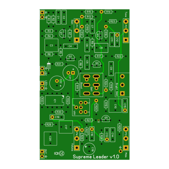
Page 3: Pcb Layout
Supreme Leader v1.0 PCB layout Dimensions: 83 mm x 49,55 mm 3.27 inch x 1.95 inch Manufacturers and product names are mentioned solely for circuit identification, and where applicable their trademarks are the property of their respective owners who are in no way associated or affiliated with the author. No cooperation or endorsement... -
Page 4: Components
Supreme Leader v1.0 Components Name Value Comment Name Value Comment 680p MLCC 1% metalfilm SMF/MKT/Wima 1% metalfilm SMF/MKT/Wima 1% metalfilm SMF/MKT/Wima 1% metalfilm SMF/MKT/Wima 1% metalfilm MLCC/Silver Mica 1% metalfilm 220p MLCC 1% metalfilm 220n SMF/MKT/Wima 1% metalfilm SMF/MKT/Wima 1% metalfilm... -
Page 5: Build Sequence
Supreme Leader v1.0 Build sequence Read the modifications section before you start building! Soldering this board can be very complicated for some people since the solder pads are very close together. Use a magnifying glass to make the job easier. -
Page 6: Drilltemplate
Supreme Leader v1.0 Drilltemplate Pots need 7mm holes, switches need 6mm holes. Mids Tone 59,4mm 13,95mm 13,95mm Bright 27mm 29,7mm Volume Gain Boost Manufacturers and product names are mentioned solely for circuit identification, and where applicable their trademarks are the property of their respective owners who are in no way associated or affiliated with the author. -
Page 7: Off Board Wiring
Supreme Leader v1.0 Off board wiring Potentiometers and switches In the pictures below you see the correct pin numbering of the pots (Alpha 16mm style). The rectangle pad marks pin 1. Before soldering the potentiometers and switches, mount them in the predrilled enclosure and then slide the PCB over them and solder them to the board. -
Page 8: Modifications
Supreme Leader v1.0 Modifications Boost (foot)switch On the original pedal SW1 only has 2 boost positions (on and off). On this PCB SW1 is by default a 3PDT (On-Off-On) switch soldered on the PCB and so giving you 3 options: High boost, no boost and a custom boost. -
Page 9: Troubleshooting
Supreme Leader v1.0 Troubleshooting All PCB’s have been 100% factory e-tested and out of every batch I receive I build an effect to double check, so there should not be a connection problem on the PCB itself. The board is not working (at all), what now? •... -
Page 10: Schematic
Supreme Leader v1.0 Schematic Manufacturers and product names are mentioned solely for circuit identification, and where applicable their trademarks are the property of their respective owners who are in no way associated or affiliated with the author. No cooperation or endorsement...
Need help?
Do you have a question about the Supreme Leader and is the answer not in the manual?
Questions and answers