Table of Contents
Advertisement
Quick Links
Advertisement
Table of Contents

Related Manuals for Lithium Grim Merlin


Summary of Contents for Lithium Grim Merlin
- Page 1 Merlin Building instructions V1.1...
-
Page 2: Table Of Contents
Merlin v1.1 Table of contents Components ............................3 PCB layout ............................... 3 Bill of Materials............................4 Building sequence ........................... 5 Modifications ............................6 Softclipping ............................6 Additional diodes..........................6 Diodes and Op amp ..........................6 Feedback loop ............................. 7 Lovepedal OD11 ................Fout! Bladwijzer niet gedefinieerd. -
Page 3: Components
Merlin v1.1 Components Name Value Comment Name Value Comment MKT/SMF 1% metalfilm 100p Silver mica 510k 1% metalfilm MKT/SMF 1% metalfilm MKT/SMF 1% metalfilm MKT/SMF 1% metalfilm MKT/SMF 1% metalfilm Electrolyte 16V+ 1% metalfilm Electrolyte 16V+ 1% metalfilm 150n MKT/SMF... -
Page 4: Bill Of Materials
Merlin v1.1 Bill of Materials Capacitors Value Amount Type Rating 1 MKT or SMF 16V or higher 1 MKT or SMF 16V or higher 1 MKT or SMF 16V or higher 1 MKT or SMF 16V or higher 150n 1 MKT or SMF... -
Page 5: Building Sequence
Merlin v1.1 Building sequence Soldering this board can be very complicated for some people since the solder pads are very close together. Use a magnifying glass to make the job easier. If you want to experiment with other diodes then you could socket them instead of soldering them to the board. You’ll need a 20 SIL, break off the sockets and solder them to the board. -
Page 6: Modifications
Merlin v1.1 Modifications Softclipping SW2 is a clipping mod for all versions. There is no specific order in which you need to solder it to the pads of SW2. Additional diodes You can have different choices for your diode switching. SW3 is used standard only for the Timmy™... -
Page 7: Feedback Loop
Merlin v1.1 As an alternative for using 2 DPDT switches, you can replace them by only one DP3T ON/OFF/ON switch to make use of 2 of the 3 switch options of the standard wiring: To SW3 To SW3 Feedback loop SW4 is an optional feedback loop mod using a DP3T ON/OFF/ON that can be added to all versions. - Page 8 Merlin v1.1 Creating other effect OD11 Name Value Comment Name Value Comment MKT/SMF 1% metalfilm 100p Silver mica 1% metalfilm MKT/SMF 1% metalfilm MKT/SMF 1% metalfilm MKT/SMF 1% metalfilm MKT/SMF 1% metalfilm Electrolyte 16V+ 1% metalfilm Electrolyte 16V+ 1% metalfilm...
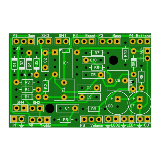
- Page 9 The diode configuration for the Zen Drive™ and OD11™ can be found below. A and B mart the spots on the Merlin PCB where you can connect an external board to is you are not mounting any diodes on the Merlin PCB and/or are not using the SW3 connection.
-
Page 10: Off Board Wiring
Merlin v1.1 Off board wiring The biggest challenge of this build is to get all the offboard wiring correct and fit it in a box. Take your time measuring and testing before you start fitting everything in the box. Wiring the pots P1-P6 is very simple. The rectangle pad marks pin 1 of a potentiometer. The images below show how you can recognize which pin is which on a potentiometer. - Page 11 Merlin v1.1 When building the Tim™ you will need to add the boost switch. In the original the boost potentiometer has a built in switch, but you can also use a footswitch with a LED to see if the boost is...
-
Page 12: Effects Loop
Merlin v1.1 Effects loop The Tim™ also uses an external effects loop consisting of a mono jack and a switching mono jack like this: The loop is connected as follows: Switch Sleeve Return Send Sleeve Manufacturer and product names are mentioned solely for circuit identification, and where applicable their trademarks are the property of their respective owners who are in no way associated or affiliated with the author. -
Page 13: Troubleshooting
Merlin v1.1 Troubleshooting All PCB’s have been 100% factory e-tested and out of every batch I receive I build an effect to double check, so there should not be a connection problem on the PCB itself. The board is not working (at all), what now? •... -
Page 14: Schematic
Merlin v1.1 Schematic Manufacturer and product names are mentioned solely for circuit identification, and where applicable their trademarks are the property of their respective owners who are in no way associated or affiliated with the author. No cooperation or endorsement...
Need help?
Do you have a question about the Merlin and is the answer not in the manual?
Questions and answers