Table of Contents
Advertisement
Quick Links
Advertisement
Table of Contents

Related Manuals for Lithium Grim Purple Vibe


Summary of Contents for Lithium Grim Purple Vibe
- Page 1 Purple Vibe Building instructions v1.0.1...
-
Page 2: Table Of Contents
Purple Vibe v1.0.1 Table of contents PCB layout ............................... 3 Components ............................4 Bill of Materials............................6 Options ..............................7 Build sequence ............................10 Off board wiring ............................ 11 Tone selector ............................. 11 Mode selector ........................... 12 Buffer switch ............................. 13 Pots .............................. -
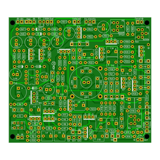
Page 3: Pcb Layout
Purple Vibe v1.0.1 PCB layout Dimensions: 97 mm x 85,5 mm 3,82 inch x 3,37 inch NB There is a small silkscreen error that does not affect the effect. On the PCB P5 is marked as Gain, but should be marked as Offset. Dito for P6 which is marked as Offset, but should be marked as Gain. -
Page 4: Components
Purple Vibe v1.0.1 Components All parts must be rated 25V+ Name Value Comment Name Value Comment 100n SMF J201 100n SMF 2N5089 2N5088 2N5088 2N5088 330p Ceramic 2N5088 2N5088 2N5088 2N5088 2N5088 C10a 2N5088 2N5088 2N5088 2N5087 2N5088 220n SMF... - Page 5 Purple Vibe v1.0.1 Name Value Comment Name Value Comment 100k 100k 100k 100k 220k 220k 220k 100k Lower up to 22k if needed 100k 100k 100k DPDT Buffer/Vintage LM7815 not LM78L15 100k 18v Lightbulb alternative 12v Manufacturers and product names are mentioned solely for circuit identification, and where applicable their trademarks are the property of their respective owners who are in no way associated or affiliated with the author.
-
Page 6: Bill Of Materials
Purple Vibe v1.0.1 Bill of Materials Resistors Semiconductors Amount Part Type Amount Part Type 1N4001 1N5817 1N914 Rate indicator/Status LED Bicolor common cathode LT1054 J201 2N5087 2N5088 2N5089 LM7815 100k Other 220k Amount Part Type 4P3T Mode and Tone switch... -
Page 7: Options
Purple Vibe v1.0.1 Options Before you start, you must decide which options you want to incorporate in the build. The original Univibe™ only has a Mode selector (Chorus/Vibrato). The Neovibe™ (GeoFX) was one of the first reconstructions of the original and followed by the Harbinger One™ (Madbean) which added an input buffer and charge pump. - Page 8 Purple Vibe v1.0.1 3. Tone selection If you want to leave out the tone selection and want to use only the original cap values in the phase stages then you will need to do the following: DO NOT SOLDER: C10a,C15a,C15b,C18a,C18b, C21a and Switch 3 (4P3T rotary) EXTRA JUMPERS: Connect SA to SA1, SB to SB1, SC to SC1, SD to SD1 4.
- Page 9 Purple Vibe v1.0.1 7. Power supply The PCB is designed to use a regular 9V adapter and raise the voltage to 18V with a built in charge pump. I do not advise the use of a battery in this build so I left it out in the descriptions! But feel free to have a different opinion and incorporate it anyway.
-
Page 10: Build Sequence
Purple Vibe v1.0.1 Build sequence Soldering this board can be very complicated for some people since the solder pads are very close together. Use a magnifying glass to make the job easier. The trick to soldering a PCB is to work from small to big components. -
Page 11: Off Board Wiring
Purple Vibe v1.0.1 Off board wiring Tone selector This build is a beast to wire, so we’ll do it in steps. We’ll start by soldering the most difficult part, the 4P3T Tone selector and after that the Mode selector. For those who have never worked with a 4P3T rotary switch, pay special attention. -
Page 12: Mode Selector
Purple Vibe v1.0.1 Mode selector If you decided not to use the Tremolo mode then you will not need the 4P3T but a SPDT (or DPDT if you want a LED indicator). Take a good look at the diagram and wire accordingly:... -
Page 13: Buffer Switch
Purple Vibe v1.0.1 Buffer switch SW1 marks the input buffer switch pads (see bottom left of the PCB image on the previous page). Notice it is in the same shape as a DPDT switch so it should be easy to solder the wires to the switch. -
Page 14: Footswitches
Purple Vibe v1.0.1 Footswitches The wiring of the footswitch and LED’s are the last steps. First of wired as true bypass with lamp cancellation. If you do not want to cancel the lamp then leave out the grey wire from the footswitch... - Page 15 Purple Vibe v1.0.1 As mentioned in the beginning, the original unit did not have true bypass, only lamp cancellation. You can wire it like that with this PCB, although I would not recommend it. Since only the lamp is turned off, all additional noise the unit generates will be audible and in your signal path.
-
Page 16: Setup
Purple Vibe v1.0.1 Setup You must first set the trim pots before you connect the DC jack. Start with these settings: • P1 (mix) at 12 o’clock • P5 (gain) at 12 o’clock • P6 (offset)all the way to the right Now, connect the DC and start turning up P5 until the lamp is bright enough. -
Page 17: Troubleshooting
Purple Vibe v1.0.1 Troubleshooting All PCB’s have been 100% factory e-tested and out of every batch I receive I build an effect to double check, so there should not be a connection problem on the PCB itself. The board is not working (at all), what now? •... -
Page 18: Schematic
Purple Vibe v1.0.1 Schematic Manufacturers and product names are mentioned solely for circuit identification, and where applicable their trademarks are the property of their respective owners who are in no way associated or affiliated with the author. No cooperation or endorsement...
Need help?
Do you have a question about the Purple Vibe and is the answer not in the manual?
Questions and answers