Advertisement
T echnical
Manual
Table of Contents
Specification...................................... 1
Parts List ........................................... 2~4
Case Outlines.................................... 4~5
Safety Caution................................... 5
PCB Assembly .................................. 6~8
Schematic Diagram .......................... 9~12
Specification
Total Harmonic Distortion
(20 Hz - 20 kHz 8 ohms)
Intermodulation Distortion
(60 Hz : 7 kHz 4 : 1)
Input Sensitivity / Impedance
Phono - MC
Phono - MM
Line Level
Phono Overload (MC/MM)
Output Level / Impedance
Frequency Response
Phono Input
Iine Level Input
Signal to Noise Ratio (IHF "A" weighted)
Phono - MC / MM
Line Level
Power Requirements
USA Version
European Version
Power Consumption
Dimensions (W x H x D)
Weight (net)
SHINSEN-BLD. 4F 10-10 SHINSEN-CHO, SHIBUYA-KU,
TOKYO 150-0045, JAPAN
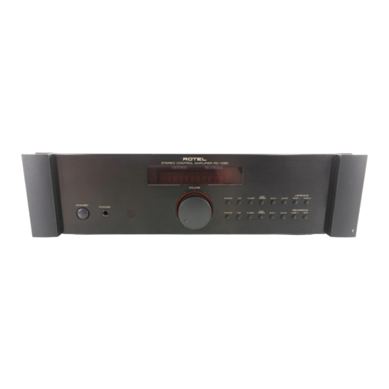
STEREO CONTROL AMPLIFIER
RC-1090
<0.004 %
<0.004 % at 1V output
0.25 mV / 100 ohms
2.5 mV / 47 kohms
150 mV / 18 kohms
16 mV / 160 mV
1 V / 100 ohms
20 Hz - 20 kHz, ± 0.2 dB
4 Hz - 100 kHz, ± 0.5 dB
70 dB / 75 dB
100 dB
115 volts, 60 Hz
230 volts, 50 Hz
13 Watts
430 x 125 x 345 mm
16
x 4
x 13
15/16
15/16
19/32"
7.8 kg/17.2 lb.
Serial. NO.
Beginning
Y-340A-01015C/S-S
Advertisement
Table of Contents

Related Manuals for Rotel RC-1090


Summary of Contents for Rotel RC-1090
-
Page 1: Table Of Contents
T echnical STEREO CONTROL AMPLIFIER RC-1090 Manual Table of Contents Specification........1 Parts List ........... 2~4 Case Outlines........4~5 Safety Caution........5 PCB Assembly ........6~8 Schematic Diagram ......9~12 Specification Total Harmonic Distortion <0.004 % (20 Hz - 20 kHz 8 ohms) Intermodulation Distortion <0.004 % at 1V output... -
Page 2: Parts List
Parts List-1 SYMBOL PARTS NO. DESCRIPTION SYMBOL PARTS NO. DESCRIPTION X-1299-01 PCB ASSEMBLY C401.402 044 TFKP2-2A101H CAPACITOR FILM 100V100PF Q513-516 033 TC2362-FG TRANSISTOR(2SC2362K-FG) C403.404 044 FSC160V331H CAPACITOR STYROL 160V330PF Q517.518 033 C2911-ST TRANSISTOR(2SC2911-ST) C405.406 044 FSC160V101H CAPACITOR STYROL 160V100PF Q519.520 033 A1209-ST TRANSISTOR(2SA1209-ST) C407.408... - Page 3 Parts List-2 SYMBOL PARTS NO. DESCRIPTION SYMBOL PARTS NO. DESCRIPTION 019 TO-126 INSULATION SHEET R930 053 CR16-103J-A RESISTOR CARBON 10K 069 C-3417A FUSE CLIP S901 061 4TR-2947 PUSH SWITCH(STANDBY) 069 C-4372A01 ※ AC OUTLET for STD X-1299-03 PCB ASSEMBLY C517.518 041 25BGF47M CAPACITOR ELEC.25V47UF X-1299-02 PCB ASSEMBLY...
-
Page 4: Case Outlines
Parts List-3 SYMBOL PARTS NO. DESCRIPTION SYMBOL PARTS NO. DESCRIPTION OTHERS R791 054 SE8104J THICK FILM RS NETWORK 100K 011 FP-533 SUB PANEL ASSY R792 054 SE7104J THICK FILM RS NETWORK 100K 011 TH3-01A00 H/S PANEL R793 054 SE8104J THICK FILM RS NETWORK 100K 012 C-4711A01 KNOB ASSY 43F S701-708... -
Page 5: Safety Caution
PCB Assembly AD 711J N AD 712J N LC4966 H IN23 2CP NE 5534 AN TC 74H C59 5AP NJ M 4556 AD TL07 1 CP T C91 63AN CX P82 832 Safety Caution Cautions during Inspection and Repair 1. Keep in mind the safety warnings The safety instructions are shown as the labels or printings on the exterior, the inside chassis or the parts, etc. - Page 6 PCB Assembly...
-
Page 7: Schematic Diagram
Schematic Diagram... - Page 8 Schematic Diagram...
Need help?
Do you have a question about the RC-1090 and is the answer not in the manual?
Questions and answers