Advertisement
Quick Links
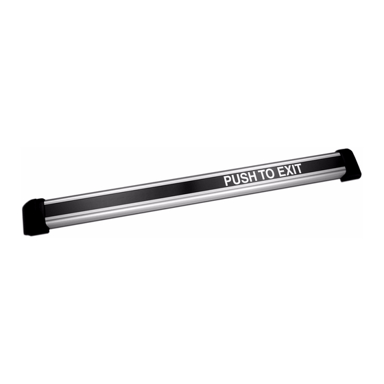
SERIES DSB DUAL SENSE BAR
INSTALLATION and OPERATION
Securitron Magnalock Corp.
Tel 800.624.5625
© Copyright, 2011, all rights reserved
INSTRUCTIONS
ASSA ABLOY, the global leader in
door opening solutions
www.securitron.com
techsupport@securitron.com
PN# 500-22700
Rev. F, 03/11
Advertisement

Related Manuals for Assa Abloy Securitron DSB Series


Summary of Contents for Assa Abloy Securitron DSB Series
- Page 1 ASSA ABLOY, the global leader in door opening solutions SERIES DSB DUAL SENSE BAR INSTALLATION and OPERATION INSTRUCTIONS Securitron Magnalock Corp. www.securitron.com Tel 800.624.5625 techsupport@securitron.com © Copyright, 2011, all rights reserved PN# 500-22700 Rev. F, 03/11...
-
Page 2: Specifications
Securitron Magnalock Corp. www.securitron.com ASSA ABLOY, the global leader Tel 800.624.5625 techsupport@securitron.com in door opening solutions SECURITRON SERIES DSB DUAL SENSE BAR INSTALLATION AND OPERATION INSTRUCTIONS 1. INTRODUCTION The Securitron Dual Sense Bar (Model DSB) is an exit device intended for use on magnetically locked, non-fire rated doors only. - Page 3 Fasteners for metal doors (aluminum frame and hollow steel) are included. For through door mounting please call Securitron for a no-charge DSB-TDM kit. Note that US standard or metric fasteners are supplied depending on the version of the bar which was ordered. (The metric version part number for a DSB series bar will include the suffix “M”).
- Page 4 The bar is level. The bar is centered on the door (left to right) between the door frame stops. By using the assembled bar as a template, the correct separation between the mounting holes will automatically be maintained. After marking the hole locations, verify that the centers of the holes are at the required distance as shown in Figure 4.
- Page 5 6.2. HOLLOW METAL DOOR PREPARATION The bar should be mounted to the door using the blind nuts and screws provided as shown in Figure 6. Use the following step-by-step instructions and Figure 5 for the installation of the blind nuts: a.
- Page 6 6.4. BOLT THROUGH DOOR PREPARATION: For through-bolt mounting on various door types a DSB-TDM kit will be required (see Figure 7). This product accessory is furnished separately and can be ordered from the factory at no charge. This configuration may be used on solid wood doors, hollow or solid metal doors, or chalk filled *fire doors.
- Page 7 e. Insert each end of the (spiral) conduit into the recess of each of the cord caps and mount each cap to the door and frame using a Phillips screwdriver and two (2) #6 X 3/4” long pan head screws provided. Figure 8 IS SUGGESTED THAT WIRE...
- Page 8 i. Mark the bar to indicate the desired cut. Note: For a DSB with the illuminated sign option, the bar should always be cut on the end that houses the main (TS) PC board. This will be the end opposite the LED light strip. j.
- Page 9 8. ELECTRICAL CONNECTIONS AND WIRING 8.1. DSB WIRING The DSB is supplied with either a 16-foot [4.88 meter] long cable with traditional wire leads or an ElectroLynx wiring harness. Either of these wiring devices may be used to connect power to the main PC board of the DSB.
- Page 10 Figure 12 – Double Door (No Access Control Unit) Fail secure electric locks are normally not permitted for use with the DSB on required exit applications. Normally open contacts, however, are available for special signaling applications and for integration with the Request to Exit (REX) function of an access control installation. The following wiring diagrams (Figures 13 and 14) show typical connections of the dual sense bar, power supply and a fail safe lock in use on single and double door exits with an access control unit.
- Page 11 Figure 15 shows the installation of an MOV in parallel with the magnetic lock. An MOV is provided with each DSB. It is a black (or blue) disk-like component with two bare wires for connection. The MOV acts to suppress the inductive kickback by a lock, which if left unsuppressed will greatly shorten the life of the relay contacts.
- Page 12 Figure 16 This product was designed for use with Securitron Magnalocks. The Magnalock secures the door with magnetic force only and therefore has no possibility of jamming and thereby denying egress. The Magnalock also has internal electronics which allow it to release very rapidly. When used with the DSB, which is also a fast device, exit is immediate and the impression a person exiting gets is that the door is not locked at all.
- Page 13 Make sure that the bar is installed with the plastic washers under the head of the mounting screws. Make sure there are no foreign objects or material creating a conductive path from the bar to the door (e.g. metal blinds, etc.). ...
- Page 14 Spring Plunger Housing Screws PC Board - Loosen and leave in place through holes! End Mount Base Riser 4. Using a #1 Phillips screwdriver, back out the two (2) screws to release the base riser from the rest of the end mount assembly. NOTE: These screws should remain in place (in the holes of the spring plunger housing and end mount) –...
- Page 15 3 INSTALL POWER CORD AND FLEXIBLE DOOR CORD SHIELD Connector Power Cord Door Cord Insert Flexible Door Cord Shield 1. Unroll the DSB power cord and feed the 3. Insert the door cord insert into the end of the non-connector end down through the wire flexible door cord shield.
- Page 16 4 REASSEMBLE END MOUNT ASSEMBLY IF the PC board and plunger slide out of the end mount: Screws Screws Connector Spring Plunger End Mount Housing Plunger Spring 1. Insert connector of power cord through NOTE: The PC Board is glued to the plunger wire feed thru hole in the end mount and housing which is a spring loaded assembly.
- Page 17 MAGNACARE LIFETIME REPLACEMENT WARRANTY For warranty information visit: www.securitron.com/en/site/securitron/About/MagnaCare-Warranty PN# 500-22700 Page 16 Rev. F, 03/11...
Need help?
Do you have a question about the Securitron DSB Series and is the answer not in the manual?
Questions and answers