Table of Contents
Advertisement
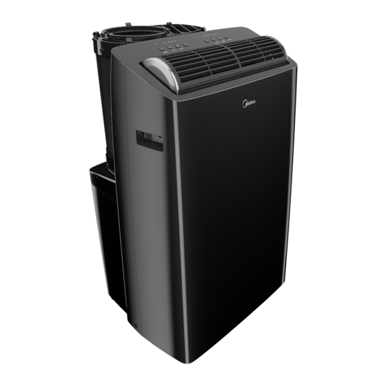
Window Air Conditioner
MAP
Capacity: 12000 ~ 14000BTU/h
Warning notices: Before using
this product, please read this
manual carefully and keep it for
future reference. For additional
support, please call customer
service at 1-866-646-4332.
The design and specifications are
subject to change without prior
notice for product improvement.
Consult with your dealer or
the manufacturer for details.
version E - 09 - 2020 (PREVIEW08)
version B - 02 - 2020
USER MANUAL
en
MAP12S1TBL
MAP14S1TBL
MAP14HS1TBL
Customer service:
1(866)-646-4332
Midea.com
Advertisement
Table of Contents

Related Manuals for Midea MAP


Summary of Contents for Midea MAP
- Page 1 The design and specifications are MAP12S1TBL subject to change without prior MAP14S1TBL notice for product improvement. MAP14HS1TBL Consult with your dealer or Customer service: the manufacturer for details. 1(866)-646-4332 Midea.com version E - 09 - 2020 (PREVIEW08) version B - 02 - 2020...
- Page 2 User Manual Safety Precautions ........................3 Operating Instructions ......................8 Installation Instructions ......................13 Care and Cleaning ........................19 Troubleshooting Tips ......................20 Remote Control and App Instructions ................21 Read This Manual Inside you’ll find many helpful hints on how to use and maintain your air conditioner properly. Just a little preventive care on your part can save you a great deal of time and money over the life of your air conditioner.
- Page 3 SAFETY PRECAUTIONS To prevent injury to the user or other people and property damage, the instructions shown here must be followed. Incorrect operation due to ignoring of instructions may cause harm or damage. The level of risk is shown by the following indications. This symbol indicates a hazardous situation which, if not avoided, WARNING could result in death or serious injury.
- Page 4 WARNING • Do not damage or use an alternate power cord. It may cause fi re and electric shock. If the power cord is damaged, it must be replaced by the manufacturer in order to avoid a hazard. • Do not direct airfl ow straight into persons to avoid possible health hazard. •...
- Page 5 CAUTION • Hold the plug by the head of the power plug when taking it out. Otherwise, it may cause electric shock and damage. • Ensure that the installation is properly secured to prevent the product from potentially falling. • Do not place heavy objects on the power cord and ensure that the cord is not compressed.
- Page 6 EXPLANATION OF SYMBOLS DISPLAYED ON THE UNIT This symbol shows that this appliance used a fl ammable refrigerant. WARNING If the refrigerant is leaked and exposed to an external ignition source, there is a risk of fi re. CAUTION This symbol shows that the operation manual should be read carefully. This symbol shows that a service personnel should be handling this CAUTION equipment with reference to the installation manual.
- Page 7 Operation of Current Device The power supply cord contains a current measuring device that detects damage to the Plug in & press RESET power cord. Test your power supply cord as follows: RESET 1. Plug in the air conditioner. 2. The power supply cord will have TWO TEST buttons on the plug head.
- Page 8 OPERATING INSTRUCTIONS Preparation Control panel Outlet louver (automatic swing) Upper air filter (behind the grille) Handle (both sides) Inlet and outlet air hose Air inlet Panel Drain outlet Drain outlet (heat pump models only) Power cord outlet Caster Bottom tray Power plug storage drain outlet Unit Operating Temperature Range:...
- Page 9 Control Panel Features Swing (Connect) Wireless Indicator LED Display Power Button Button Timer Mode Up ( ) and Down ( ) Sleep Button Buttons Button Button Button Swing Button , the constant fan light will go out, indicating that the fan will stop Used to initiate the Auto Swing feature.
- Page 10 ows Error codes and protection code: P1 - Bottom tray is full - Connect the drain hose The unit may stop operation or continue to run safely. and drain the collected water away. If If the error codes appear, wait for about 10 minutes. protection code repeats, call for service.
- Page 11 SLEEP operation NOTICE Pressing this button will increase (during cooling operation) or decrease (during heating operation, applicable models) 2°F/1°C after The SLEEP operation feature is 30 minutes. The temperature will again increase (cooling) or decrease unavailable in FAN or DRY mode. (heating) by another 2°F/1°C after an additional 30 minutes.
- Page 12 WATER DRAINAGE (Under heat mode) • Remove the middle drain plug from the back of the unit and install the drain connector (5/8” universal female adapter) with a 3/4“ hose (not included). For models without the drain connector, attach the drain hose to the connector. Place the end of the hose in the drain area you’re using.
- Page 13 INSTALLATION INSTRUCTIONS Choosing the Right Location Your installation location should meet the following requirements: • Make sure that you install your unit on an even surface to minimize noise and vibration. • The unit must be installed near a grounded plug, and the Collection Tray Drain (found on the back of the unit) must be accessible.
- Page 14 Tools Needed • Phillips screwdriver • Tape measure or ruler • Knife or scissors • Saw (optional, to shorten window adaptor for narrow windows). Accessories ts windows 19.05’’-63.86’’ (48.4-162.2 cm). Part Description Quantity Air exhaust adapter 1 pc Bolt 8 pc Window Sliders 5 pc Window Kit Brace...
- Page 15 Window Installation Kit 1: For Hung Window types only Air Exhaust Insert the Air Exhaust Adapter into the Adapter exhaust of the hose (the circle opening). Rotate the adapter clockwise until the locking Exhaust tabs click and no longer rotates. Hose Skip this step if installing into a horizontal sliding window.
- Page 16 Sliding 3: Assembling the Sliding Window Adapter (Only needed Window for Sliding Window applications). Adapter Align both halves of the sliding window adapter and connect them. Then, attach the air divider to the newly formed window adapter on the outdoor side. The fully assembled adapter should look like the image at the left.
- Page 17 Cut the non-adhesive foam seal C strip to match the width Foam seal C (Non-adhesive type) of the window. Insert the seal between the glass and the window frame to prevent air and insects from getting into the room. If desired, install the security bracket with 2 screws as shown.
- Page 18 3. Cut the non-adhesive foam seal C strip to match the Foam seal C window height. Insert the foam seal between the glass and (Non-adhesive type) the window frame to prevent air and insects from getting into the room. 4. If desired, install the security bracket with 2 screws as shown. Security Bracket 2 Screws...
- Page 19 NOTICE To ensure proper function, DO NOT overextend or bend the hose. Make sure that there are no objects within 20in (~500mm) of the inlet and outlet hose. All illustrations in this manual are for explanation purposes only, your air conditioner may be slightly dierent than shown. User Manual Page 19...
- Page 20 CARE AND CLEANING Safety Precautions • Always unplug the unit before cleaning or servicing. • DO NOT use flammable liquids or chemicals to clean the unit. • DO NOT wash the unit under running water. Doing so causes electrical danger. •...
- Page 21 TROUBLESHOOTING TIPS Before calling service, review this list. It may save you time and expense. This list includes common occurences that are not the result of defective workmanship or materials of this appliances. Problem Solution Unit does not turn on Displays P1 Error Code and means the water collection tray is full.
- Page 22 REMOTE CONTROL AND APP INSTRUCTIONS Handling the Remote Control LOCATION OF THE REMOTE CONTROL Use the remote control within a distance of 26 ft. (8m) from the air conditioner, pointing it towards the unit. The unit will beep when it receives a signal. CAUTION •...
- Page 23 BATTERY DISPOSAL Ensure used batteries are disposed of properly. TIPS FOR USING REMOTE CONTROL • The remote control must be used within 26 feet / 8 meters of the unit. • The unit will beep when it receives a signal from the remote. Curtains, other materials and direct sunlight can interfere with the IR signal receiver.
- Page 24 Remote Screen Indicators Information is displayed when the remote control is powered on. The Comfort SENSE function enables the Fresh feature display (Not applicable) remote control to measure the temperature at its current location and send this signal to Sleep mode display the air conditioner every 3 minutes interval.
- Page 25 Setting the Timer TIMER ON/OFF - Set the amount of time after which the unit will automatically turn on/off. TIMER ON SETTING Press TIMER ON button Press up or down button for Point remote to unit and wait to initiate the ON time multiple times to set the desired 1sec, the TIMER ON will be sequence.
- Page 26 DECLARATION OF CONFORMITY We hereby declare that this AC is in compliance with the essential requirements and other relevant provisions of Directive 1999/5/EC. SPECIFICATION OF WIRELESS MODULE Model: US-OSK103 Dimensions: 41 x 24 x 5 (mm) Standard: IEEE 802.11 b/g/n Operation Temperature: 0°C ~ 45°C / 32°F ~ 113°F.
- Page 27 This equipment has been tested and found to comply with the limits for a Class B digital device, pursuant to part 15 of the FCC Rules. These limits are designed to provide reasonable protection against harmful interference in a residential installation. This equipment generates, uses and can radiate radio frequency energy and, if not installed and used in accordance with the instructions, may cause harmful interference to radio communications.
- Page 28 Operating Instructions. 2) Damages caused by services performed by persons other than authorized Midea costumer service; or external causes such as abuse, misuse, inadequate power supply or acts of God.
- Page 29 How to Stay Cool with a New Portable Air Conditioner Because of a new federal test procedure for Portable Air Conditioners, you may notice that the cooling capacity claims on portable air conditioner packaging are significantly lower than that of models produced prior to 2017. This is due to changes in the test procedure, not to the portable air conditioners themselves.
- Page 30 Important Safety Instructions of Power Supply Cord WARNING To reduce the risk of the fire, electric shock, or injury to persons, read the Important Safety Instructions of Power Supply Cord before operating this appliance. The power supply cord with this air conditioner contains a current NOTE detection device designed to reduce the risk of fire.
Need help?
Do you have a question about the MAP and is the answer not in the manual?
Questions and answers
Who services the Midea MAP14HS1TBL?
Service for the Midea MAP14HS1TBL is provided by Midea Consumer Services or an authorized Midea service provider. To obtain service, contact Midea Consumer Services at 1-866-646-4332.
This answer is automatically generated