Table of Contents
Advertisement
Quick Links
Advertisement
Chapters
Table of Contents

Subscribe to Our Youtube Channel
Related Manuals for THORLABS DC2100


Summary of Contents for THORLABS DC2100
- Page 1 Operation Manual Thorlabs Instrumentation High Power LED Driver DC2100 2009...
- Page 2 Version: Date: 08.09.2009 © 2009 Thorlabs...
-
Page 3: Table Of Contents
3.2.2.2 Installing VISA Runtime Engine 3.2.2.3 ..............................17 Installing the Remote Application 3.2.2.4 ..............................18 Driver Installation 3.2.3 Operating the DC2100 by the Remote Application ................................. 19 3.2.3.1 ..............................19 Connecting a Device 3.2.3.2 ..............................20 Constant Current Mode 3.2.3.3 .............................. -
Page 4: 7.6 List Of Acronyms
................................. 40 7.3.1 Common Data 7.3.2 Technical Data ................................. 40 7.4 Letter of Volatility ........................... 41 7.5 Thorlabs 'End of Life' Policy (WEEE) ........................... 42 ................................. 42 7.5.1 Waste Treatment on your own Responsibility 7.5.2 Ecological Background ................................. 42 7.6 List of Acronyms ........................... -
Page 5: Foreword
Thorlabs GmbH This part of the instruction manual contains every specific information on how to handle and use the DC2100 High Power LED Driver. WARNING This symbol in the manual explains dangers that might result in personal injury or death. -
Page 6: General Information
1 General Information General Information The LED driver DC2100 is designed for general purpose LED control. It is a high power LED driver, which can supply a high current of up to 2 A at a maximum forward voltage of 24V to a high-power LED. This LED driver can also be used to drive the LED microscope illumination source MxxxLx - series. - Page 7 Thorlabs GmbH is not responsible for any radio television interference caused by modifications of this equipment or the substitution or attachment of connecting cables and equipment other than those specified by Thorlabs GmbH. The correction of interference caused by such unauthorized modification, substitution or attachment will be the responsibility of the user.
-
Page 8: Ordering Codes And Accessories
1 General Information Ordering Codes and Accessories Ordering code Short description DC2100 DC2100 - High Power LED Driver M365L1 Mounted LED Source @ 365nm M385L1 Mounted LED Source @ 385nm M405L1 Mounted LED Source @ 405nm M660L1 Mounted LED Source @ 660nm... -
Page 9: Getting Started
1 General Information Getting Started This section is provided for those interested in getting the DC2100 up and running quickly. The more detailed description and advanced features are described in the following sections. Unpacking Inspect the packaging for damage. If the shipping container seems to be damaged, keep it until you have inspected the contents and you have inspected the DC2100 mechanically and electrically. -
Page 10: Figure 1 Connecting A Led To The Dc2100
5. After the device is powered up, the graphics display will show a 'Welcome' screen for a few seconds. 6. The DC2100 is immediately ready to use after turning on. The rated accuracy is reached, however, after a warming-up period of approximately 10 minutes. -
Page 11: Operating Elements
2 Getting Started Operating Elements 2.3.1 Operating Elements on the Front Panel ´ Figure 2 Display and Operating Elements on the Front Panel 2.3.2 Operating Elements on the Rear Panel Figure 3 Operating Elements on the Rear Panel DC2100... -
Page 12: Operating The Dc2100
2 Getting Started Operating the DC2100 The DC2100 can either be controlled via the front panel of the main unit (see chapter Operation and Settings) or by a remote application (see chapter Remote Application). Operation and Settings The following sub chapters contain the description about the operation of the DC2100. -
Page 13: Operation Modes
This can be done while the main menu is selected by pressing the LED button. The last selected operation mode will be saved. After switching on the DC2100 again this operation mode will be automatically the active mode. All settings are saved and validated after a shut off. -
Page 14: Pulse Width Modulation Mode
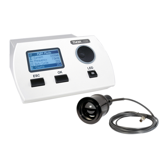
3 Operating the DC2100 3.1.2.2 Pulse Width Modulation Mode This mode can be used to apply a pulse width modulation to the LED with a defined frequency, amplitude, duty cycle and number of periods. Especially for spectral and power measurements this operation mode can be very useful. -
Page 15: External Control Mode
The 'External Control Mode' has no parameter settings. The LED can only be controlled via the BNC connector at the rear panel of the DC2100. The applied voltage corresponds to the LED current. 1V is equivalent to a LED current of 200mA. -
Page 16: Settings And Configuration
3 Operating the DC2100 Figure 13 External Control Mode The Modulation Frequency range is 0 to 100kHz and valid for sine wave modulation. 3.1.3 Settings and Configuration There are settings and system configurations, which can be accessed via the main menu. -
Page 17: Settings
LED Configuration The LEDs maximum current can be reconfigured for LEDs with an EEPROM. This value is valid until the DC2100 is restarted and can be changed in the 'User Limit Current' menu. This menu entry is hidden in normal operation mode. Go to the 'User Limit' screen described above. -
Page 18: About
DC2100 and the connected LED head if available. Figure 18 About Panel Remote Application The DC2100 remote software can be used to operate the DC2100 - High Power Driver via the PC. The device has to be connected to the PC by an USB cable. 3.2.1 Requirements... -
Page 19: Installing Visa Runtime Engine
3.2.2.3 Installing the Remote Application Select 'DC2100 - Application software' from the installation menu to start the installation wizard. If you are running Windows VISTA©® you might be prompted to change to the 'elevated mode', as shown in the following figure. Please ask your administrator for help when you do not have administrator privileges. -
Page 20: Driver Installation
Confirm with 'Next' when you selected the installation path of your choice. Follow the instruction of the installation wizard in order to install the remote software and drivers for the DC2100. During the installation process a separate installation wizard will start to register the device drivers on your system. -
Page 21: Operating The Dc2100 By The Remote Application
3. A message appears informing that the software has failed the Windows logo test. Click 'Continue Anyway'. 4. Finalize the installation by clicking 'Finish'. After this first installation the 'DC2100 - High Power LED Driver will be installed. Repeat step 1 to 4. 3.2.3... -
Page 22: Constant Current Mode
Figure 23 The Device Selection Dialog Select your DC2100 - High Power LED Driver by double-clicking or pressing the 'Accept' button. The device will be connected and the last active mode will be entered. The upload of the actual values on the system may take some seconds. -
Page 23: Pulse Width Modulation Mode
In this mode the LED can only be controlled via the BNC connector at the rear panel of the DC2100. The applied voltage corresponds to the LED current. 1V is equivalent to a LED current of 200mA. A maximum voltage of 10V can be applied, which will result in a current of 2A. -
Page 24: User Limit Current
3.2.3.5 User Limit Current The user can set an individual current limit. Some of the Thorlabs LED heads feature an EEPROM where the LEDs maximum current limit is stored. The user current limit has to be below or equal to this maximum current limit. - Page 25 3 Operating the DC2100 Figure 29 Device Information The following screen appears containing the serial number, device name, manufacturer, driver version and firmware revision. Figure 30 Device Information Dialog If a channel information was selected the appropriate panel appears giving information about the connected LED.
-
Page 26: Help Menu
3 Operating the DC2100 3.2.3.7 Help Menu Within the topic 'Help' of the menu you can access the help file of the DC2100, visit the Thorlabs website, view the license agreement and get information about applications. Changing the LED The DC2100 - High Power LED Driver is not hot-pluggable. Prior to connecting or exchanging a LED switch off the unit. -
Page 27: Computer Interface
3 Operating the DC2100 Computer Interface The DC2100 has a USB 2.0 interface that allows to send commands from a host computer to the instrument using the DC2100 - VISA Instrument Driver. The connection between PC and DC2100 is accomplished by an USB cable with a male type 'A' connector at the PC side and a type 'B' connector on the instrument side. -
Page 28: Command Reference
4 Computer Interface The DC2100 sample applications will be copied to your VXIPNP directory during the driver package installation. The default VXIPNP directory is “C:\VXIPNP” or starting with NI-VISA version 4.2 “C:\Program Files\IVI Foundation”. You can find the sample applications in: „C:\VXIPNP\WinNT\Thorlabs DC2100\sample”... - Page 29 None Description: Sets the LED on or off. 4.3.1.1.8 Get LED On Off Command: DC2100_getLedOnOff Parameter: None Response: Returns the LED output state. TRUE (1) relates to LED is on, FALSE (0) otherwise. Description: Gets the LED output state. DC2100...
- Page 30 Command: DC2100_getPWMFrequency Parameter: None Response: Returns the PWM frequency in hertz. Description: Gets the PWM frequency. 4.3.1.1.15 Set PWM Duty Cycle Command: DC2100_setPWMDutyCycle Parameter: Specifies the PWM Duty Cycle in percent. Response: None Description: Sets the PWM Duty Cycle. DC2100...
- Page 31 Accepts the error codes returned from the instrument driver functions. Response: Returns the interpreted code as an user readable message string. Description: This function takes the error code returned by the instrument driver functions, interprets it and returns it as an user readable string. DC2100...
-
Page 32: Status Reporting
This function returns the forward bias in [V] of the connected LED head. Status Reporting The DC2100 stores the status in a register. It can be accessed via the 'DC2100_getStatusRegister. The following table lists all status numbers and the according descriptive messages. Each bit represents an error. -
Page 33: Firmware Update
Connect the DC2100 with a USB cable to your computer. Check the COM port of the DC2100. It has to be COM1, COM2, COM3 or COM4. If not please change the COM port to one of the listed COM ports. -
Page 34: Maintenance And Service
5.1.2 General Care Protect the DC2100 from adverse weather conditions. The DC2100 is not water resistant. AT T ENT ION To avoid damage to the DC2100, do not expose it to spray, liquids or solvents! DC2100... -
Page 35: Cleaning
You can use a mild 75% Isopropyl Alcohol solution for more efficient cleaning. Troubleshooting The DC2100 features protection circuits to prevent damage of the unit. The user will be informed about the occurrence of errors. Example: Figure 35 Error Message... - Page 36 LED does not emit light. to a value larger than 0mA. be switched If the 'Safety Mode' is active you can only switch on the LED if you are selected one of the 3 operation modes. Table 3 Error Table DC2100...
-
Page 37: Application Note
20%. They also need careful considerations regarding EMC. Because of these disadvantages this method is not suitable for microscopy LED illumination. DC2100... -
Page 38: Pulse Width Modulation
Pulse Width Modulation If a LED is driven with a PWM the current through the LED is modulated. The period T results from the frequency f (T = 1/f). The duty cycle is the ratio of 'On-Time' to period (ton/T). DC2100... -
Page 39: Appendix
6 Application Note Appendix Warranty Thorlabs GmbH warrants material and production of the DC2100 for a period of 24 months starting with the date of shipment. During this warranty period Thorlabs GmbH will see to defaults by repair or by exchange if these are entitled to warranty. -
Page 40: Certifications And Compliances
1: General Requirements UL 61010-1 2 Nationally Recognized ISA-82:02.01 2 Testing Laboratory Listing Canadian CAN/CSA C22.2 Certification No. 61010-1 2 Additional 61010- Compliance 1:2001 Equipment Test and Measuring Type Safety Class Class I equipment (as defined in IEC 60950-1:2001) Replaces 89/336/EEC. DC2100... - Page 41 Ext Trig port capped at IEC 61000-4-3 test. Performance Criterion C was reached at voltage interruptions test level 0% for 250 / 300 cycles and is permitted at this test level. Replaces 73/23/EEC, amended by 93/68/EEC Table 4 Certifications and Compliances DC2100...
-
Page 42: Technical Data
100 ... 240VAC (-10%, +10%) Line Frequency (Ext. Power Supply) 50 ... 60Hz Power Consumption (max) 60VA Supply mains over Voltage Category II (Cat II) Input Voltage (DC2100 chassis) 48VDC 0 ... +40 °C Operating Temperature Storage Temperature -40 ... +70 °C Relative Humidity Max. -
Page 43: Letter Of Volatility
7 Appendix Letter of Volatility Manufacturer: Thorlabs GmbH Model Number: DC2100 Memory Size Memory Type Volatility User Data Method of Purpose Clearing SRAM (ATmega1281) 8kByte Power down · Program SRAM FLASH (ATmega1281) Cannot be cleared by 128kByte user · Program... -
Page 44: Thorlabs 'End Of Life' Policy (Weee)
Waste Treatment on your own Responsibility If you do not return an 'end of life' unit to Thorlabs, you must hand it to a company specialized in waste recovery. Do not dispose of the unit in a litter bin or at a public waste disposal site. -
Page 45: List Of Acronyms
Universal Serial Bus WEEE Waste Electrical and Electronic Equipment Directive List of Figures Figure 1 Connecting a LED to the DC2100 Figure 2 Display and Operating Elements on the Front Panel Figure 3 Operating Elements on the Rear Panel Figure 4... -
Page 46: List Of Tables
Technical Data Copyright Thorlabs GmbH has taken every possible care in preparing this User Manual. We however assume no liability for the content, completeness or quality of the information contained therein. The content of this manual is regularly updated and adapted to reflect the current status of the software. -
Page 47: Addresses
7 Appendix 7.10 Addresses Our Company is represented by several distributors and sales offices throughout the world. Europe Thorlabs GmbH Hans-Boeckler-Str. 6 D-85221 Dachau / Munich Germany Sales and Support Phone: +49 (0) 81 31 / 5956-0 Fax: +49 (0) 81 31 / 5956-99 Email: europe@thorlabs.com... -
Page 48: Index
- G - Unpacking Getting Started User Limit Current 14, 22 - V - - H - Version and other Informations Help Menu VISA Runtime Engine - L - - W - LED Driver Warranty - M - Maintainance DC2100...
Need help?
Do you have a question about the DC2100 and is the answer not in the manual?
Questions and answers