Table of Contents
Advertisement
Quick Links
435 Route 206 • P.O. Box 366
Newton, NJ 07860-0366
www.thorlabs.com
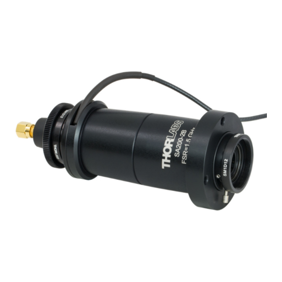
SA200-Series Scanning Fabry Perot Interferometer
DESCRIPTION:
The SA200 is a high finesse Spectrum Analyzer used to examine the fine structures of the spectral characteristics
of CW lasers. The spectrum analyzer consists of a confocal cavity that contains two high reflectivity mirrors; by
varying the mirror separation with a piezoelectric transducer the cavity acts as a very narrow band-pass filter.
Knowing the free spectral range of the SA200 allows the time-base of an oscilloscope to be calibrated to facilitate
quantitative measurements of a laser line shape.
SPECIFICATIONS:
1
FSR is set by the length of the confocal cavity and is given by: FSR=c/4d. Where d= the radius of curvature of the mirrors; in
this case d=50mm. (see drawing on next page)
2
A thermal design balances the small coefficient of thermal expansion of the Invar body with the negative coefficient of
thermal expansion of the piezo actuators.
THORLABS, INC.
1
Free Spectral Range
Measured in milliseconds
Measured in microseconds
(FSR/FWHM)
Actual Calculated Finesse:
Maximum Input Voltage:
Free Spectral Range:
Minimum Finesse:
Resolution:
Outer Housing Material:
Fabry Perot Cavity Material
Dimensions:
Confocal Cavity Configuration
Page 1 of 5
(FSR)
:
FWHM
:
150V
1.5Ghz
>200
7.5MHz
Black Anodized Aluminum
2
Low thermal expansion Invar
:
Ø 2" Flange
Total Length: 5.85"
PH. 973-579-7227
FAX 973-300-3600
technicalsupport@thorlabs.com
®
Advertisement
Table of Contents

Subscribe to Our Youtube Channel
Related Manuals for THORLABS SA200 Series


Summary of Contents for THORLABS SA200 Series
-
Page 1: Specifications
FSR is set by the length of the confocal cavity and is given by: FSR=c/4d. Where d= the radius of curvature of the mirrors; in this case d=50mm. (see drawing on next page) A thermal design balances the small coefficient of thermal expansion of the Invar body with the negative coefficient of thermal expansion of the piezo actuators. Page 1 of 5 THORLABS, INC. - Page 2 (SA201) is used to center the output on the scope. OPERATION: To set up the SA200-Series Fabry-Perot you should first mount the unit into a tip/tilt mirror mount (Thorlabs part# KM200). Attach all of the connection according the drawing on page 4. Next you should remove the detector from the back of the unit and mount it in it’s own mount, this will aid in the initial alignment.
- Page 3 R/2). This imaging of the beam back onto itself greatly simplifies the alignment of the cavity; just align your input to within a few tenths of a millimeter of the center of the mirror set and restrict your input angles to less than a few degrees. The SA200 series interferometer has two iris diaphragms that simplify this alignment requirement. Finesse The finesse of the Scanning Fabry-Perot interferometer is a quantity which characterizes the ability of the interferometer to resolve closely spaced spectral features, it defines the resolution of the instrument.
- Page 4 In a typical application the SA200 Interferometer is used in conjunction with a signal generator and an oscilloscope, as shown below in figure III. A signal generator (Thorlabs SA201 Fabry-Perot Controller is used for generating the required scan signals for obtaining the data in this document) that can produce either a triangle or saw-tooth wave with an adjustable frequency (5 to 50 Hz), an adjustable amplitude (15 to 40 volts), and an adjustable offset.
- Page 5 • Thorlabs’ KM200, 2” kinematic mount can be used to mount the SA200 Scanning Fabry Perot Interferometer. TECHNICAL SUPPORT: For further questions, or if you suspect a problem with your SA200, please contact Tech Support. An Applications Engineer will gladly assist you.
Need help?
Do you have a question about the SA200 Series and is the answer not in the manual?
Questions and answers