Sign In
Upload
Download
Table of Contents
Contents
Add to my manuals
Delete from my manuals
Share
URL of this page:
HTML Link:
Bookmark this page
Add
Manual will be automatically added to "My Manuals"
Print this page
×
Bookmark added
×
Added to my manuals
Manuals
Brands
THORLABS Manuals
Measuring Instruments
S1FC635
User manual
THORLABS S1FC635 User Manual
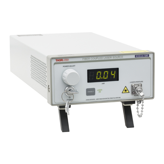
Fiber-coupled laser source
Hide thumbs
Also See for S1FC635
:
Operating manual
(12 pages)
1
2
Table Of Contents
3
4
5
6
7
8
9
10
11
12
13
14
15
16
17
18
page
of
18
Go
/
18
Contents
Table of Contents
Bookmarks
Table of Contents
Table of Contents
Chapter 1 Warning Symbol Definitions
Chapter 2 Safety
Chapter 3 Description
Chapter 4 Setup
Setting the AC Line Voltage and Installing Fuses
Initial Set-Up
Chapter 5 Operation
5.1. Front and Back Panel Overview
Turning on the Source
Adjusting the Laser Output Power
Turning the Laser off
Modulating the Laser Output
Chapter 6 Making the Safety Interlock Connections
Chapter 7 General Maintenance
Cleaning
Connector Cleaning
Chapter 8 Specifications
Chapter 9 Mechanical Drawing
Chapter 10 Regulatory
Chapter 11 Thorlabs Worldwide Contacts
Advertisement
Quick Links
1
Chapter 2 Safety
2
Chapter 3 Description
3
5.1. Front and Back Panel Overview
4
Adjusting the Laser Output Power
5
Modulating the Laser Output
6
Chapter 8 Specifications
Download this manual
See also:
Operating Manual
S1FC405, S1FC635, S1FC637,
S1FC660, S1FC675, S1FC780,
S1FC785, S1FC808, S1FC980,
S1FC1060, S1FC1310, S1FC1550
Fiber-Coupled Laser Source
User Guide
Table of
Contents
Previous
Page
Next
Page
1
2
3
4
5
Advertisement
Table of Contents
Need help?
Do you have a question about the S1FC635 and is the answer not in the manual?
Ask a question
Questions and answers
Related Manuals for THORLABS S1FC635
Measuring Instruments THORLABS S1 Series Operating Manual
Fiber coupled laser sources (12 pages)
Measuring Instruments THORLABS SA200 Series User Manual
Fabry perot interferometer (16 pages)
Measuring Instruments THORLABS SA200 Series Manual
Scanning fabry perot interferometer (5 pages)
Measuring Instruments THORLABS S120 Operating Manual
Optical power meter system (21 pages)
Measuring Instruments THORLABS S122 Operating Manual
Optical power meter system (21 pages)
Measuring Instruments THORLABS S3FC1310 User Manual
(20 pages)
Measuring Instruments THORLABS S1FC637 User Manual
Fiber-coupled laser source (18 pages)
Measuring Instruments THORLABS S1FC660 User Manual
Fiber-coupled laser source (18 pages)
Measuring Instruments THORLABS SL1310V1 Series User Manual
Swept laser (22 pages)
Measuring Instruments THORLABS SA210 Series User Manual
Fabry perot interferometer (14 pages)
Measuring Instruments THORLABS SP USB Series Operation Manual
Usb 2.0 fiber optical spectrometer (65 pages)
Measuring Instruments THORLABS SP1-USB Operation Manual
Usb 2.0 fiber optical spectrometer (65 pages)
Measuring Instruments THORLABS S2011 User Manual
Adjustable focus laser diode kit (12 pages)
Measuring Instruments THORLABS PM200 Operation Manual
Optical power and energy (74 pages)
Measuring Instruments THORLABS PM320E Operation Manual
Optical power and energy meter (70 pages)
Measuring Instruments THORLABS PM100D Operation Manuals
Optical power and energy meter (99 pages)
This manual is also suitable for:
S1fc637
S1fc660
S1fc405
S1fc780
S1fc675
S1fc785
...
Show all
S1fc808
S1fc980
S1fc1060
S1fc1310
S1fc1550
Table of Contents
Print
Rename the bookmark
Delete bookmark?
Delete from my manuals?
Login
Sign In
OR
Sign in with Facebook
Sign in with Google
Upload manual
Upload from disk
Upload from URL


Need help?
Do you have a question about the S1FC635 and is the answer not in the manual?
Questions and answers