Table of Contents
Advertisement
Quick Links
Advertisement
Table of Contents

Related Manuals for THORLABS NPL Series


Summary of Contents for THORLABS NPL Series
- Page 1 NPL Series Nanosecond Pulsed Lasers User Guide...
-
Page 2: Table Of Contents
Quick Start Guide ......................5 Chapter 4 Operation ........................6 Chapter 5 Specifications ......................9 Chapter 6 Mechanical Drawings ....................12 Chapter 7 Maintenance and Troubleshooting................15 Chapter 8 Declaration of Conformity ..................16 Chapter 9 Thorlabs Worldwide Contacts ................... 17... -
Page 3: Chapter 1 Safety Information
If equipment is used in a manner not specified by the manufacturer, the protection provided by the equipment may be impaired. Only with written consent from Thorlabs may changes to single components be carried out or components not supplied by Thorlabs be used. - Page 4 However, there is no guarantee that interference will not occur in a particular installation. Thorlabs is not responsible for any radio television interference caused by modifications of this equipment or the substitution or attachment of connecting cables and equipment other than those specified by Thorlabs. The correction of interference caused by such unauthorized modification, substitution or attachment will be the responsibility of the user.
-
Page 5: Chapter 2 Introduction
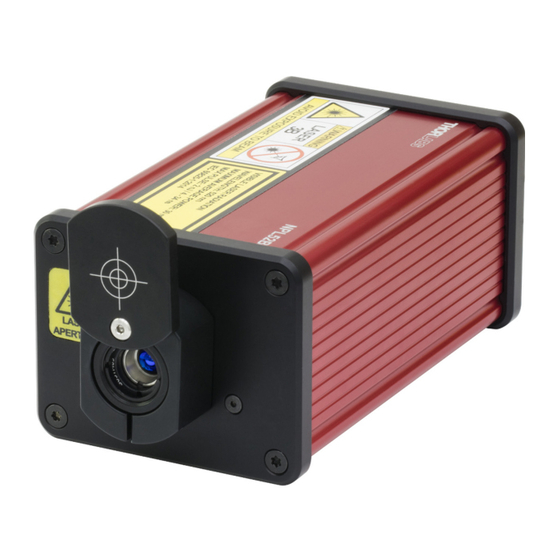
Chapter 2 Introduction The NPL series of pulsed diode lasers are designed to provide a convenient, turn-key source of nanosecond pulse trains. Model options are summarized in the table below and include different typical emission wavelengths, output powers, repetition frequency range, and fixed or adjustable pulse widths. - Page 6 Nanosecond Pulsed Lasers Chapter 2: Introduction Inputs and Controls The only differences in the back panels of the A, B, and C versions, shown below, are the pulse width and repetition rate controls. Models with Item # suffix A have neither, suffix B models have both pulse width and repetition rate control, and suffix C models have only pulse width control.
-
Page 7: Chapter 3 Quick Start Guide
1. Mount the laser head as needed using the supplied ECM225 clamps and either imperial or metric screws. After screwing the ECM225 clamps to any convenient base or post, such as one of Thorlabs’ TR series optical posts, snap the clamps on to the bottom side of the NPL housing. Firmly tighten the clamps using the locking screws. -
Page 8: Chapter 4 Operation
Figure 5 Block Diagram of the NPL Series Laser Head Power Power is supplied by the external, +15 V, wall-mounted DS15 Power Supply included with the unit and shown in the left image of Figure 6. - Page 9 The shorting device (interlock pin) installed in all units shipped from Thorlabs performs this function. Leave the shorting device installed unless using an external safety circuit or other type of remotely controlled switch to enable laser output.
- Page 10 Pulse Widths and Repetition Rates NPL series lasers with Item # suffix A and C require a user trigger input to the SMA connector on the back panel. The NPL64A laser supports rates up to 10 MHz. The C version supports rates up to 50 kHz. The slowest supported edge transition time for the trigger signal is 1 ms.
-
Page 11: Chapter 5 Specifications
Nanosecond Pulsed Lasers Chapter 5: Specifications Chapter 5 Specifications Optical Specifications Item # NPL64A NPL41B NPL45B NPL49B NPL52B Center Wavelength (Typ.) 640 ± 10 nm 405 ± 10 nm 450 ± 10 nm 488 ± 10 nm 520 ± 10 nm 6 ±... - Page 12 28 ns ± 5 ns The maximum supported edge transition time is 1 ms. Available only on NPL series lasers with Item # suffix B. Applies to external triggering (all item numbers) and internal triggering (only models with Item # suffix B).
- Page 13 Nanosecond Pulsed Lasers Chapter 5: Specifications Power, Environmental, and Physical Specifications Parameter Specification DC Input Voltage Range to Laser Head 14 V to 16 V DC Input Current to Laser Head 800 mA Max AC Input Frequency Range to DS15 Power Supply 50 Hz - 60 Hz AC Input Voltage to DS15 Power Supply 100 V to 240 V...
-
Page 14: Chapter 6 Mechanical Drawings
Nanosecond Pulsed Lasers Chapter 6: Mechanical Drawings Chapter 6 Mechanical Drawings NPL64A Figure 9 Mechanical Drawing of the NPL64A Page 12 TTN122959-D02... - Page 15 Nanosecond Pulsed Lasers Chapter 6: Mechanical Drawings NPL Series Lasers with Item # Suffix B Figure 10 Mechanical Drawing for NPL Series Lasers with Item # Suffix B Rev H, January 25, 2023 Page 13...
- Page 16 Nanosecond Pulsed Lasers Chapter 6: Mechanical Drawings NPL Series Lasers with Item # Suffix C Figure 11 Mechanical Drawing for NPL Series Lasers with Item # Suffix C Page 14 TTN122959-D02...
-
Page 17: Chapter 7 Maintenance And Troubleshooting
Do not use acetone, chemical solvents, or harsh cleaning solutions, and do not spray cleaning solutions directly onto the unit. See Section 7.2 for advice on cleaning the lens. The NPL does not contain any user-serviceable components. If malfunctions occur, please contact Thorlabs’ technical support ( ). -
Page 18: Chapter 8 Declaration Of Conformity
Nanosecond Pulsed Lasers Chapter 8: Declaration of Conformity Chapter 8 Declaration of Conformity Page 16 TTN122959-D02... -
Page 19: Chapter 9 Thorlabs Worldwide Contacts
Nanosecond Pulsed Lasers Chapter 9: Thorlabs Worldwide Contacts Chapter 9 Thorlabs Worldwide Contacts For technical support or sales inquiries, please visit us at for our most up-to-date www.thorlabs.com/contact contact information. USA, Canada, and South America UK and Ireland Thorlabs, Inc. - Page 20 www.thorlabs.com...
Need help?
Do you have a question about the NPL Series and is the answer not in the manual?
Questions and answers