Advertisement
Quick Links
Characteristics:
General description:
The HART
Termination Board model TB-D5001-HRT-003 allows the remote monitoring
®
of any HART
-compatible 4/20 mA field loop.
®
This is obtained by one locally mounted HART
ce connectors to access the relevant loops.
The single TB-D5001-HRT-003 Termination Board supports 64 channels. Yet, it could
be extended with additional TB-D5001-HRT-003 units (up to 4) to manage all 256 chan-
nels available on the HART
Multiplexer Modem 5700.
®
The Mux unit connects, via the RS-485 interface, to an external PC running an FDT-
based software package (PACTware™, etc...) through a dedicated Device Type Man-
ager (DTM). The PC can communicate with multiple Mux units, located on different
boards, in a multi-drop RS-485 mode.
The HART
Termination Board TB-D5001-HRT-003 is SIL 3 certified as non-interfering
®
with the signal loops.
Functional Safety Management Certification:
G.M. International is certified by TUV to conform to IEC61508:2010
part 1 clauses 5-6 for safety related systems up to and included SIL3.
Features:
SIL 3 according to IEC 61508:2010 Ed. 2
(see Safety Manual ISM0436 for more information).
Systematic capability SIL 3.
HART
Multiplexing Board of up to 64 analog signals (extendable to
®
256 channels with 3 additional TB-D5001-HRT-003 units).
Redundant Power Supply connection by screw terminals.
Supply is fuse protected and with LED indication.
Dedicated terminal to connect RS-485 communication cable shield.
RS-485 interface terminals to communicate with the HART
HART
channels isolated with dual capacitors (short circuit proof).
®
Spare fuse provided.
Includes hardware for Easy installation in three modes:
Wall mounting, M4 Threads,
Wall mounting, Self Threading,
Din Rail mounting.
Ordering Information:
Model:
TB-D5001-HRT-003
Accessories:
Extension cables 15 cm CABF022
Extension cables 30 cm CABF023
Extension cables 50 cm CABF024
Included:
TB-OPT-001 Universal Board mounting kit
G.M. International DTS0746-2 Page 1/5
TB-D5001
HRT-003
Multiplexer Modem 5700 and by interfa-
®
FSM
SIL 3
Mux unit.
®
Term. board flat cable 1 m CABF032
Term. board flat cable xx m CABF032/xx
.
(max 5 m)
®
SIL 3 HART
Multiplexer Termination Board
1 position for up to 64 channels (extendable
to 256 channels)
Technical Data:
Supply:
24 Vdc nom (20 to 30 Vdc) reverse polarity protected, redundant terminal blocks,
OR diodes to select higher supply source.
Connection: by polarized plug-in disconnect screw terminal blocks to accommodate
terminations up to 2.5 mm
.
2
2 LEDs indication: green.
Protection fuse: 2 A time lag (spare fuse provided on Termination Board).
HART
interface:
®
Connection: 4 flat cable 34 poles male connectors (requires female mating connector).
DC Isolation: dual capacitor for each channel.
Common mode voltage: up to 50 V.
Additional TBs interface:
Connection: 2 flat cable 10 poles male connectors (requires female mating connector).
Compatibility:
CE mark compliant, conforms to Directives:
2014/34/EU ATEX, 2014/30/EU EMC, 2014/35/EU LVD, 2011/65/EU RoHS.
Environmental conditions:
Operating: temperature limits – 40 to + 70 °C, relative humidity 95 %, up to 55 °C.
Storage: temperature limits – 45 to + 80 °C.
Safety Description:
ATEX: II 3G Ex nA IIC T4 Gc
IECEx : II 3G Ex nA IIC T4 Gc
non-sparking electrical equipment.
Approvals:
ATEX conforms to EN60079-0, EN60079-15 (pending).
IECEx conforms to IEC60079-0, IEC60079-15 (pending).
TÜV Certificate No. C-IS-272994-01 SIL 3 conforms to IEC61508:2010 Ed.2.
TÜV Certificate No. C-IS-236198-09, SIL 3 Functional Safety Certificate conforms to
IEC61508:2010 Ed.2, for Management of Functional Safety.
Mounting:
Surface (Wall) or DIN Rail mounting: TB-OPT-001 is a Kit including hardware for
mounting on wall and DIN rail.
Weight: about 200 g (excluding modules and mounting options).
Location: installation in Safe Area or Zone 2, Group IIC T4.
Dimensions: Width 176 mm, Depth 147 mm, Height 125 mm.
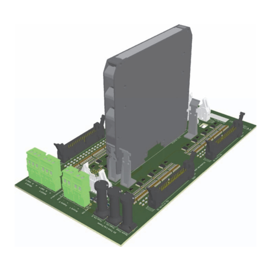
Image:
www.gminternational.com
Advertisement

Related Manuals for GMI TB-D5001


Summary of Contents for GMI TB-D5001
- Page 1 The single TB-D5001-HRT-003 Termination Board supports 64 channels. Yet, it could 2 LEDs indication: green. be extended with additional TB-D5001-HRT-003 units (up to 4) to manage all 256 chan- Protection fuse: 2 A time lag (spare fuse provided on Termination Board).
- Page 2 Termination Board Connection Diagrams: CABF022 / CABF023 / CABF024 Flat 10 poles male Protective Fuse 2 connector for additional TBs Protective Fuse 1 Spare Fuse Communication LED (yellow) Power ON 2 LED (green) Power ON 1 LED (green) CABF032 CABF032 Flat 34 poles conn.
- Page 3 Termination Board Network: Ch. 209-224 Ch. 241-256 Ch. 193-208 Ch. 225-240 DCS/PLC ... Up to 4 units Ch. 81-96 DCS/PLC Ch. 113-128 Ch. 65-80 Ch. 97-112 CABF032 Flat 34 poles cables CABF022 / Supply 1 24Vdc CABF023 / Supply 2 24Vdc CABF024 RS-485 / PC Flat 10 poles cable...
- Page 4 4/20 mA si g nals 5700 5700 5700 HART transmitters ® and valve positioners GMI TB 1 Barriers HART Si g nal GMI TB 2 Barriers Up to 4 TB-D5001-HRT-003 2) Isolators on Termination Boards (Non-IS Loops) Workstation PC Process control system e.g. DCS,PLC...
- Page 5 Connections table: FLAT FLAT FLAT FLAT CHANNEL NUMBER CONNECTOR PIN (+) CONNECTOR PIN (-) CHANNEL NUMBER CONNECTOR PIN (+) CONNECTOR PIN (-) 1 (CON1) 2 (CON1) 1 (CON3) 2 (CON3) 3 (CON1) 4 (CON1) 3 (CON3) 4 (CON3) 5 (CON1) 6 (CON1) 5 (CON3) 6 (CON3)
Need help?
Do you have a question about the TB-D5001 and is the answer not in the manual?
Questions and answers