Advertisement
Quick Links
LF Wake-up Demonstrator ATAK5276-83
1. General Description
ATAK5276-83 is intended to demonstrate the performance of an LF wake-up channel
needed for battery-driven systems. Typical wake-up applications can be found in
vehicles for Tire Pressure Monitoring (TPM).
The demonstrator hardware (HW) consists of the LF transmitter board (ATAB5276)
patched onto a microcontroller base board and an LF receiver board (ATAB5283).
The high antenna driver ability of the transmitter, combined with the sensitive receiver,
enables a wake-up distance of up to 2.5 meters.
For the general functionality of the ATA5276 and the ATA5283 please refer to the
related datasheets.
2. System Configuration
Figure 2-1.
LF Wake-up Demonstration System
ATAK5276-83
LF Wake-up
Demonstrator
Application Note
4857C–AUTO–07/06
Advertisement

Related Manuals for Atmel ATAK5276-83


Summary of Contents for Atmel ATAK5276-83
- Page 1 LF Wake-up Demonstrator ATAK5276-83 ATAK5276-83 1. General Description ATAK5276-83 is intended to demonstrate the performance of an LF wake-up channel LF Wake-up needed for battery-driven systems. Typical wake-up applications can be found in vehicles for Tire Pressure Monitoring (TPM). Demonstrator The demonstrator hardware (HW) consists of the LF transmitter board (ATAB5276) patched onto a microcontroller base board and an LF receiver board (ATAB5283).
-
Page 2: Components Included
That file includes the preamble protocol for waking up the receiver; followed by modula- tion data, switching on the LED indicator on the receiver board. With the continuous carrier mode selection, the field can be switched on steadily (this feature is useful for antenna evalua- tion or field strength measurements). ATAK5276-83 4857C–AUTO–07/06... -
Page 3: Hardware Components
ATAK5276-83 Figure 3-1. Command Settings on the Host Screen 4. Hardware Components Transmitter Board ATAB5276_V1 with External Antenna Module Figure 4-1. Transmitter Board ATAB5276_V1 4857C–AUTO–07/06... - Page 4 Typical Parameters of Antenna Module Coil Inductance: = 345 [µH] ±5% Coil Resistance: = 2.5 [Ω] Impedance: = 271 [Ω] Module Series Resistor: RANT (R1) = 10 [Ω] Series Capacitor: 4.7 nF/1400V Total Q-Factor: = 22 ATAK5276-83 4857C–AUTO–07/06...
- Page 5 ATAK5276-83 Figure 4-3. Schematic of the Transmitter Board ATAB5276_V1 State Machine Gate Driver Control Half Bridge Driver 4857C–AUTO–07/06...
- Page 6 PCB test terminal Black DVCC, VCC PCB test terminal X1–X2 Connector 18 pin ® Antenna plug PN 175781-1 Tyco Electronics ® Power plug (2.1 mm) Cliff Electronics J1-J3 Header 2 pole (J1-J3) Jumper 2.54 mm Board ATAB5276 V1.0/1.5 mm Atmel ATAK5276-83 4857C–AUTO–07/06...
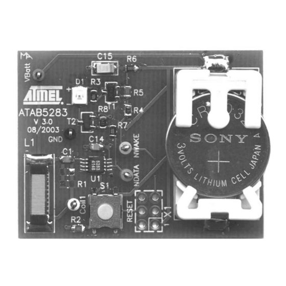
- Page 7 ATAK5276-83 Receiver Board ATAB5283 The receiver IC ATA5283 is equipped with a 1D LF antenna on-board. Received data is indicated by an LED display. Once data is received, the IC can be returned to STANDBY mode by pressing the RESET button. Test pins allow the measurement of all relevant signals.
- Page 8 Additionally, an LED is used to indicate the received data protocol. Test points and a pin socket allow the measurement of all relevant sig- nals. A 3V lithium battery is used, supplying the receiver with LED indication. ATAK5276-83 4857C–AUTO–07/06...
- Page 9 ATAK5276-83 Figure 4-6. Receiver Board ATAB5282_V4 Figure 4-7. Schematic of Receiver Board ATAB5282_V4 COIL1 Lith COIL1 ATA5282 COIL2 NWAKE/ COIL2 DATA NWAKE COIL3 COIL3 NSCL NSCL TSSOP8 NSCL R4/1+ R4/2 NWAKE 4857C–AUTO–07/06...
- Page 10 Resistor 100 kΩ SMD 0805 Resistor 100Ω SMD 0805 Resistor 100Ω SMD 0805 Bridge 10 kΩ SMD 0805 Vbatt1 Battery holder Li-Cell 3V/ 220 mAh CR2032 7 pcs Test Pins 1 pcs Test Socket 2 x 3 pole ATAK5276-83 4857C–AUTO–07/06...
- Page 11 ATAK5276-83 5. Demonstrator: Getting Started 1. Build up the demonstrator system according to the configuration shown in Figure 2-1 on page 2. Install the demonstration software by executing setup.exe and following the menu instructions. If, during the installation process, the proposed default folder is accepted, the path of ATA5276.exe is as follows:...
- Page 12 13). The ATA5283.dat protocol con- sists of a preamble followed by data which will be indicated by LED. In contrast, the ATA5282 requires, in addition, a header ID after the preamble before data are sent. These patterns are offered by ATA5282.dat file. ATAK5276-83 4857C–AUTO–07/06...
- Page 13 ATAK5276-83 Figure 6-3. Select Data Files 5. When the send button is pressed, the loaded protocol (pattern) is sent by the transmit- ter (see Figure 6-4). By default single operation mode is enabled, meaning that the protocol is sent once when the send button is pressed. In loop operation, the protocol is sent continuously.
-
Page 14: Error Diagnosis
1 . 5 A p d e t e r m i n e d b y RCR = RCR1//RCR2 = 25 kΩ. Figure 6-6. Antenna Current out of Regulation ATAK5276-83 4857C–AUTO–07/06... - Page 15 ATAK5276-83 To reach the current regulation level of 1.5 Ap (see Figure 6-7), the series resistor RANT (R1) on the antenna module has to be shorted. In this case, the antenna quality factor is increased to Q = 108. Due to the high Q-factor, the current regulation leads to a short overswing during the switch-on phase.
- Page 16 A similar protocol transmission to the 3D receiver is shown in Figure 6-9. Due to the header detection, the Q-factor of the transmitter antenna module is reduced to a value of Q = 13 (RANT = 18Ω). Figure 6-9. Signal Transmission ATAB5276 Transmitter to ATAB5282 Receiver ATAK5276-83 4857C–AUTO–07/06...
- Page 17 Disclaimer: The information in this document is provided in connection with Atmel products. No license, express or implied, by estoppel or otherwise, to any intellectual property right is granted by this document or in connection with the sale of Atmel products. EXCEPT AS SET FORTH IN ATMEL’S TERMS AND CONDI- TIONS OF SALE LOCATED ON ATMEL’S WEB SITE, ATMEL ASSUMES NO LIABILITY WHATSOEVER AND DISCLAIMS ANY EXPRESS, IMPLIED OR STATUTORY...
Need help?
Do you have a question about the ATAK5276-83 and is the answer not in the manual?
Questions and answers