Table of Contents
Advertisement
Quick Links
Advertisement
Table of Contents

Related Manuals for L-Acoustics LA-RAK


Summary of Contents for L-Acoustics LA-RAK
- Page 1 LA-RAK user manual...
- Page 2 Document Reference: LARAK_UM_EN_2.0 _________________ © Copyright 2017 by L-ACOUSTICS ® Parc de la Fontaine de Jouvence, 91462 Marcoussis cedex, France _________________ Distribution date: February 23, 2017 w w w . l - a c o u s t i c s . c o m...
-
Page 3: Safety Warnings
All information hereafter detailed applies to the L-ACOUSTICS LA-RAK Touring Rack, designated in this section ® as the product. The LA-RAK product includes the following components: a RK 9U cabinet, three LA8 amplified controllers and three distribution panels (LA-POWER, LA-PANEL and LA-PANEL AES3). Symbol description 1.1.1... -
Page 4: Important Safety Instructions
1. Read this manual 2. Heed all safety warnings 3. Follow all instructions 4. The user should never incorporate equipment or accessories not approved by L-ACOUSTICS ® 5. Environments Use the product only in E1, E2, E3, or E4 environments according to EN55103-2 standard. - Page 5 Do not attempt to service any product component as removing covers may expose to dangerous voltage or other hazards. VOLTAGE All service and repair work must be carried out by an L-ACOUSTICS ® authorized dealer. The use of unauthorized replacement parts may result in injury and/or damage through fire, electric shock, or other electricity-related hazards.
- Page 6 Load capacity and setup safety limits outlined in this manual must never be exceeded. WARNING 27. Local regulations Some countries require higher Ultimate Strength Safety Factors and specific rigging approvals. It is the user’s responsibility to ensure that any overhead suspension of L-ACOUSTICS ® systems has been made in WARNING accordance with all applicable local regulations.
-
Page 7: Ec Declaration Of Conformity
13 rue Levacher Cintrat Parc de la Fontaine de Jouvence 91462 Marcoussis Cedex France States that the following products: LA-RAK touring rack, composed of: Rack cabinet, RK 9U; Amplified controllers, LA8; Distribution panels, LA-POWER, LA-PANEL and LA-PANEL AES3. LA-RAK BUMP flying frame. -
Page 8: Table Of Contents
Unpacking ................................7 Cross-references ..............................8 Web links ................................. 8 SYSTEM APPROACH BY L-ACOUSTICS ® LA-RAK as a signal, network and power distribution system .................. 9 L-ACOUSTICS ® components related to LA-RAK ....................9 Supported configurations ............................11 LA-RAK TOURING RACK Global architecture .............................. -
Page 9: Introduction
Be sure to save the carton and packing materials for the carrier's inspection. The LA-RAK package consists of the following components (see from Figure 4 to Figure 7): One L-ACOUSTICS ®... -
Page 10: Cross-References
All along the manual, a bracketed number refers to a section. For example, [3.3] stands for the present section: Cross- references. Web links Please check the L-ACOUSTICS ® web site on a regular basis for latest document and software application updates. -
Page 11: System Approach By L-Acoustics
LA8 amplified controller. It offers an advanced rack solution for all L-ACOUSTICS systems covering signal, power and network distribution in a comprehensive plug and play touring package. LA-RAK was created as a universal platform designed to facilitate cross-rental and to ensure compatibility with the legacy cabling standard of L- ACOUSTICS ®... - Page 12 KUDO ARCS SB18 V-DOSC dV-DOSC SB18i KARA K1-SB SB28 KARAi Figure 1: Main system components related to the LA-RAK w w w . l - a c o u s t i c s . c o m LARAK_UM_EN_2.0...
-
Page 13: Supported Configurations
The LA-RAK working principle is entirely modular, so that the engineer can physically assemble and interconnect multiple elements to fit numerous applications. The LA-RAK configuration based on a multiple of 3 LA8 yields the maximum flexibility and power resources for any L-ACOUSTICS system, from compact coaxial systems up to KUDO ®... -
Page 14: La-Rak Touring Rack
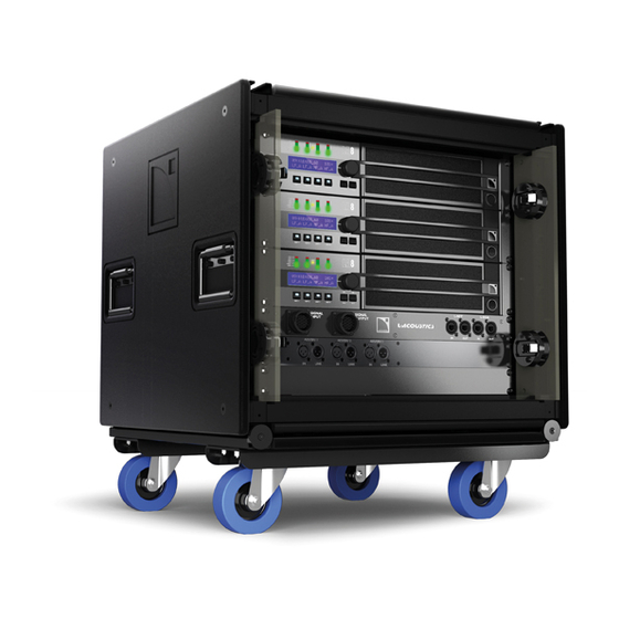
5 LA-RAK TOURING RACK Global architecture The L-ACOUSTICS LA-RAK is a 9U rack cabinet in which are mounted three LA8 amplified controllers, as well as ® three distribution panels: LA-POWER for power, LA-PANEL for analog signals and network, and LA-PANEL AES3 for digital audio signals. -
Page 15: Rk 9U
® sockets. The RK 9U is equipped in standard with a detachable transport dolly board and two coupling bars. These last also allow arraying several LA-RAK in flown or stacked configurations. Steel frame Retractable door storage slot (x2) Aluminum frame... -
Page 16: La8 Amplified Controllers
M5 screws (the “M5” notation refers to the European standard, see applicable external documentation). ® Note: See Appendix 0 for LA-POWER US description or contact a local L-ACOUSTICS representative for any country located outside Europe and USA. -
Page 17: La-Panel
LA-PANEL The L-ACOUSTICS ® LA-PANEL allows distribution of 6 analog audio signals. The LA-RAK is fed with the signals through the SIGNAL INPUT 19-point PA-COM ® connector. The signals can be distributed to the 3 amplifiers thanks to ® 6 OUT XLR3 connectors on the rear side of the panel. The SIGNAL OUTPUT 19-point PA-COM connector allows ®... -
Page 18: Installation
CAUTION Moving and transporting the LA-RAK The removable dolly board (see Figure 10) is for moving and transporting a vertical array of two LA-RAK. It secures to the bottom LA-RAK using two coupling bars (see [6.4]). For moving or transporting purposes, a maximum of two LA-RAK can be set onto one dolly board. - Page 19 Apply the following procedure to retract and lock the LEXAN doors: ® a. Detach both doors and slide them along both LA-RAK sides (between the outer aluminum frame and the inner steel frame). b. Insert and lock both ball locking pins through each door’s bottom hole.
-
Page 20: Rigging The La-Rak
Repeat for the second coupling bar. Figure 10: Removing the dolly board from the LA-RAK Lift up the second LA-RAK and install it on the first one: align the rails and set the stacking runners into the runner guides. - Page 21 Secure a third LA-RAK by repeating the steps from 2 to 4. A maximum of three LA-RAK can be stacked onto one dolly board. Secure the stacked LA-RAK assembly to the structure, platform, or stage using ratchet strap or any other applicable device.
- Page 22 LA-RAK TOURING RACK user manual VERSION 2.0 Figure 12: Three stacked LA-RAK (maximum configuration) w w w . l - a c o u s t i c s . c o m LARAK_UM_EN_2.0...
- Page 23 ® LA-RAK BUMP flying frame is engineered to fly 4 LA-RAK for a drive capacity of up to 24 K1 enclosures. It can be flown using single pick-point and secured to an additional safety point. It is assembled with bolts for mechanical integrity visual check and is protected by polyester-coating to enhance weather resistance.
- Page 24 Bring a second LA-RAK under the rigging point. Remove both coupling bars by repeating step 2. Lower the first LA-RAK so as to set it on the second one: align the rails and set the stacking runners into the runner guides.
- Page 25 WARNING 12. Raise the LA-RAK array at desired height. Secure the LA-RAK flown array to the main structure using the SAFETY shackle (see Figure 15) and a sling. WARNING w w w . l - a c o u s t i c s . c o m...
- Page 26 LA-RAK TOURING RACK user manual VERSION 2.0 Figure 17: Four flown LA-RAK (maximum configuration) 6.4.3 Flying procedure using the K1-BUMP Please refer to the K1 Rigging Procedures manual [3.4]. w w w . l - a c o u s t i c s . c o m...
-
Page 27: Connecting La-Rak To Ac Mains
® VOLTAGE A second LA-RAK can be plugged in the female LINK OUT outlet of the first LA-RAK to be powered in parallel. Powering two LA-RAK in parallel is only possible in the 230 V (±10 %) countries. In this case a maximum of two LA-RAK can be powered in parallel by one AC mains outlet. - Page 28 VERSION 2.0 6.5.2 LA-POWER mono-phase circuits Connect LA-RAK to AC mains only if the operating voltage indicated on the LA8 back panels corresponds to the local AC mains rating. VOLTAGE Two LA8 versions are available (also refer to the LA8 User Manual [3.4]): ...
-
Page 29: Analog Audio Cabling
Analog audio cabling 6.6.1 Internal cabling With analog audio, routing modularity is achieved through internal cabling, whereas external cabling uses a constant scheme (see [6.6.2]). An XLR connection panel located on the rear side of the LA-PANEL and a set of six XLR cables allow distributing up to six different analog audio signals to the LA8 amplified controllers. - Page 30 With analog audio, external cabling uses a constant scheme that allows feeding a LA-RAK, or a LA-RAK daisy-chain, with up to 6 signals. For any LA-RAK, the internal cabling (see [6.6.1]) determines how many channels are used, which ones, and which amplifier receives them.
- Page 31 OUTPUT SIGNAL connector on LA-PANEL INPUT SIGNAL connector on LA-PANEL DOM2, DOM30 or DOM45 DOMP-2 DOMF ANALOG AUDIO SOURCE DOM2 To additional signal DOMM processing devices (optional use) Figure 23: Feeding three LA-RAKs with 6 analog audio signals w w w . l - a c o u s t i c s . c o m LARAK_UM_EN_2.0...
-
Page 32: Digital Audio Cabling
LA-RAK TOURING RACK user manual VERSION 2.0 Digital audio cabling 6.7.1 Internal cabling With digital audio, internal cabling uses a constant scheme. As digital audio requires an active refresh of the signal that is provided by the LA-AES3 card, routing modularity is achieved through external cabling [6.7.2]. The only internal cabling scheme that should be used is shown in Figure 24. - Page 33 6.7.2 External cabling With digital audio, routing of the signals is achieved in a convenient and flexible manner through external cabling, by using the patch panel on the front of the LA-PANEL AES3 . Two examples are given in Figure 26 and Figure 27. Up to six digital audio signals can be routed from an AES/EBU digital audio source (mixing console or EQ device) to the LA-PANEL AES3 via three XLR3 cables, each one conveying two channels.
- Page 34 LINK connector on LA-PANEL AES3 IN connector on LA-PANEL AES3 Figure 26: Feeding three LA-RAK with three pairs of digital audio signals w w w . l - a c o u s t i c s . c o m...
- Page 35 AES / EBU STEREO DIGITAL AUDIO SOURCE External daisy-chaining Internal daisy-chaining Figure 27: Digital audio cabling with LA-RAK – FOH example w w w . l - a c o u s t i c s . c o m LARAK_UM_EN_2.0...
-
Page 36: Loudspeaker Cabling
TOURING RACK user manual VERSION 2.0 Loudspeaker cabling The rear side of the LA-RAK gives access to the output connection panel of each LA8. For each amplifier, this panel feature one CA-COM ® connector, as well as three SpeakON ®... -
Page 37: L-Net Network Cabling
The cable linked to the OUT connector on the back of LA-PANEL allows getting back the network signal from the L- NET OUT connector of a LA8, to send it towards another LA-RAK and set up an external daisy-chain topology. - Page 38 Daisy-chain: The IN connector of a first LA-RAK is linked to the computer driving LA NETWORK MANAGER. The network is then set up by linking the OUT connector of each LA-RAK to the IN connector of the following LA-RAK in the chain.
- Page 39 LA NETWORK MANAGER CAT 5e U/FTP cable ETHERNET ® SWITCH (not provided) Figure 33: L-NET external cabling – option 2: star topology CAT 5e U/FTP cable ETHERNET ® SWITCH LA NETWORK MANAGER Figure 34: L-NET external cabling – option 3: hybrid topology w w w .
-
Page 40: Care And Maintenance
Screws and rigging points resistant to oxidation. However, in order to ensure product performance and safety, it is essential to frequently inspect the LA-RAK and its internal components. These checks need to be done on a regular basis depending on the conditions of system use and are described in section [7.2]. -
Page 41: Network Cables Replacement Procedure
Network cables replacement procedure When leaving the factory the LA-PANEL features four CAT5e U/FTP cables. If cables replacement is needed follow the procedure below: a. Remove the LA-PANEL from the LA-RAK by removing the four front Pozidriv ® screws. ®... -
Page 42: Specifications
BUMP flying frame (available with the K1 system, refer to components the K1 Rigging Procedures manual [3.4] ). Vertical stacking Certified for up to 3 LA-RAK onto the dolly board. Moving & transporting Certified for up to 2 LA-RAK onto the dolly board. Materials Polyethylene, aluminum, and steel. - Page 43 581 x 102 x 558 mm / 22.9 x 4 x 22 in Weight 13.5 kg / 29.7 lbs Setup safety limits Maximum of 4 LA-RAK per LA-RAK BUMP. Material Polyester-coated steel. Complementary accessories 2 x ⅝” shackles w w w . l - a c o u s t i c s . c o m...
- Page 44 LA-RAK TOURING RACK user manual VERSION 2.0 Reference LA8 amplified controller Dimensions (W x H x D) Weight 88,1 (2U) x 483 x 420 mm / 3.5 (2U) x 19 x 16.5 in 12.3 kg / 26.9 lbs Output power EIA (1% THD, 1 kHz, all channels driven) 4 x 1100 W at 8 Ω...
-
Page 45: Appendix: La-Power Us
LA-RAK and LA-POWER US presentation A 120 V version of the LA-RAK touring rack is also available for use in the USA and countries using the same electric standards. It features the same characteristics as the European version except for the power panel, which is referenced as the LA-POWER US. - Page 46 9.2.2 LA-POWER US mono-phase circuits Connect LA-RAK US to AC mains only if the operating voltage indicated on the LA8 back panels corresponds to the local AC mains rating. Two LA8 versions are available (also refer to the LA8 User Manual [3.4]): VOLTAGE ...
- Page 47 L-Acoustics, an L-Group Company 13 rue Levacher Cintrat – 91460 Marcoussis – France +33 1 69 63 69 63 – info@l-acoustics.com www.l-acoustics.com L-Acoustics GmbH L-Acoustics Ltd. L-Acoustics Inc. Steiermärker Str. 3-5 PO. Box Adler Shine - Aston House 2645 Townsgate Road, Suite 600...
Need help?
Do you have a question about the LA-RAK and is the answer not in the manual?
Questions and answers