
Related Manuals for L-Acoustics LA-RAK


Summary of Contents for L-Acoustics LA-RAK
- Page 1 LA- - - - RAK TOURING RACK TOURING RACK TOURING RACK TOURING RACK user manual user manual user manual user manual VERSION 1.0 VERSION 1.0 VERSION 1.0 VERSION 1.0 w w w . l - a c o u s t i c s . c o m...
-
Page 3: Safety Warnings
All information hereafter detailed applies for the L-ACOUSTICS LA-RAK Touring Rack designated in this section as ‘‘the product’’. The LA-RAK product includes the following components: RK 9U cabinet, LA-POWER power distribution panel, LA-PANEL signal distribution panel, and LA8 amplified controllers. -
Page 4: Important Safety Instructions
2. Heed all safety warnings 3. Follow all instructions ® 4. The user should never incorporate equipment or accessories not approved by L-ACOUSTICS Environments Use the product only in E1, E2, E3, or E4 environments according to EN55103-2 standard. IMPORTANT... - Page 5 Do not attempt to service any product component as removing covers may expose to dangerous voltage or other hazards. ® All service and repair work must be carried out by an L-ACOUSTICS authorized dealer. The use of unauthorized replacement parts may result in injury and/or damage through fire, electric VOLTAGE shock, or other electricity-related hazards.
- Page 6 ® manufactured by L-ACOUSTICS It is the user’s responsibility to ensure that the Working Load Limit (WLL) of all additional hardware rigging accessories is greater than the total weight of the rack assembly in use.
- Page 7 27. Local regulations Some countries require higher Ultimate Strength Safety Factors and specific rigging approvals. It is the ® user responsibility to ensure that any overhead suspension of L-ACOUSTICS systems has been made in accordance with all applicable local regulations.
-
Page 8: Ec Declaration Of Conformity
Parc de la Fontaine de Jouvence 91462 Marcoussis Cedex France States that the following products: Touring rack, LA-RAK (composed of the: Rack cabinet, RK 9U Amplified controllers, LA8 Power distribution panel, LA-POWER Signal distribution panel, LA-PANEL) Flying frame, LA-RAK BUMP... -
Page 9: Table Of Contents
Amp cooling ..............................22 Connecting LA-RAK to AC mains........................23 6.5.1 LA-POWER three-phase circuit ......................23 6.5.2 LA-POWER mono-phase circuits ......................24 Connecting LA-RAK to analog audio source .....................25 6.6.1 External analog audio connection......................25 6.6.2 Internal analog audio connection.......................27 Connecting LA-RAK to L-NET network......................28 6.7.1... -
Page 10: Introduction
If found to be damaged, notify the shipping company or the distributor immediately. Only the consignee may initiate a claim with the carrier for damage incurred during shipping. Be sure to save the carton and packing materials for the carrier's inspection. The LA-RAK package consists of the following components (see from Figure 4 to Figure 7): • ®... -
Page 11: La-Rak Signal & Power Distribution System
DOM2 and DOM30 analog signal cables with respective lengths of 2 m/6.5 ft and 30 m/100 ft. These cables are for connecting an analog sound source (mixing console or EQ device) to the LA-RAK or for linking two LA-RAK. Each cable ®... - Page 12 ® ARCS dV-SUB V-DOSC dV-DOSC SB118 K1-SB 115XT HiQ SB28 ® Figure 1: L-ACOUSTICS components which connect to the LA-RAK w w w . l - a c o u s t i c s . c o m LARAK_UM_EN_1.0...
- Page 13 The LA-RAK working principle is entirely modular and the engineer can physically assemble and interconnect multiple elements to fit numerous applications. The LA-RAK configuration based on a multiple of 3 LA8 yields the maximum ® ® flexibility and power resources for any L-ACOUSTICS...
-
Page 14: La-Rak Touring Rack
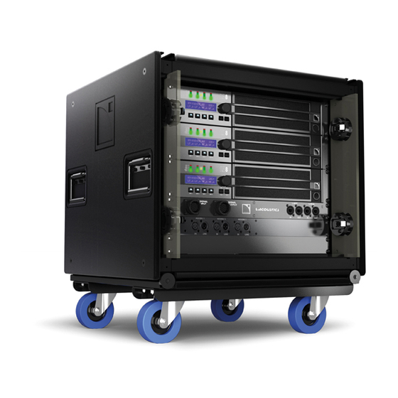
LA-RAK is composed of the RK 9U cabinet in which are mounted three LA8 amplified controllers as well as the LA-POWER and LA-PANEL power and signal distribution panels. In addition, the LA-RAK can be flown under the LA-RAK BUMP flying frame. - Page 15 (see section 6.8). The RK 9U is equipped in standard with a detachable transport dolly board and two coupling bars. These last also allow arraying several LA-RAK in flown or stacked configurations. Steel frame Retractable door storage slot (x2)
- Page 16 M5 screws (the “M5” notation refers to the European standard, see applicable external documentation). ® Note: See Appendix 9 for LA-POWER US description or contact a local L-ACOUSTICS representative for any country located outside Europe and USA.
- Page 17 The L-ACOUSTICS LA-RAK BUMP flying frame is engineered to fly 4 LA-RAK for a drive capacity of up to 24 K1 enclosures. It can be flown using single pick-point and secured to an additional safety point. It is assembled with bolts for mechanical integrity visual check and is protected by polyester-coating to enhance weather resistance.
-
Page 18: Installation
CAUTION Shipping the LA-RAK The removable dolly board (see Figure 9) is for shipping a vertical array of up to two LA-RAK. It secures to the bottom LA-RAK using two coupling bars (see section 6.3). It is recommended to use the removable dolly board for shipping the LA-RAK. - Page 19 Repeat for the second coupling bar. Figure 9: Removing the dolly board from the LA-RAK Lift up the second LA-RAK and put it onto the first one: align the rails and put the stacking runners onto the runner guides.
- Page 20 VERSION 1.0 Put a third LA-RAK onto the second one by repeating the steps from 2 to 4. A maximum of three LA-RAK can be stacked onto one dolly board. Secure the LA-RAK stacked assembly to the structure, platform, or stage using ratchet strap or any other applicable device.
-
Page 21: Flying Procedure Using The La-Rak Bump
Figure 13: Rigging LA-RAK BUMP to LA-RAK Raise the LA-RAK BUMP/LA-RAK assembly at 0.7 m/2 ft height: the dolly board should separate from the array. Put a second LA-RAK under the rigging point. w w w . l - a c o u s t i c s . c o m... - Page 22 VERSION 1.0 Remove both coupling bars by repeating step 2. Lower the first LA-RAK so as to install it onto the second one: align the rails and put the stacking runners onto the runner guides. 10. Secure the first LA-RAK to the second one (use both preceding coupling bars): a.
-
Page 23: Flying Procedure Using The K1-Bump
12. Raise the LA-RAK array at desired height. Secure the LA-RAK flown array to the main structure using the “SAFETY” shackle (see Figure 13) and a sling. WARNING Figure 15: Four flown LA-RAK (maximum configuration) 6.3.3 Flying procedure using the K1-BUMP ®... -
Page 24: Amp Cooling
Apply the following procedure to retract and lock the LEXAN doors: a. Detach both doors and slide them along both LA-RAK sides (between the outer aluminum frame and the inner steel frame). b. Insert and lock both ball locking pins through each door’s bottom hole. -
Page 25: Connecting La-Rak To Ac Mains
VOLTAGE A second LA-RAK can be plugged in the female LINK OUT socket of the first LA-RAK to be powered in parallel. Powering two LA-RAK in parallel is only possible in the 230 V (±10 %) countries. -
Page 26: La-Power Mono-Phase Circuits
6.5.2 LA-POWER mono-phase circuits Connect LA-RAK to AC mains only if the operating voltage indicated on the LA8 back panels corresponds to the local AC mains rating. Two LA8 versions are available (also refer to the “LA8 – User Manual”): •... -
Page 27: Connecting La-Rak To Analog Audio Source
Several additional LA-RAK can be cascaded in parallel by linking each “SIGNAL OUTPUT” socket to the following LA- RAK “SIGNAL INPUT” socket. The six analog audio signals can also be routed from the last LA-RAK to other signal processing devices using the DOMM cable. - Page 28 VERSION 1.0 ® The following chart and figure describe the L-ACOUSTICS analog audio cables: ® Table 1: L-ACOUSTICS analog audio cable set description Cable Length Input connector(s)
-
Page 29: Internal Analog Audio Connection
6.6.2 Internal analog audio connection An XLR patch panel located on the rear side of the LA-PANEL and a set of six XLR cables allow distributing up to six different analog audio signals (see section 6.6.1) to the LA8 amplified controllers. As the possible internal audio cabling schemes are numerous only two representative ones are shown in Figure 21: a. -
Page 30: Connecting La-Rak To L-Net Network
The LA-PANEL front side features two L-NET Ethercon I/O sockets to connect several LA-RAK within the L-NET network (see Figure 23). A maximum of 253 LA8 can be interconnected within the same network (84 LA-RAK + 1 LA8). IMPORTANT External L-NET sockets Figure 23: LA-PANEL front view w w w . - Page 31 The L-NET connectors located on the LA-PANEL allow connection of the LA-RAK touring racks and the computer (driving LA NETWORK MANAGER software) to the L-NET network. The three following figures show external L-NET cabling principles for the daisy-chain, star, and hybrid network topologies:...
- Page 32 LA- - - - RAK T T T T OURING RACK OURING RACK OURING RACK OURING RACK u u u u ser ser m m m m anual anual anual anual VERSION 1.0 CAT 5e U/FTP cable ® ETHERNET SWITCH LA NETWORK MANAGER Figure 26: L-NET external cabling –...
-
Page 33: Internal Digital Connection
When leaving the factory the LA-PANEL features four CAT5e U/FTP cables. If cable replacement is needed follow the procedure below (see also Figure 28): ® a. Remove the LA-PANEL from the LA-RAK by removing the four front Pozidriv screws. ®... - Page 34 Digital cabling schemes Both possible internal L-NET cabling schemes are shown in the following figure. The star network topology requires an additional switch (not provided) that can be mounted in the available 2U space located on the LA-RAK: CAT 5e U/FTP cables...
-
Page 35: Connecting Loudspeakers To La-Rak
Connecting loudspeakers to LA-RAK ® ® On the LA-RAK rear face the three LA8 central parts contain a set of 3 CA-COM and 6 Speakon connectors that offers the same functionality as a speaker output patch panel. Please refer to appropriate enclosure User Manuals as well as “LA8 - User Manual’’ (all available on the ®... -
Page 36: Care And Maintenance
Screws and rigging points resistant to oxidation. However, in order to ensure product performance and safety, it is essential to frequently inspect the LA-RAK and its internal components. These checks need to be done on a regular basis depending on the conditions of system use. The testing procedure consists of three steps as described in section 7.2. -
Page 37: Spare Parts And Recommended Tools
CA RK9UCACHE 1U blank panel RKENTR Spacer to fix the LA8 rear part to the LA-RAK LA8 / LA8 US / LA8 JP Amplified controller 4 x 1800 W @ 4 for Europe / USA / Japan LAPANEL... -
Page 38: Specifications
Certified for up to 4 LA-RAK onto the L-ACOUSTICS K1-BUMP flying frame (available with the K1 system, refer to the “K1 – Rigging Procedures” manual). Captive rigging components. Certified for up to 3 LA-RAK onto the dolly board. Vertically stacking or shipping External Structure Materials Polyethylene, aluminum, and steel. - Page 39 Dimensions (W x H x D) 581 x 102 x 558 mm / 22.9 x 4 x 22 in Weight 13.5 kg / 29.7 lbs Setup safety limits Maximum of 4 LA-RAK per LA-RAK BUMP. Polyester-coated steel. Material Complementary accessory 2 x ⅝” shackles w w w .
-
Page 40: Appendix: Connecting The La-Power Us
LA-RAK and LA-POWER US presentation A 120 V version of the LA-RAK touring rack is also available for use in the USA. It features the same characteristics as the European version except for the mains power block as referenced as the LA-POWER US. - Page 41 ® The L-ACOUSTICS LA-POWER US is a 2U/19” I/O 120 V power distribution panel featuring a 30 A three-phase L-21 IN/THRU socket. This configuration allows the power to be automatically balanced with one LA8 per phase. Three L5-30 AC outlets (L1, L2, and L3) are available for LA8 and six additional duplex outlets (2 front and 4 rear) are ®...
-
Page 42: Connecting La-Rak Us To Ac Mains
Contact a local L-ACOUSTICS distributor for countries in which this standard does not apply. VOLTAGE A maximum of one LA-RAK can be connected per AC mains outlet. Never use the female L-21 THRU socket. CAUTION 120 V / 30 A... -
Page 43: La-Power Us Mono-Phase Circuits
9.2.2 LA-POWER US mono-phase circuits Connect LA-RAK US to AC mains only if the operating voltage indicated on the LA8 back panels corresponds to the local AC mains rating. Two LA8 versions are available (also refer to the “LA8 – User Manual”): •... - Page 44 Document Reference: LARAK_UM_EN_1.0 _________________ ® © Copyright 2009 by L-ACOUSTICS Parc de la Fontaine de Jouvence, 91462 Marcoussis cedex, France _________________ Distribution date: July 20 , 2009 w w w . l - a c o u s t i c s . c o m...
Need help?
Do you have a question about the LA-RAK and is the answer not in the manual?
Questions and answers