Table of Contents
Advertisement
Quick Links
Advertisement
Table of Contents

Related Manuals for ThermoFisher Scientific HERASAFE 2025


Summary of Contents for ThermoFisher Scientific HERASAFE 2025
- Page 1 Valid: 30.08.2017 / 50155204...
- Page 2 Copyright 2019 These operating instructions are protected by copyright. Rights resulting thereof, particularly reprint, photomechanical or digital postprocessing or reproduction, even in part, are only allowed with the written consent of Thermo Electron LED GmbH. This regulation does not apply to reproductions for in-plant use. Trademarks Thermo Scientific is a brand of Thermo Fisher Scientific.
-
Page 3: Table Of Contents
Table of Contents Chapter 1 Table of Contents ............................... 3 Chapter 1 Figures ................................7 Chapter 1 General Notes..............................9 General Safety Instructions........................... 10 Warranty ..............................10 Explanation of Symbols ..........................11 Symbols used in the Operating Instructions ....................11 Symbols on the Device .......................... - Page 4 Table of Contents Chapter 6 Operation ................................. 39 Display................................ 39 Explanation of the Display Components ....................39 Display in OFF-Mode ..........................40 Display in Work-Mode ..........................40 Power Interruption ..........................40 Display and Functions after a Power Failure ..................... 40 Failure Messages ...........................
- Page 5 Table of Contents Chapter 10 Maintenance ..............................63 Inspection ..............................63 Service ............................... 63 UV Lamps .............................. 63 Sample Chamber Illumination ........................64 Replacing the Front Cover Seal ........................ 64 Retrofitting and Repairs..........................64 Chapter 11 Disposal ................................. 65 Disposal Procedure............................65 Chapter 12 Technical Data ...............................
- Page 6 Table of Contents 50161258 Herasafe 2030i / Maxisafe 2030i...
-
Page 7: Chapter 1 Figures
Figures Figure 1 Correct Location.............................18 Figure 2 Lift Points .............................20 Figure 3 Overall View, Herasafe 2030i version ......................21 Figure 4 Filter System with Downflow Filter and Exhaust Air Filter................24 Figure 5 Controls and Display..........................25 Figure 6 Access through Front Cover ........................26 Figure 7 Access through Front Window.........................27 Figure 8 Supply Interfaces ...........................28 Figure 9 Workspace Illumination...........................29... - Page 8 Figures 50161258 Herasafe 2030i / Maxisafe 2030i...
-
Page 9: Chapter 1 General Notes
Enquiries from North America: Phone +1 800-879 7767 +1 800-879 7767 Fax +1 828-658 0363 Enquiries from Latin America: Phone +1 828-658 2711 Fax +1 828-645 9466 Enquiries from Asia Pacific: Phone +852-2711 3910 Fax +852-2711 3858 E-Mail info.labequipment@thermofisher.com Herasafe 2025 50161258... -
Page 10: General Safety Instructions
Chapter 1 General Safety Instructions These safety instructions describe the safety features of the Herasafe 2025 series. The safety cabinet has been manufactured in keeping with the latest technological developments and has been tested before delivery for its correct function. It may, however, present potential hazards if it is not used according to the intended purpose or outside of operating parameters. -
Page 11: Explanation Of Symbols
Valuable raw materials can be reused. Symbols on the Device Observe operating instructions Biohazard USB interface CE conformity mark: confirms conformity according to EU Directives GS sign TÜV Nord Herasafe 2025 50161258 | 11... - Page 12 X20 connection for an external fan X21 connection for a solenoid valve X22 connection for an external component Armrest installation UV lamp At the supply lines for measurement of the raw air concentration by leakage testing of the filter. Herasafe 2025 50161258...
-
Page 13: Use Of The Device
Chapter 1 Use of the Device Correct Use Herasafe 2025: The safety cabinet is a laboratory device for installation and operation in microbiological and biotechnical laboratories of safety levels 1, 2, and 3. It has been designed as a Class II microbiological safety cabinet, in accordance with EN 12469:2000. -
Page 14: Standards And Safety Regulations
The device complies with the safety requirements of the following standards and guidelines: IEC 61010-1:2010 / EN 61010-1:2010 EN 12469:2000 EN 61326-1:2018 Low Voltage Directive 2014/35/EU EMC Directive 2014/30/EU RoHS directive 2011/65/EU WEEE directive 2012/19/EU China EEP Hazardous Substances Information http://www.thermofisher.com/us/en/home/technical-resources/rohs-certificates.html Herasafe 2025 50161258... -
Page 15: Chapter 2 Delivery
Delivery Items supplied Delivery for the safety cabinet includes the following: Herasafe 2025 version: safety cabinet armrests device documentation with: operating instructions (CD) factory test report summarized safety instructions (SSI) HEPA filter certificate ... - Page 16 | Delivery Chapter 2 HERAsafe 2025 50155215...
-
Page 17: Chapter 3 Installation Of The Device
If the device is stored only temporarily (up to four weeks), the ambient temperature may be between -20 °C and +60 °C (-4 °F and +140 °F) at a relative air humidity of up to 90 %. For longer storage periods, the location requirements apply. | 17 Herasafe 2025 50161258... -
Page 18: Room Ventilation
Make sure that vibrations cannot be transferred between adjacent units, exterior surfaces of the cabinets must always be accessible for cleaning and disinfection, minimum distance of 2 m (6.6 ft.) between workbenches on opposite position. Herasafe 2025 50161258... -
Page 19: Connections
X22 230V Power Supply / X21 Monitor Alarm / X20 External Fan The leads can be attached on the outer face of the anti-tilt anchor using cable ties. Power Receptacles The power receptacles are fused using a T 5A slow-blow fuse. Herasafe 2025 50161258 | 19... -
Page 20: Transport
| Installation of the Device Chapter 3 Transport Herasafe 2025: Figure 2 Lift Points To prevent tilting, always transport the device using a suitable carrier, even for a transport within a building, and separate it from the stand. Danger of tipping over! For transport, lift the device only using the lift points shown in the illustration. -
Page 21: Chapter 4 Unit Description
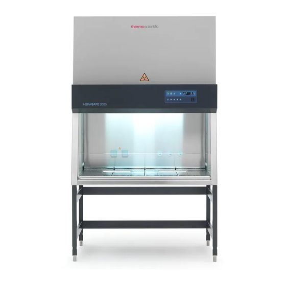
Unit Description Overall View Herasafe 2025: Figure 3 Overall View, Herasafe 2030i version Power supply cable [1]. Plenum assembly with plenum for downflow blower [4] and plenum for exhaust air blower [3]. The downflow filter and the exhaust air filter are installed directly to the pertaining blower. -
Page 22: Safety System
A steady airflow within the air system ensures that: a constant downflow allows the HEPA filters to remove contaminants so that the samples are always surrounded by ultrapure air, harmful particles are not carried over through the sample chamber (protection from cross-contamination). 50161258 HERAsafe 2025... - Page 23 If the warning system detects changes to one of these device functions, it issues: an audible and a visual alarm signal. Position monitoring The position sensors monitor the position of the front window; it will indicate when the front window is in the working position. HERAsafe 2025 50161258 | 23...
-
Page 24: Filter System
| Unit Description Chapter 4 Filter System Herasafe 2025 Figure 4 Filter System with Downflow Filter and Exhaust Air Filter The filter system consists of two HEPA filters [2] and [5] for the circulating air and for the exhaust air and a coarse filter for the aspired air. -
Page 25: Controls And Display
Foil keypad to control the equipment functions [2]. The status indicators of the display [2] indicate control operations initiated with the control elements. In the foil keypad the current status of the cabinet is shown. HERAsafe 2025 50161258 | 25... -
Page 26: Sample Chamber Access
C. It is generally needed for decontamination and introduction of larger accessories. NOTE Front cover lockout The front cover is equipped with a safety lockout and can only be open when the front window is completely closed. 50161258 HERAsafe 2025... -
Page 27: Figure 7 Access Through Front Window
The safety feature is backed up by a battery. Should a power failure occur, the auxiliary rocker switch (see “Using the auxiliary Rocker Switch” on page 52 ) can be used to lower the front window completely. HERAsafe 2025 50161258 | 27... -
Page 28: Device Interfaces
(shut-off valve, solenoid valve) must be installed. Use only laboratory safety burners in the sample chamber. External systems: Failure detection systems or gas supply solenoid valves may be connected to the safety cabinet control. 50161258 HERAsafe 2025... -
Page 29: Figure 9 Workspace Illumination
The workspace illumination [2], with fixing screws [1]is equipped with two LED [3] that are installed behind the light dome [4]. NOTE The reflector side (5) must be installed upwards, so that the radiation side (6) is fully active. HERAsafe 2025 50161258 | 29... -
Page 30: Uv Lamp Unit
The operating time of the UV lamps is preset and can be changed by the operator. NOTE Protection from UV radiation As a protection from harmful UV radiation, the UV lamps can only be activated if the front window is completely closed. 50161258 HERAsafe 2025... -
Page 31: Working Area
Unit Description | Chapter 4 Working Area The standard equipment comprises the segmented workplate for the Herasafe 2025. Special workplates are available as optional accessories. The workplates or workplate segments are placed onto the frame above the workspace drain pan. - Page 32 | Unit Description Chapter 4 50161258 HERAsafe 2025...
-
Page 33: Chapter 5 Start-Up
Prior to initial operation, the safety cabinet must be subjected to an installation test. Correct assembly and installation performed by the operator are essential for good start-up. Installing Unit and Accessories Herasafe 2025: Device without stand: Place the device without stand onto a sufficiently stable substructure so that the ... -
Page 34: Figure 12 Stand Installation
To assemble the (optional) stand and to install the device frame to the stand: Figure 12 Stand Installation 1. Slide the two crossmembers [2] onto the retaining angles [3] of the sidemembers [1]. Secure the crossmembers to the two sidemembers using the screws [4]. HERAsafe 2025 50161258... -
Page 35: Leveling The Device
4. Device with a stand: Place a bubble level onto the workplate and use the four levellers to effect a level state in all planes. When adjusting the device stand height, proceed from right to left and from rear to front. HERAsafe 2025 50161258 | 35... -
Page 36: Power Supply Connection
After the unit has been connected to the power supply system, the device control runs through a start-up initialization routine. USB-Port Figure 13 USB-Port The USB-Port on the top of the device is reserved for service work! HERAsafe 2025 50161258... -
Page 37: Installation Test
For operation in the work process, the sample chamber of the device and the accessories required for the work process must be disinfected and cleaned in accordance with the hygiene guidelines set forth for the application. HERAsafe 2025 50161258 | 37... - Page 38 | Start-up Chapter 5 HERAsafe 2025 50161258...
-
Page 39: Chapter 6 Operation
UV lamp is not installed, the function of this key is disabled). [12] Switch internal sockets on/off, the blue LED indicates that voltage is applied [13] Switch cabinet illumination on/off [14] Acknowledge audible Alarm [15] Switch unit on/off (switch off in Stand-By-Mode only) | 39 Herasafe 2025 50161258... -
Page 40: Display In Off-Mode
Fault cause ER 3 Pressure sensor 1 Downflow ER 4 Pressure sensor 2 Ehaust air ER 5 NVRAM - Error ER 6 BUS - Error ER 7 Switch error front window ER 8 BUS - Error Add-on PCB Herasafe 2025 50161258... -
Page 41: Description Of The Operating Modes
The air system blowers are switched on to ensure steady airflow: The green status indicator AIRFLOW STEADY is illuminated. The sample chamber illumination is available. The power supply for the sample chamber outlets is available: Herasafe 2025 50161258 | 41... - Page 42 The sample chamber illumination is available. The internal power supply in the sample chamber is available: If the internal power supply is ON, the blue status indicator INTERNAL POWER SUPPLY ACTIVATED is illuminated. Herasafe 2025 50161258...
-
Page 43: Operation
Lowering the front window: Keep lower side of the rocker switch depressed. Stopping the downward moving: Release rocker switch. Switching the device to OFF-Mode: Keep the key depressed until ready signal sounds. Herasafe 2025 50161258 | 43... -
Page 44: Moving The Front Window Into Working Position
3. If the movement starts above the working position, the front window must first be lowered below the working position and then be raised again. To lower the front window: Keep lower side of the rocker switch depressed. 4. Stop downward movement: Release rocker switch. Herasafe 2025 50161258... -
Page 45: Audible Warn Signal
This value refers to the set run time of the UV disinfection (optional). This display function is only available when the front window is not closed. The device must be switched to work mode (see Setting UV-Disinfektion). Herasafe 2025 50161258 | 45... -
Page 46: Switching The Cabinet To Off-Mode
The function switches to minute display (flashing). 5. Setting the minutes: Shortly press key or key 6. Scroll thru values: Depress key or key If the keys are depressed for approx. 2 or 3 seconds, a higher scroll speed is selected. Herasafe 2025 50161258... -
Page 47: Display Operating Hours Air Inflow
The device sensor system permanently monitors the circulating air velocity of the air flow in the sample chamber. The currently determined value (m/s) can only be called up in working mode. Display velocity value: Press key as often until LED is white illuminated. Herasafe 2025 50161258 | 47... -
Page 48: Setting Uv-Disinfection Time
3. Scroll thru the values in 30 minutes steps: Depress key or key 4. Store setting: Shortly press key If the setting is not stored, the disinfection time will be reset to the original value after approx. 15 seconds. Herasafe 2025 50161258... -
Page 49: Start Uv-Disinfection
2. The display shows the current time or operating hours, depending on what was previously selected. Rocker Switch Move front window upwards Move front window downwards Figure 15 Rocker switch With the rocker switch the front window can be moved upwards or downwards. Herasafe 2025 50161258 | 49... -
Page 50: Moving The Front Window
The audible warning is switched off when the front window is completely closed. 4. If the front window reaches the working position, the driving movement is automatically stopped: The status indicator is green illuminated. The audible warning is switched off. Herasafe 2025 50161258... -
Page 51: Chapter 7 Preparation
6. Then place samples into the chamber. 7. To interrupt the work process or for extensive experiment cycles without manual interference, switch the device to standby mode. When the working opening is completely closed, the safety cabinet is sealed aerosol-tight. | 51 HERAsafe 2025 50161258... -
Page 52: Response To Failure Messages
| Preparation Chapter 7 Response to Failure Messages Failure messages are displayed on the display as outlined in the section Error messages at page 40. If one of these messages is displayed, contact the Technical Service immediately. To isolate the cause of the failure, the operating personnel must perform only the following tests and measures: Check to see if the exhaust air opening on top of the cabinet is blocked. -
Page 53: Figure 16 Sitting Posture
After finishing an operation: Remove samples from the sample chamber and store them properly. Clean and disinfect the sample chamber surfaces, including the workplate and the drain pan. Clean and disinfect all accessories. HERAsafe 2025 50161258 | 53... - Page 54 | Preparation Chapter 7 50161258 HERAsafe 2025i...
-
Page 55: Chapter 8 Shut-Down
Shut-down Interrupting an Operation To interrupt a work process, the blowers can be switched off. 1. Remove all samples from the safety cabinet and store them properly. 2. Remove accessories from the sample chamber and clean and disinfect them. 3. Clean and disinfect the sample chamber surfaces, the workplate, and the drain pan. 4. - Page 56 | Shut-down Chapter 8 HERAsafe 2025 50161258...
-
Page 57: Chapter 9 Cleaning And Decontamination
when the device is shut down, when the device is discarded. Wipe/Spray Disinfection The wipe/spray disinfection is performed in three stages: predisinfection, cleaning, final disinfection. | 57 Herasafe 2025 50161258... - Page 58 3. Remove the cleaning liquid from the drain pan and wipe all sample chamber surfaces dry. Final disinfection: 1. Again, spray disinfectant on all sample chamber surfaces or wipe the surfaces clean with disinfectant. 2. Allow disinfectant to react as recommended by manufacturer. Herasafe 2025 50161258...
-
Page 59: Uv Disinfection After A Wipe/Spray Disinfection
25 % ammonium solution (10 ml per cubic meter of sample chamber volume). NOTE After the neutralization reaction time with ammonia, carry out check measurements and ventilate. Ventilation until the MAK value is reached: Formaldehyde concentration <0.3 ppm (Occupational Exposure Limits). Herasafe 2025 50161258 | 59... -
Page 60: Cleaning The Exterior Surfaces
4. Remove the cleaning liquid from the drain pan and wipe the drain pan surfaces thoroughly clean. NOTE Material residues After cleaning, make sure that all cleaning materials have been removed completely from the drain pan. 5. Reinstall the working plates. Herasafe 2025 50161258... -
Page 61: Replacing The Inlet Air Protection
6. Insert the workplate(s). NOTE Inlet air protection Do not operate the device without inlet air protection. Prior to any start-up of the device, make sure that the inlet air protection is installed! Herasafe 2025 50161258 | 61... - Page 62 | Cleaning and Decontamination Chapter 9 Herasafe 2025 50161258...
-
Page 63: Chapter 10 Maintenance
2. Rotate the lamp in the socket so that the lamp contacts can be removed from the groove in the socket. 3. Insert the new lamp into the socket and rotate until the contacts engage. 4. Push the cover onto the lamp casing. | 63 Herasafe 2025 50161258... -
Page 64: Sample Chamber Illumination
All retrofitting and repair work are interferences with the safety system of the unit. Particularly modifications to the filter system and resulting changes of the airflow may impair personal and material protection. Such work must be carried out only by authorized service personnel. 50161258 Herasafe 2025... -
Page 65: Chapter 11 Disposal
EMPP Front window, side windows Multi-layer safety glass Operating panel and indicator foil Polyethylene, Polyester Workplates Stainless steel UV bezels Stainless steel Armrests Stainless steel Rechargeable battery (safety fea- Nickel/metal hydrid ture: Lower Front Window) | 65 Herasafe 2025 50161258... - Page 66 Equipment (WEEE) Directive 2012/19/EU. It is marked with the following symbol: Thermo Electron has contracted with one or more recycling/disposal companies in each EU Member State, and this product should be disposed of or recycled through them. Further information on Thermo Fisher Scientific‘s compliance with these Directives. Herasafe 2025 50161258...
-
Page 67: Chapter 12 Technical Data
680/26.8 - 880/34.6 Unit height with stand mm/in 2216/87 / max. 2416/95 Side wall feed throughs Diameter mm/in 21.3/0.84 Distance lower edge mm/in 135/5.3 Distance from the rear wall Bushing 1 mm/in 153.5/6 Bushing 2 mm/in 243.5/9.6 | 67 Herasafe 2025 50161258... - Page 68 | Technical Data Chapter 12 Electrical Data Herasafe 2025 Voltage Rated voltage 230V - 1/N/PE AC - 50/60 Hz Blower voltage 48 V / DC Current Power consumption Leakage current < 3.5 IEC 1010, EN 61010 Motherboard fusing 2 x T15A H...
- Page 69 25/55 area module Max. load on overall kg/lbs 50/110 75/165 75/165 75/165 working area Airflow system Herasafe 2025 Air speeds Inflow m/s / fpm 0.45/88.6 Downflow m/s / fpm 0.32/63 Air volume Overall volume flow /h / cfm 910/536...
- Page 70 | Technical Data Chapter 12 Filter Herasafe 2025 Type HEPA (H 14 acc. DIN EN 1822) Material Glass fiber fleece Separability in MPPS 99.995 Separability at 0.3 μm 99.999 particle size Downflow Width mm/in 915/36 1220/48 1525/60 1830/72 Depth mm/in...
- Page 71 Technical Data | Chapter 12 Ambient conditions Herasafe 2025 Temperature Max. ambient tempera- °C / °F 40/104 ture during operation Min. ambient tempera- °C / °F 10/50 ture during operation Humidity Max. humidity/operation % h.r. Max. humidity/storage % h.r. Heat dissipation to environment 200 mm/8“...
- Page 72 | Technical Data Chapter 12 Herasafe 2025 50161258...
-
Page 73: Chapter 13 Device Log
Device Log Device type: Part number: Serial number: Service number: Location: Operator's note: Work carried out Notes Date Signature | 73 Herasafe 2025 50161258... - Page 74 | Device Log Chapter 13 Herasafe 2025 50161258...
-
Page 75: Chapter 14 Certificate Of Decontamination
Certificate of Decontamination | 75 Herasafe 2025 50161258... - Page 76 | Certificate of Decontamination Chapter 14 Herasafe 2025 50161258...
Need help?
Do you have a question about the HERASAFE 2025 and is the answer not in the manual?
Questions and answers