
Subscribe to Our Youtube Channel
Related Manuals for Vents VUT R 400 EH EC


Summary of Contents for Vents VUT R 400 EH EC
- Page 1 USER’S MANUAL VUT R 400 EH EC VUT R 700 EH EC VUT R 900 EH EC VUT R 1200 EH EC VUT R 1500 EH EC Heat recovery air handling unit...
-
Page 2: Table Of Contents
VUT R EH EC VUT R EH EC CONTENTS Safety requirements Introduction Delivery set Designation key Main technical data Design and operating logic Mounting and set-up Condensate drain Connection to power mains Unit control Maintenance Troubleshooting Storage and transportation rules Manufacturer's warranty Acceptance certifi cate Seller's information... -
Page 3: Safety Requirements
www.ventilation-system.com www.ventilation-system.com SAFETY REQUIREMENTS • Read the user’s manual carefully prior to the operation and installation of the heat recovery air handling unit, hereinafter the unit. • Installation and operation of the unit shall be performed in accordance with the present user’s manual as well as the provisions of all the applicable local and national construction, electrical and technical codes and standards. - Page 4 VUT R EH EC VUT R EH EC UNIT OPERATION SAFETY PRECAUTIONS Do not touch the controller or the remote Do not wash the unit with water. control with wet hands. Do not carry out the Protect the unit electric parts from water unit maintenance with wet hands.
-
Page 5: Introduction
This user’s manual includes technical description, operation, installation and mounting guidelines, technical data for the heat recovery air handling unit VENTS VUT R EH EC. The unit with a heat exchange and an electric heater is a heat recovery device and is one of the energy saving components used in buildings and premises. -
Page 6: Main Technical Data
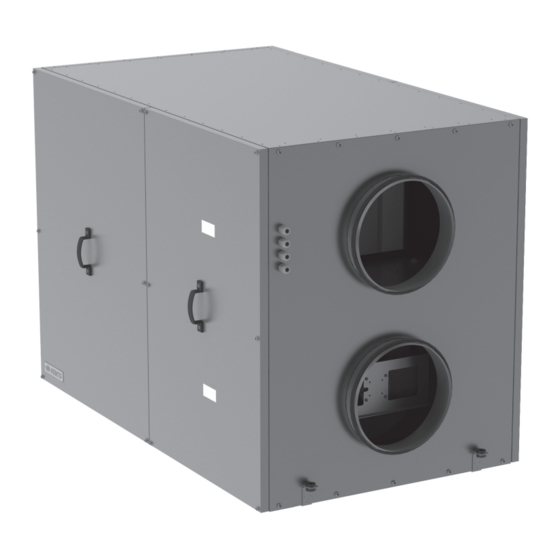
The unit design is regularly improved, so some models may slightly diff er from those ones described in this manual. UNIT OVERALL DIMENSIONS [MM] VUT R 400 EH EC, VUT R 700 EH EC, VUT R 900 EH EC VUT R 1200 EH EC, VUT R 1500 EH EC... - Page 7 www.ventilation-system.com www.ventilation-system.com UNIT TECHNICAL DATA VUT R VUT R VUT R VUT R VUT R Type 400 EH EC 700 EH EC 900 EH EC 1200 EH EC 1500 EH EC Unit supply voltage, 50 Hz [V] 1 ~ 230 1 ~ 230 3 ~ 380 3 ~ 380...
-
Page 8: Design And Operating Logic
VUT R EH EC VUT R EH EC DESIGN AND OPERATING LOGIC The unit has the following operating logic: Warm stale extract air from the room fl ows through the air ducts to the unit, where it is fi ltered, then air fl ows through the rotary heat exchanger and is exhausted outside by the extract fan through the air ducts. - Page 9 MINIMUM DISTANCES FOR ACCESSING TO THE UNIT UNIT А VUT R 400 EH EC 800 mm 60 mm VUT R 700 EH EC 900 mm SERVICE SIDE VUT R 900 EH EC 900 mm VUT R 1200 EH EC...
- Page 10 VUT R EH EC VUT R EH EC Precautions: The unit is designed for mounting on a rigid and stable structure considering the unit weight, Fig. 7. Make sure that a mounting construction has suffi cient load capacity for the unit weight. Otherwise reinforce an installation place by beams, etc.
-
Page 11: Condensate Drain
ALLOWED AND RESULT IN WARRANTY LOSS. The models VUT R 400 EH EC and VUT R 700 EH EC are rated for connection to single-phase AC 230 V / 50 Hz power mains. The models VUT R 900 EH EC, VUT R 1200 EH EC and VUT R 1500 EH EC are rated for connection to three-phase AC 400 V / 50 Hz power mains. - Page 12 VUT R EH EC VUT R EH EC EXTERNAL WIRING DIAGRAM FOR THE UNITS VUT R 900 EH EC, VUT R 1200 EH EC AND VUT R 1500 EH EC AI2 DI3 Cadet Mini-24 AIgnd AIgnd DI5 DO4 DO5 AI1 DI2 DIgnd AIgnd AIgnd...
- Page 13 ELECTRONIC CONTROL UNIT FOR THE UNITS FOR THE UNITS: FOR THE UNITS: • VUT R 400 EH EC • VUT R 900 EH EC • VUT R 700 EH EC • VUT R 1200 EH EC • VUT R 1500 EH EC 1 –...
- Page 14 VUT R EH EC VUT R EH EC The unit has the day and the night temperature mode. In each mode air temperature may be set and heated (Heating mode) or cooled down (Cooling mode): In the day mode any temperature is adjustable for heating or cooling. In the night mode the heating and cooling temperature values are static: Heating mode temperature is +25 °C.
- Page 15 www.ventilation-system.com www.ventilation-system.com Selecting the required function: Select the required function using the buttons then press Enter. Press Esc to return back to the list of functions. Modifying set point: Select a required parameter using the buttons and , then press Enter. Use the same buttons to edit a parameter, i.e. either to increase or decrease it .
- Page 16 VUT R EH EC VUT R EH EC Menu tree Factory setting Functions and parameters, eff ects V-06 Extract fan medium speed adjustment [%] V-07 Extract fan high speed adjustment [%] This parameter enables/disables fan start-up after power supply failure. Disable function (no) disables the fan V-08 Enables (yes) start-up after the power supply failure and enable function (yes) enables the fan start-up after the power supply...
-
Page 17: Unit Control
www.ventilation-system.com www.ventilation-system.com In case of any listed above alarm situations, except for the alarm U5 (overheating of the electric heater) the fans are stopped and the light indicator «Alarm» on controller display turns on. All the alarms are explained on the controller display. The automatic control system unblocks all the alarms automatically during the system restart (except for the alarm U5, overheating of the electric heater). -
Page 18: Maintenance
VUT R EH EC VUT R EH EC MAINTENANCE The unit must undergo technical maintenance 3 to 4 times a year. Maintenance includes general cleaning of the unit and the following operations: 1. Filter maintenance Contaminated fi lters increase air resistance thus impairing supply air delivery into the premises. The fi lters should be cleaned every 3-4 months. -
Page 19: Storage And Transportation Rules
www.ventilation-system.com www.ventilation-system.com STORAGE AND TRANSPORTATION RULES Store the unit in the manufacturer’s original packing box in a dry ventilated premise at the temperatures from +5 °C up to +40 °C. Storage environment must not contain aggressive vapours and chemical mixtures provoking corrosion, insulation and sealing deformation. -
Page 20: Acceptance Certificate
VUT R EH EC VUT R EH EC ACCEPTANCE CERTIFICATE Product Type Heat recovery air handling unit Model VUT R _____ EH EC Serial number Manufacturing date Is recognized as serviceable. The unit complies with the requirements according to the EU norms and directives, to the relevant EU-Low Voltage Equipment Directives, EU-Directives on Electromagnetic Compatibility. -
Page 21: Warranty Card
www.ventilation-system.com www.ventilation-system.com WARRANTY CARD Product type The heat recovery air handling unit Model VUT R ___ EH EC Serial number Manufacturing date Sales date Warranty period Sales company Seller’s seal ______________________________________________________________________________________________________ ______________________________________________________________________________________________________ ______________________________________________________________________________________________________ ______________________________________________________________________________________________________ ______________________________________________________________________________________________________ ______________________________________________________________________________________________________ ______________________________________________________________________________________________________ _________________________________________________________________________________________________... - Page 22 V76EN-02 2013...
Need help?
Do you have a question about the VUT R 400 EH EC and is the answer not in the manual?
Questions and answers