Table of Contents
Advertisement
Quick Links
Advertisement
Table of Contents

Related Manuals for Vents Enave-C 100 P Series


Summary of Contents for Vents Enave-C 100 P Series
- Page 1 USER'S MANUAL Enave-C 100 P A14 Enave-CT 100 P A14 Air handling unit...
-
Page 2: Table Of Contents
Enave-C(T) 100 P A14 CONTENTS Safety requirements ..................................3 Purpose ........................................ 5 Delivery set ......................................5 Designation key ....................................5 Technical data ....................................6 Design and operating principle ............................8 Mounting and set-up .................................. 10 Connection to power mains ..............................14 Technical maintenance ................................ -
Page 3: Safety Requirements
SAFETY REQUIREMENTS This unit is not intended for use by persons (including children) with reduced physical, sensory or mental capabilities, or lack of experience and knowledge, unless they have been given supervision or instruction concerning use of the unit by a person responsible for their safety. Children should be supervised to ensure that they do not play with the unit. - Page 4 Do not use the unit in a hazardous or explosive environment containing spirits, gasoline, insecticides, etc. Do not close or block the intake or extract vents in order to ensure the efficient air flow. Do not sit on the unit and do not put objects on it.
-
Page 5: Purpose
PURPOSE The unit is designed to ensure continuous mechanical air exchange in houses, offices, hotels, cafes, conference halls, and other utility and public spaces as well as to recover the heat energy contained in the air extracted from the premises to warm up the filtered stream of intake air. -
Page 6: Technical Data
Enave-C(T) 100 P A14 TECHNICAL DATA The unit is designed for indoor application with the ambient temperature ranging from +1 °C up to +40 °C and relative humidity up to 60 % without condensation. In cold, damp rooms, there is a possibility of freezing or condensation inside and outside the casing. In order to prevent condensation on the internal walls of the unit, it is necessary that the surface temperature of the casing is 2-3 °C above the dew point temperature of the transported air. - Page 7 Overall and connecting dimensions Ø 100* Ø 125* *The unit can be connected to a 100 mm or 125 mm air duct system. 100 mm air ducts are inserted into the connecting pipes, while 125 mm air ducts are put over the connecting pipes. www.ventilation-system.com...
-
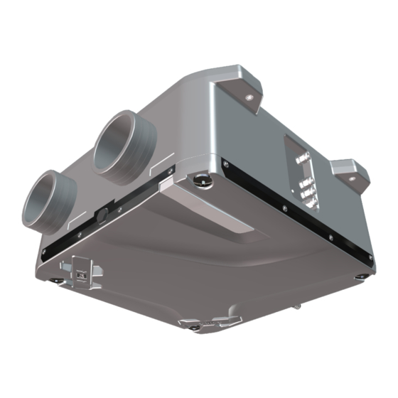
Page 8: Design And Operating Principle
Enave-C(T) 100 P A14 DESIGN AND OPERATING PRINCIPLE The unit is housed in a sound-insulated casing (item 1). The connecting pipes of the unit form a single structure with the unit casing. The function of the connecting pipes (item 7) is indicated on the stickers on the unit casing. The supply fan (item 10), exhaust fan (item 11) and heat exchanger (item 12) are also located inside the unit casing. - Page 9 VIEW FROM THE SERVICE SIDE WITH THE COVER REMOVED Enave-C(T) 100 P A14 R Intake air Extract air Exhaust air Supply air Enave-C(T) 100 P A14 L Supply air Exhaust air Extract air Intake air www.ventilation-system.com...
-
Page 10: Mounting And Set-Up
Enave-C(T) 100 P A14 MOUNTING AND SET-UP The units are fitted with connecting pipes for the connection of circular air ducts. 100 mm air ducts are inserted into the connecting pipes, while 125 mm air ducts are put over the connecting pipes. The unit is mounted in the ventilation system in accordance with the function of the connecting pipes. - Page 11 CHANGE OF THE UNIT MODIFICATION In some cases, it may be necessary to reconfigure the unit to ensure a more efficient placement of equipment and communications. To do this, it is necessary to rearrange the temperature and humidity sensors inside the casing as shown in the figure in the section "Unit design and operating principle".
- Page 12 Enave-C(T) 100 P A14 3. Mark the cable wires connected to the humidity sensor. Remember, photograph or write down the connection points of cables. 4. Pull the cable out to the opposite side of the unit casing. Remove it from the channel.
- Page 13 Diagram of connecting the motor control cables to the controller board after moving Motor control cable M2 Motor control cable M1 Controller board A1.1 Condensate drainage Condensate drainage is required in systems with heat recovery. WARNING! The drain pipe on the outdoor air supply side is intended for the removal of condensate, which forms during cooling of the supply air in the heat exchanger when the unit operates in a warm, humid climate conditions.
-
Page 14: Connection To Power Mains
Enave-C(T) 100 P A14 CONNECTION TO POWER MAINS The connection must be made using durable, insulated and heat-resistant conductors (cables, wires). The external power input must be equipped with an automatic circuit breaker built into the stationary wiring to open the circuit in the event of overload or short-circuit. -
Page 15: Technical Maintenance
TECHNICAL MAINTENANCE Maintenance operations of the unit are required 3-4 times per year. They include general cleaning of the unit and the following operations: 1. Filter maintenance (3-4 times per year). Dirty filters increase air flow resistance, which leads to a decrease in the supply of supply air to the room and creates preconditions for occurrence of faults. - Page 16 Enave-C(T) 100 P A14 3. Fan maintenance (once per year). Even in case of regular maintenance of the filters, some dust may accumulate inside the fans and reduce the fan performance and supply air flow. Clean the fans with a soft cloth, brush, or using compressed air. Do not use water, aggressive solvents, or sharp objects as they may damage the impeller.
-
Page 17: Troubleshooting
TROUBLESHOOTING Problem Possible reasons Troubleshooting Make sure the power supply line is connected No power supply. correctly, otherwise troubleshoot a connection error. Disconnect the fan from power supply. Jammed motor. Troubleshoot the motor jamming. The unit does not start. Restart the unit. Disconnect the fan from power supply. -
Page 18: Manufacturer's Warranty
Enave-C(T) 100 P A14 MANUFACTURER’S WARRANTY The product is in compliance with EU norms and standards on low voltage guidelines and electromagnetic compatibility. We hereby declare that the product complies with the provisions of Electromagnetic Compatibility (EMC) Directive 2014/30/EU of the European Parliament and of the Council, Low Voltage Directive (LVD) 2014/35/EU of the European Parliament and of the Council and CE-marking Council Directive 93/68/EEC. -
Page 19: Certificate Of Acceptance
CERTIFICATE OF ACCEPTANCE Unit Type Air handling unit Model Serial Number Manufacture Date Quality Inspector’s Stamp SELLER INFORMATION Seller Address Phone Number E-mail Purchase Date This is to certify acceptance of the complete unit delivery with the user’s manual. The warranty terms are acknowledged and accepted. - Page 20 V224EN-01...
Need help?
Do you have a question about the Enave-C 100 P Series and is the answer not in the manual?
Questions and answers