Table of Contents
Advertisement
USER'S MANUAL
• VUT R 400 TN H EC A17
• VUT R 700 TN H EC A17
• VUT R 900 TN H EC A17
• VUT R 400 TN EH EC A17
• VUT R 700 TN EH EC A17
• VUT R 900 TN EH EC A17
• VUT R 400 TN H EC A18
• VUT R 700 TN H EC A18
• VUT R 900 TN H EC A18
• VUT R 400 TN EH EC A18
• VUT R 700 TN EH EC A18
• VUT R 900 TN EH EC A18
Heat recovery air
handling unit equipped
with a heat pump
Advertisement
Table of Contents

Subscribe to Our Youtube Channel
Related Manuals for Vents VUT R 400 TN H EC A17


Summary of Contents for Vents VUT R 400 TN H EC A17
- Page 1 USER’S MANUAL • VUT R 400 TN H EC A17 • VUT R 700 TN H EC A17 • VUT R 900 TN H EC A17 • VUT R 400 TN EH EC A17 • VUT R 700 TN EH EC A17 •...
-
Page 2: Table Of Contents
www.ventilation-system.com CONTENTS Safety requirements ....................3 Introduction ......................5 Purpose ........................5 Delivery set ........................ 5 Designation key ....................... 5 Technical data ......................6 Unit design and operating logic ................ 8 Mounting and set-up ..................... 10 Connection to power mains ................14 Unit control ........................ -
Page 3: Safety Requirements
SAFETY REQUIREMENTS • Read the user’s manual carefully prior to installing and operating the air handling unit (hereinafter referred to as «the unit»). • Fulfil the user’s manual requirements as well as the provisions of all the applicable local and national construction, electrical and technical norms and standards. - Page 4 www.ventilation-system.com Do not touch the unit controls with wet hands. Do not wash the unit with water. Protect the Do not carry out the maintenance operations electric parts of the unit against ingress of water. with wet hands. Use the unit only for its intended purpose. Do not put any water containers on the unit, i.e.
-
Page 5: Introduction
INTRODUCTION This user’s manual includes technical description, operation, installation and mounting guidelines, technical data for the VUT R TN (E)H EC heat recovery air handling unit, hereinafter referred to as «the unit». PURPOSE The unit is designed to ensure continuous mechanical air exchange in houses, offices, hotels, cafés, conference halls, and other utility and public spaces as well as to recover the heat energy contained in the air extracted from the premises to warm up the filtered stream of supply air. -
Page 6: Technical Data
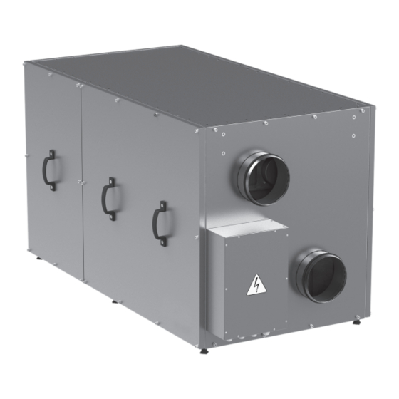
www.ventilation-system.com TECHNICAL DATA The unit is designed for indoor application with the ambient temperature ranging from +1 °C up to +40 °C and relative humidity up to 80 %. In order to prevent condensation on the internal walls of the units, it is necessary that the surface temperature of the casing is 2-3 °C higher than the dew point temperature of the transported air. - Page 7 OVERALL DIMENSIONS OF THE UNIT, MM VUT R 400 TN (E)H EC 1421 1250 Ø 160 VUT R 700 TN (E)H EC AND VUT R 900 TN (E)H EC 1667 1551 Ø 250...
-
Page 8: Unit Design And Operating Logic
www.ventilation-system.com UNIT DESIGN AND OPERATING LOGIC The unit has the following operating logic: Warm stale extract air from the room flows to the unit, where it is filtered by the supply filter. Then the air is moved through the rotary heat exchanger, then through the condenser/evaporator of the heat pump and is exhausted outside with the exhaust fan. - Page 9 VUT R 400 TN (E)H EC unit design and operating principle (service side view) Heat-transfer unit Drain pan Rotary heat exchanger Supply fan Electric heater Control unit (VUT R 400 TN EH EC models only) Intake lter INTAKE AIR SUPPLY AIR EXHAUST AIR EXTRACT AIR Exhaust fan...
-
Page 10: Mounting And Set-Up
www.ventilation-system.com MOUNTING AND SET-UP READ THE USER’S MANUAL PRIOR TO MOUNTING THE UNIT. Ensure adequate access to the unit for maintenance and repair. The minimum required clearances between the unit and the adjoining walls are given in the figure below. Minimum straight air duct length: - equal to 1 air duct diameter on intake side - equal to 3 air duct diameters on outlet side... - Page 11 INSTALLATION ON HORIZONTAL SURFACE SAFETY PRECAUTIONS The unit must be mounted to a rigid and stable structure. The unit must be suspended using anchor bolts. Make sure that the base structure is capable of sustaining the unit weight. Otherwise reinforce the mounting location with beams or similar elements.
- Page 12 www.ventilation-system.com Th-Tune CONTROL PANEL INSTALLATION To install the rear part of the control panel use a suitable mounting box (minimum diameter 65 mm and minimum depth 31 mm). 1. Use a screwdriver to pull the front and the rear sides of the control 2.
- Page 13 pGD1 CONTROL PANEL INSTALLATION Connect the pGD1 control panel to the controller connector (see the figure on page 15) using the 6P6C (PLUG-6P6C-P-C2) phone plug. The maximum length of the phone cable is 50 m. To mount the control panel on a wall route the phone cable to the selected location. 1.
-
Page 14: Connection To Power Mains
www.ventilation-system.com CONNECTION TO POWER MAINS DISCONNECT THE UNIT FROM POWER MAINS PRIOR TO ANY OPERATIONS. CONNECTION OF THE UNIT TO POWER MAINS IS ALLOWED BY A QUALIFIED ELECTRICIAN WITH A WORK PERMIT FOR THE ELECTRIC UNITS UP TO 1000 V AFTER CAREFUL READING OF THE PRESENT USER’S MANUAL. -
Page 15: Unit Control
UNIT CONTROL The unit is equipped with a built-in automatic control system and a control panel. Control unit VUT R 700 TN EH EC / VUT R 900 TN EH EC of VUT R 400 TN EH EC control unit pGD1 control panel pGD1 control panel connector... - Page 16 www.ventilation-system.com The «Auto» speed becomes available upon entering the Humidity Sensor Feedback mode enabling the unit to increase the air exchange rate automatically at an increase of the relative humidity (CO2) level in the served air space. ATTENTION!!! This option is only available with the th-Tune control panel in a special configuration, the external humidity or CO2 control sensor with a 0-10 V output signal to be purchased separately.
- Page 17 Connect the pGD1 control panel to the controller connector (see figure on page 13) using the 6P6C (PLUG- 6P6C-P-C2) phone plug. The maximum length of the phone cable is 50 m. The pGD1 offers extended functionality and has identical settings entered via the controller screen (see «Controller functions and menu»).
- Page 18 www.ventilation-system.com CONTROLLER FUNCTIONS AND MENU The controller has the following controls and indicators: Backlit LCD display. The display screen shows the current parameters of the system operation, temperature values, pre-set parameters and alarms. Control buttons of the automatic control system: Enter Enters speci c modes: editing a parameter, saving an edited parameter and function list navigation...
- Page 19 To modify the unit operation parameters move the cursor to the required line using the button. Then use the buttons to set the desired value and then press the to confirm. To exit the parameter change mode without VIEWING THE READINGS FROM THE TEMPERATURE SENSORS, THE HUMIDITY AND СО SENSORS.
- Page 20 www.ventilation-system.com 3. Heating — the fans, the heat exchanger and the heat pump are 4. Cooling — the fans, the heat exchanger and the heat pump are enabled. The user may change the temperature and speed settings. enabled. The temperature and speed settings are available. While While in the Heating mode the unit operates only to the effect of in this mode the unit operates only to the effect of decreasing the increasing the indoor temperature up to the pre-set value.
- Page 21 UNIT PARAMETERS To enter the user parameter menu press the button. Use the buttons to select the desired menu item and press the button to enter. 1. System information Page 1/3 contains the following parameters: To view the system information enter the user parameter menu and select «System info».
- Page 22 www.ventilation-system.com Schedule setup 1. Day selection. 2. Setting the schedule recording start time. Use the button to select the «Day» parameter and then use the Press the button to start setting the first entry. Then use the buttons to select the day for setting the schedule. buttons to set the start time for the first entry in hours.
- Page 23 Setting up exception periods Page 2/4 Exception period setting. While in the Scheduled operation mode you may need to create a To select a parameter press the button. period of operation to a different set of scheduled settings between Then use the buttons to set the desired value.
- Page 24 www.ventilation-system.com Setting up setpoints Page 4/4 The setpoints for schedule entries are programmed on page 4/4. Setting up setpoints. Press the button to select a parameter. Then use the buttons to set the desired parameter value. You may program up to three entries. Set the fan speed and temperature for each setpoint. UNIT PARAMETER SETUP Page 1/04.
- Page 25 Page 4/04. Hour meter operation. If the unit is equipped with a recirculation damper the mode can be set to either Auto or Manual. If the manual mode is selected, set the necessary damper opening angle (30 % by factory default). On elapsing of the filter replacement interval (3,000 hours by default) the system will generate a filter replacement alert.
-
Page 26: Technical Maintenance
www.ventilation-system.com TECHNICAL MAINTENANCE DISCONNECT THE UNIT FROM POWER MAINS PRIOR TO ANY MAINTENANCE OPERATIONS WITH THE UNIT. Maintenance operations of the unit are required 3-4 times per year. Maintenance includes general cleaning of the unit and the following operations: Filter maintenance: Dirty filters increase air resistance in the system and reduce supply air volume. -
Page 27: Troubleshooting
To clean the heat-transfer unites remove the heat exchanger from the unit and blow the heat-transfer unites with compressed air or use a vacuum cleaner. After cleaning re-install the heat exchanger into the unit. Fan maintenance (once per year). Even in case of regular maintenance of the filters, some dust may accumulate inside the fans and reduce the fan performance and supply air flow. -
Page 28: Manufacturer's Warranty
www.ventilation-system.com THE UNIT MAY NOT BE INCLINED MORE THAN 45 DEGREES IN RELATION TO HORIZON. Follow the applicable moving regulations specific to the particular cargo type while loading and unloading. The unit can be transported in the original packing by any mode of transport without limitation provided proper protection against precipitation and mechanical damage. -
Page 29: Acceptance Certificate
ACCEPTANCE CERTIFICATE Unit Type Припливно-витяжна установка з рекуперацією тепла Model ВУТ Р ____________ ТН (Е)Г ЕС Serial Number Manufacture Date We hereby declare that the product complies with the essential protection requirements of Electromagnetic Council Directive 2004/108/EC, 89/336/EEC and Low Voltage Directive 2006/95/EC, 73/23/EEC and CE-marking Directive 93/68/EEC on the approximation of the laws of the Member States relating to electromagnetic compatibility. -
Page 30: Warranty Card
www.ventilation-system.com WARRANTY CARD Unit Type Heat recovery air handling unit Model VUT R ________ TN (E)H EC Serial Number Manufacture Date Purchase Date Warranty Period Seller Seller’s Stamp ___________________________________________________________________________________________________________ ___________________________________________________________________________________________________________ ___________________________________________________________________________________________________________ ___________________________________________________________________________________________________________ ___________________________________________________________________________________________________________ ___________________________________________________________________________________________________________ ___________________________________________________________________________________________________________ ______________________________________________________________________________________________________... - Page 32 V107EN-02...
Need help?
Do you have a question about the VUT R 400 TN H EC A17 and is the answer not in the manual?
Questions and answers