
Related Manuals for Vents VUTR 400 V EC


Summary of Contents for Vents VUTR 400 V EC
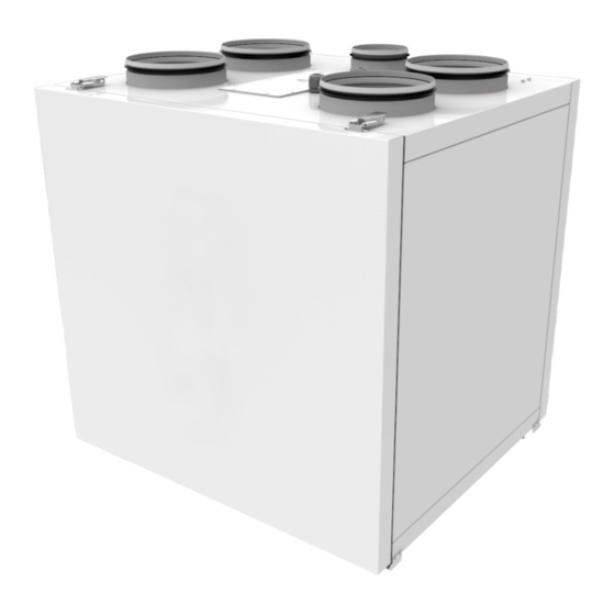
- Page 1 USER’S MANUAL VUTR 400 V EC VUTR 400 VE EC VUTR 600 V EC VUTR 600 VE EC Heat recovery air handling unit...
-
Page 2: Table Of Contents
VUTR 400 (600) V(E) EC CONTENTS Safety requirements ..................................2 Purpose ........................................ 4 Delivery set ......................................4 Designation key ....................................4 Technical data ....................................5 Design and operating principle ............................6 Connection to power mains ..............................10 Technical maintenance ................................12 Storage and transportation regulations .......................... - Page 3 • Do not change the power cable length at your own discretion. Do not bend the • Do not lay the power cable of the unit in power cable. Avoid damaging the power close proximity to heating equipment. cable. Do not put any foreign objects on the power cable.
-
Page 4: Purpose
VUTR 400 (600) V(E) EC PURPOSE The unit is designed to ensure continuous mechanical air exchange in houses, offices, hotels, cafes, conference halls, and other utility and public spaces as well as to recover the heat energy contained in the air extracted from the premises to warm up the filtered stream of intake air. -
Page 5: Technical Data
Dimensions [mm] Model VUTR 400 V(E) EC VUTR 600 V(E) EC TECHNICAL DATA MODEL VUTR 400 V EC VUTR 400 VE EC VUTR 600 V EC VUTR 600 VE EC Unit voltage [V/50 (60) Hz] ~1-230 Maximum unit power (without a heater) [W]... -
Page 6: Design And Operating Principle
VUTR 400 (600) V(E) EC DESIGN AND OPERATING PRINCIPLE The unit has the following operating principle: Warm stale extract air from the room flows to the unit where it is filtered. Then the air is moved through the rotary heat exchanger and is exhausted outside with the exhaust fan. - Page 7 MOUNTING AND SET-UP READ THE USER'S MANUAL BEFORE INSTALLING THE UNIT. THE UNIT MUST BE MOUNTED ON A PLANE SURFACE. MOUNTING OF THE UNIT TO AN UNEVEN SURFACE CAN LEAD TO THE UNIT CASING DISTORTION AND OPERATION DISTURBANCE. While mounting the unit provide enough access for maintenance or repair work. The minimum recommended clearances between the unit and the adjoining walls are given in the figure below.
- Page 8 VUTR 400 (600) V(E) EC UNIT WALL MOUNTING 1. Attach the wall mounting bracket to the wall using dowels with screws (not included in the delivery set). Attach the wall mounting bracket to the wall considering the wall material and the unit weight. 2.
- Page 9 SERVICE SIDE CHANGE 1. Make sure of the correct unit service side selection. Unit mounting position should enable free excess to the service panel for maintenance and service operations. Extract air Intake air Air from the exhaust hood Supply air Exhaust air Exhaust air Supply air...
-
Page 10: Connection To Power Mains
VUTR 400 (600) V(E) EC CONNECTION TO POWER MAINS POWER OFF THE POWER SUPPLY PRIOR TO ANY OPERATIONS WITH THE UNIT. THE UNIT MUST BE CONNECTED TO POWER SUPPLY BY A QUALIFIED ELECTRICIAN. THE RATED ELECTRICAL PARAMETERS OF THE UNIT ARE GIVEN ON THE MANUFACTURER’S LABEL. - Page 11 Design Name Model Wire*** SM1* Exhaust or supply air damper electric actuator LF230 2x0.75 mm SM2* Exhaust or supply air damper electric actuator LF230 2x0.75 mm PK1* Contact from fire alarm panel 2x0.75 mm P1** Remote control panel th-Tune 5x0.25 mm Kitchen hood *The appliances are not supplied with the unit, are available on the separate order.
-
Page 12: Technical Maintenance
VUTR 400 (600) V(E) EC TECHNICAL MAINTENANCE DISCONNECT THE UNIT FROM POWER SUPPLY BEFORE ANY MAINTENANCE OPERATIONS! Maintenance operations of the unit are required 3-4 times per year. They include general cleaning of the unit and the following operations: 1. Filter maintenance. Dirty filters increase air resistance in the system and reduce supply air volume. -
Page 13: Storage And Transportation Regulations
POSSIBLE REASONS AND TROUBLESHOOTING Problem Possible reasons Troubleshooting Make sure the power supply line is connected correctly, otherwise No power supply. troubleshoot a connection error. Turn the unit off. Troubleshoot the motor jam and the impeller clogging. Clean The motor is jammed, the impeller blades are soiled. The fan(s) does not start when the blades. -
Page 14: Manufacturer's Warranty
VUTR 400 (600) V(E) EC MANUFACTURER’S WARRANTY The product is in compliance with EU norms and standards on low voltage guidelines and electromagnetic compatibility. We hereby declare that the product complies with the provisions of Electromagnetic Council Directive 2014/30/EU, Low Voltage Directive 2014/35/ EU and CE-marking Directive 93/68/EEC. -
Page 15: Certificate Of Acceptance
CERTIFICATE OF ACCEPTANCE Unit Type Heat recovery air handling unit Model VUTR____________V__EC_______ Serial Number Manufacture Date Quality Inspector’s Stamp SELLER INFORMATION Seller Address Phone Number E-mail Purchase Date This is to certify acceptance of the complete unit delivery with the user’s manual. The warranty terms are acknowledged and accepted. - Page 16 V140EN-04...
Need help?
Do you have a question about the VUTR 400 V EC and is the answer not in the manual?
Questions and answers