Subscribe to Our Youtube Channel
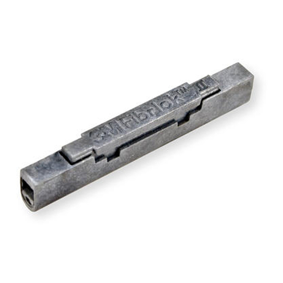
Summary of Contents for 3M Fibrlok II
- Page 1 Fibrlok II Angle Fiber Splice 2529-AS ™ ™ Fibrlok 250 µm Angle Fiber Splice 2540-AS ™ ™ Instructions January 2009 78-8140-1580-2-C...
- Page 2 Upon eye contact, immediately flush eyes with water while holding eyelids open and continue flushing for ten minutes. Contact a physician. Upon skin contact, wash with soap and water. Product Information: Material Safety Data Sheet or 3M Company, St. Paul MN, 55144-1000, (651) 733-1110 Operator 55 Bare Fiber Handling cCAUTION Cleaved glass fibers are sharp and can pierce the skin.
- Page 3 Sections 5 and 6 are specifically for Fibrlok II 2529-AS. Section 5 relates to the repositioning of the fiber if a high splice loss is seen. This is possible only using Fibrlok II 2529-AS.
- Page 4 Place splice in the tool with the included in the 3M Fiber Optic Angle Cleave ™ Fibrlok cap up.
- Page 5 For 900 µm buffer fiber, cut the buffer. If the 900 µm To verify the correct strip length, use the white marks slides easily from the fiber it is loose tube or semi- on the left side of the cleaver. Align the coating edge tight buffered fiber.
- Page 6 Place fiber in angle cleaver so that the coating edge is 3.11 For 250 µm fiber and tight buffer 900 µm fiber, the fiber at 12.5 ± 0.5 mm. should be placed in the fiber holder tool groove which is labeled “Tight buffer”.
- Page 7 Open cleaver clamp #1 and remove fiber holder and fiber from cleaver. Note: Do not open activation lever after cleaving until fiber holder and fiber have been removed. Place the fiber holder into the assembly tool base and push the holder to 3M ™ Fibrlok ™ Splice opening.
- Page 8 Do not attempt to “tune” or optimize the splice first fiber and pushes the first fiber slightly back out as this may result in higher splice loss. The 3M ™ of the splice.
- Page 9 Place the two fiber holders into Fibrlok assembly tool base and open the guide funnel, middle covers and the back clamp on the fiber holder. While the splice is in the splice holding cradle, insert the short prongs of the 3M Fibrlok II Splice cap ™...
- Page 10 Carefully lay the splice on top of the holder without securing the splice into the holder. Note: If there is difficulty using the cap lifter, a second cap lifter is packaged with the 3M ™ Fibrlok Angle Splice Assembly Tool 2501-AS ™...
- Page 11 For 250 to 900 µm splices: a. Store the 900 µm fiber first. b. Grasping the splice by the 900 µm fiber, observe how the splice lays in its relaxed state. Rotate the splice through the smallest possible angle to install it in the tray.
- Page 12 Warranty; Limited Remedy; Limited Liability. This product will be free from defects in material and manufacture for a period of one (1) year from the time of purchase. 3M MAKES NO OTHER WARRANTIES INCLUDING, BUT NOT LIMITED TO, ANY IMPLIED WARRANTY OF MERCHANTABILITY OR FITNESS FOR A PARTICULAR PURPOSE. If this product is defective within the warranty period stated above, your exclusive remedy shall be, at 3M’s option, to replace or repair the 3M product or refund the purchase price of the 3M product.


Need help?
Do you have a question about the Fibrlok II and is the answer not in the manual?
Questions and answers