Wood-mizer BMT200 Safety, Operation, Maintenance & Parts Manual
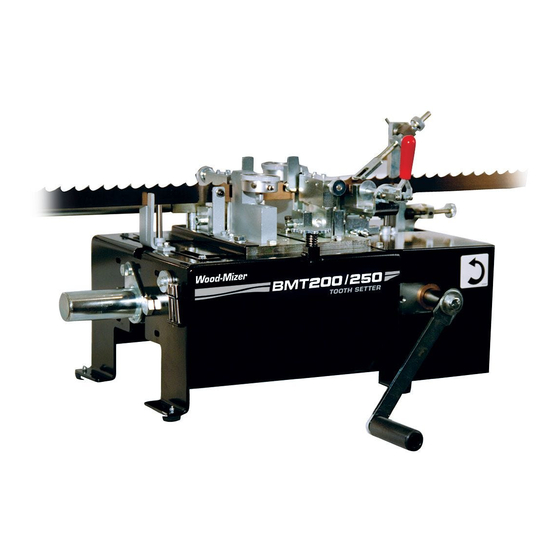
Dual toothsetter
Hide thumbs
Also See for BMT200:
- Safety, operation, maintenance & parts manual (74 pages) ,
- Quick start manual (19 pages) ,
- Safety, operation, maintenance & parts manual (79 pages)
Table of Contents
Advertisement
Quick Links
Advertisement
Table of Contents

Related Manuals for Wood-mizer BMT200


Summary of Contents for Wood-mizer BMT200
- Page 1 Dual Toothsetter Safety, Operation, Maintenance & Parts Manual BMT200 Rev. A.02 BMT250 Rev. A.02 Safety is our #1 concern! Read and understand all safety information and instructions before oper- ating, setting up or maintaining this machine. Form #1792...
- Page 2 Active Patents assigned to Wood-Mizer, LLC Wood-Mizer, LLC has received patents that protect our inventions which are a result of a dedication t o research, innovation, development, and design. Learn more at: woodmizer.com/patents ©2021 Wood-Mizer LLC Printed in the United States of America, all rights reserved. No part of this manual may be reproduced in any form by...
-
Page 3: Table Of Contents
Table of Contents Section-Page SECTION 1 INTRODUCTION About This Manual....................1-1 Getting Service ......................1-1 Specifications ......................1-1 Dimensions and Specifications.................. 1-1 SECTION 1 GENERAL SAFETY Safety Symbols......................2-1 Safety Instructions ..................... 2-1 Observe ALL Safety Instructions............2-1 Electrical Lockout Procedures................... 2-1 SECTION 2 SETUP &... - Page 4 Table of Contents Section-Page SECTION 3 REPLACEMENT PARTS Dual Toothsetter (Complete) ..................3-1 Dual Toothsetter Assembly ..................3-2 Base Housing Assembly.................... 3-3 Feed Drive Assembly ....................3-5 Blade Setters......................3-7 Blade Set Arm Assembly ..................3-9 Clamp Assembly ..................... 3-11 Index Assembly .......................
-
Page 5: Introduction
SECTION 1 INTRODUCTION About This Manual ® This manual replaces any previous information received on your Wood-Mizer equipment. The information and instructions in this manual do not amend or extend the limited warranties for the equipment given at the time of purchase. - Page 6 Introduction Dimensions and Specifications The maximum electrical loads are listed below. Model Maximum Load BMT250 (1 x 110V AC 60Hz) 6.8 Amps BMT250 (1 x 220V AC 50/60Hz) 3.95 Amps DANGER! Make sure all electrical installation, service and/or maintenance work is performed by a qualified electrician and is in accordance with applicable electrical codes.
-
Page 7: General Safety
If replacing a component that has a safety decal ANSI, OSHA, or locally required safety procedures. It is the affixed to it, ensure the new component also has the owner/operator’s responsibility and not Wood-Mizer LLC safety decal affixed. to ensure all operators are properly trained and informed of all safety protocols. - Page 8 General Safety Electrical Lockout Procedures Amputation of the energy, and shall know the methods to control the Burn energy. Shock If the machine or equipment is operating, shut it down by the normal stopping procedure (depress the stop button, open TO CONTROL MAINTENANCE DANGERS: switch, close valve, etc.).
-
Page 9: Setup & Operation
Setup & Operation Assembly SECTION 2 SETUP & OPERATION Assembly Place the setter on a table or workbench sturdy enough to support the weight of the machine. Be sure there is enough room on either side of the setter to allow for the blade to travel. - Page 10 Setup & Operation Assembly See Figure 2-2. Thread a blade support tube into the threaded holes in the three mount- ing blocks. Assemble a blade support extension tube to each blade support tube. NOTE: If installing the optional arm kit for heavier blades, assemble the blade support extension tubes to the extended mounting arms.
-
Page 11: Auto Feed Installation (Optional - Ac Only)
Setup & Operation Assembly Auto Feed Installation (Optional - AC Only) The AC Auto Feed Option includes an electric motor and control to automate the setting process. See Figure 2-3. Before installing the Auto Feed, remove the manual feed crank handle. Disassemble the bolt, lock washer and fender washer to remove the handle. - Page 12 Setup & Operation Assembly See Figure 2-4. Install two 5 x 5 x 25mm round end keys to the feed shaft and slide the motor with the mount plate onto the feed shaft. Secure the motor to the setter base. M8 Hex Nylon Nut (4) 5 x 5 x 25mm Round End Key (2)
-
Page 13: Auto Feed Installation (Optional - Dc Only)
Setup & Operation Assembly or modify the power cord to match your receptacle. DANGER! For the user's safety, the power cord on this product has a grounded plug. This power cord should only be used with correctly grounded (3-hole) receptacles to avoid electrical shock. - Page 14 Setup & Operation Assembly hex head bolt and split lock washer to reinstall the shaft cover over the manual feed shaft. M10-1.25 x 20 Remove bolt, hex head bolt and lock washer, split lock washer fender washer and crank handle Remove Shaft Cover Remove cover DS0001-16...
- Page 15 Setup & Operation Assembly See Figure 2-7. Remove the existing shaft end bolts from the setter. Install the feed motor mount bracket around the feed shaft and secure with the provided shaft end bolts, flat washers and existing nylon lock nuts. Leave the bolts slightly loose until the motor is pinned to the feed shaft as described later.
- Page 16 Setup & Operation Assembly See Figure 2-9. Slide the sleeve and motor assembly onto the feed shaft and secure to the motor mount bracket with four flat washers, lock washers, hex head bolts and self-locking nuts. Leave the bolts slightly loose until the motor is pinned to the feed shaft as described later.
- Page 17 Setup & Operation Assembly See Figure 2-11. Set the Auto Feed control box near the setter at a convenient operating location. Connect the motor harnesses with two-pin connectors together. Secure the motor harness with wire ties as necessary. Motor Harness DS0013-2B Sensor Ground Wire...
-
Page 18: Dual Setter Calibration
For calibration and alignment videos, refer to your DVD shipped with this manual, or look online at https://www.youtube.com/watch?v=eHWjGntODr8&ab_channel=Wood-Mizer Tooth Set Master Gauge Calibration The tooth set gauge accurately measures the set of any blade tooth. The gauge needs to be assembled and calibrated before use. - Page 19 Dual Setter Calibration Loop the blade over the setter and position between the posts of the blade support guides. Place the blade between the clamp rollers and between the setter blocks, resting on the blade height adjustment pins. Advance setter to open setter assemblies Pull clamp handle open...
- Page 20 Dual Setter Calibration See Figure 1-16. Place the set master gauge around the blade to measure tooth set. Turn the lock knob counterclockwise to loosen and adjust the blade height rest pin up or down. Adjust so when the blade rests on the pin, the gullet of the blade is just below the clamp plate.
- Page 21 Dual Setter Calibration See Figure 1-20. Turn the clamp knob clockwise to securely clamp the blade and read the set measurement displayed by the set master gauge. Note the tooth set measurement and mark the measured tooth with a marker. Read set Tooth set back toward gauge...
- Page 22 Dual Setter Calibration NOTE: The setter is factory-set for blades with 7/8" tooth spacing. Once a rear-set tooth is indexed in front of the right setter block, a forward-set tooth should be positioned in front of the left setter block. To adjust the setter for different tooth spacing, loosen the left setter mounting bolts and slide the assembly to position the setter block behind a forward-set tooth.
- Page 23 Dual Setter Calibration See Figure 1-26. Unlock the dial lock and adjust the setter gauge bezels so the needles of the setter gauges show the same tooth set measurements taken previously with the set master gauge. Setter Gauge Bezel Dial Lock DS0001-38 FIG.
-
Page 24: Operation
Operation Operation Blade Installation/Setup WARNING! Always wear gloves and eye protection when handling bandsaw blades. Changing blades is safest when done by one person! Keep all other persons away from area when coiling, carrying or changing a blade. Failure to do so may result in serious injury. - Page 25 Control Box Rear FIG. 1-29 DC ONLY NOTE: Most blades manufactured by Wood-Mizer are made so the set pattern across the weld is consistent with the rest of the blade. You should mark your blade for the starting point or start at the weld.
- Page 26 Operation Pull the blade clamp lever open and flip the index arm up. Turn the feed handle counter- clockwise (or push and hold the Auto Feed option START - JOG button) to advance the setter until the setter assemblies open. WARNING! Before installing the blade, inspect it for dam- age and cracks.
- Page 27 Operation Loosen the wing nut on each blade support guide and adjust so the blade is positioned between the support posts. Tilt the guide slightly forward in the direction the blade travels and retighten the wing nut. IMPORTANT! Make sure the blade support does not lift the blade.
- Page 28 Operation See Figure 1-32. Blade Height Adjustment Pin Blade Height Blade Height Adjustment Pin Adjustment Knob Setter Gauge Bezel Dial Lock DS0001-25B Gullet Even with Clamp Plate FIG. 1-32 Turn the feed handle counterclockwise (or push and hold the AUTO FEED option START - JOG button) to advance the setter until the index arm fully extends, pushing the blade forward.
- Page 29 Operation See Figure 1-33. Index arm adjustment knobs Adjust left setter for tooth spacing Index arm backstop Left setter adjustment knob mounting bolt (2) DS0001-26 Rear-set tooth just to the right of center FIG. 1-33 Continue advancing the setter until the index arm retracts and just starts to move forward. The index arm should move three teeth from the one previously indexed.
- Page 30 Operation See Figure 1-34. Turn the setter block adjustment knobs until blocks touch teeth DS0001-27 FIG. 1-34 See Figure 1-35. Use the tabs on the gauges to bracket the desired set. The typical devi- ation allowed is .002 (the desired set shown below is 21 with tolerance 19-23). DS0017 FIG.
-
Page 31: Manual Feed Operation
Operation plied gauge to measure the set of both the rear-set and forward-set teeth. (See Section for more information on toothsetter calibration). If a tooth is bent too far, use the supplied set correction tool to bend the tooth back. Adjust the appropriate setter block adjustment knob to increase or decrease how far the teeth are bent. - Page 32 Operation NOTE: Most blades manufactured by Wood-Mizer are made so the set pattern across the weld is consistent with the rest of the blade. You should mark your blade for the starting point or start at the weld. If the set pattern across...
- Page 33 Operation IMPORTANT! Make sure the blade support does not lift the blade. The blade should sit flat on the blade height adjust- ment pins. Bend the support arm down slightly if necessary to prevent it from lifting the blade. The bottom of the blade should not touch the left or right blade support guides.
- Page 34 Operation See Figure 1-38. Blade Height Adjustment Pin Blade Height Blade Height Adjustment Pin Adjustment Knob Setter Gauge Bezel Dial Lock DS0001-42 Gullet Even with Clamp Plate FIG. 1-38 Turn the feed handle counterclockwise (or push and hold the AUTO FEED option START - JOG button) to advance the setter until the index arm fully extends, pushing the blade forward.
- Page 35 Operation See Figure 1-39. Index arm adjustment knobs Adjust left setter for tooth spacing Index arm backstop Left setter adjustment knob mounting bolt (2) DS0001-41 Rear-set tooth just to the right of center FIG. 1-39 Continue advancing the setter until the index arm retracts and just starts to move forward. The index arm should move three teeth from the one previously indexed.
- Page 36 Operation See Figure 1-40. Turn the setter block adjustment knobs until blocks touch teeth DS0001-27 FIG. 1-40 See Figure 1-41. Use the tabs on the gauges to bracket the desired set. The typical devi- ation allowed is .002 (the desired set shown below is 21 with tolerance 19-23). DS0017 FIG.
- Page 37 The display value will increase as the blade passes through and the setter will stop when the display matches the counter value. IMPORTANT! When setting Wood-Mizer blades with a raker-style pattern (one tooth bent left, one bent right and a straight tooth) the counter display should increment in mul- tiples of three.
- Page 38 Operation setting blades, toggle the power ON/OFF switch on the back of the control box to the OFF (O) position. NOTE: The MODE button is used only to configure the counter settings for Wood-Mizer application. 1-21 DSdoc052920...
-
Page 39: Maintenance
Maintenance Routine Maintenance Schedule SECTION 2 MAINTENANCE WARNING! Always turn off and disconnect power at control console AND at main supply circuit breaker before perform- ing any service to the machine. Routine Maintenance Schedule See Figure 2-1. Maintenance items referenced in the instructions below. DS0001-29 FIG. -
Page 40: Every 3 Months
Setup & Operation Routine Maintenance Schedule Every 3 Months Lubricate the index arm pivot (D) and the feed shaft bearings (E). Apply NLGI No. 2 grade lithium grease to the grease fittings. Check the setter blocks (F) and clamp pads (G) for wear. If the top edge of the clamp pad is worn, remove the mounting screw and rotate the pad 90°... -
Page 41: Gauge Assembly Adjustment
Setup & Operation Routine Maintenance Schedule Gauge Assembly Adjustment The gauge assemblies are installed and properly adjusted at the factory. If it is necessary, use the gauge strip to adjust the gauge assemblies as described below. Pull the blade clamp lever open and flip the index arm up. Turn the feed handle counter- clockwise (or push and hold the Auto Feed option START - JOG button) to advance the setter until the setter assemblies open. -
Page 42: Safety Devices Inspection
Setup & Operation Safety Devices Inspection Safety Devices Inspection Auto Feed Option Only (AC Only): Check the Emergency Stop (E-Stop) button for proper operation every shift. See Figure 2-4. The Emergency Stop (E-Stop) and START buttons as shown below. Emergency Stop (E-Stop) Button START Button DS0010... -
Page 43: Replacement Parts
Replacement Parts Dual Toothsetter (Complete) SECTION 3 REPLACEMENT PARTS Dual Toothsetter (Complete) DS0001-1 DESCRIPTION ( Indicates Parts Available In Assemblies Only) PART # QTY. DUAL TOOTHSETTER PARTS (See Section 3.2) AC AUTO FEED CONTROL OPTION PARTS (See Section 3.10) DC AUTO FEED CONTROL OPTION PARTS (See Section 3.12) AC AUTO FEED MOTOR OPTION PARTS... -
Page 44: Dual Toothsetter Assembly
Replacement Parts Dual Toothsetter Assembly Dual Toothsetter Assembly 06 9680 DS0001-2B 053583 P85070 DESCRIPTION ( Indicates Parts Available In Assemblies Only) PART # QTY. TOOTHSETTER ASSEMBLY, DUAL 066600 Base Housing Parts (See Section 3.3) Feed Drive Parts (See Section 3.4) Blade Setter Parts (See Section 3.5) -
Page 45: Base Housing Assembly
Replacement Parts Base Housing Assembly Base Housing Assembly DS0001-3 DESCRIPTION ( Indicates Parts Available In Assemblies Only) PART # QTY. BASE WELDMENT, SETTER 066624 COVER, INDEX 066612 WASHER, M6 SPLIT LOCK F05026-2 BOLT, M6-1 X 14 HEX HEAD CLASS 8 F05020-7 FOOT, RUBBER P06104... - Page 46 Replacement Parts Base Housing Assembly NUT, M4-0.7 X 16 HEX HEAD CLASS 8 F05027-8 BOLT, M10-1.5 X 20 HEX HEAD CLASS 8 F05022-2 WASHER, 3/8" SAE FLAT F05011-3 PLATE, UPPER GUARD 066699 PLATE, LOWER GUARD 066698 NUT, M6-1.0 NYLON LOCK F05010-200 T-NUT, M10 X 1.5 STL 066613...
-
Page 47: Feed Drive Assembly
Replacement Parts Feed Drive Assembly Feed Drive Assembly DS0001-4 DESCRIPTION ( Indicates Parts Available In Assemblies Only) PART # QTY. COVER WELDMENT, SHAFT 060524 CAM DRIVE ASSEMBLY, DUAL SETTER 066620 Bolt, M16-2 x 35 Hex Head F05025-2 Bearing, 25mm Bore 2 Bolt Flange 089124 Nut, M16-2 Nylon Lock Class 8 F05027-6... - Page 48 Replacement Parts Feed Drive Assembly Nut, M10-1.5 Hex F05010-85 Arm, Feed Crank 060562 Bolt, M10-1.25 x 20mm Hex Head Full Thread 8.8 F05004-207 Washer, 10mm Split Lock F05011-88 Washer, 3/8" ID x 1 1/2" OD x 1/8" THK Hardened F05011-104 Bushing, 1"...
-
Page 49: Blade Setters
Replacement Parts Blade Setters Blade Setters DS0001-5 DESCRIPTION ( Indicates Parts Available In Assemblies Only) PART # QTY. SET ASSEMBLY, DUAL BLADE 066633 Blade Set Arm Parts (See Section 3.6) Block Assembly, Setter Back 066716 Bolt, M10-1.5 x 60 Socket Head F05022-5 Replacement Parts DSdoc052920... - Page 50 Replacement Parts Blade Setters Block, Rear Set 066715 Insert, Setter Clamping Metric 066609 Screw, M5- .8 x 12 Flat Head SHC F05020-11 Gauge Assembly, Toothsetter 061771 Screw, M6-1 x 6 SH Cup Pt Set F05020-5 Bolt, 8mm x 20mm Socket Head Shoulder Plain F05021-4 Spring, .48"...
-
Page 51: Blade Set Arm Assembly
Replacement Parts Blade Set Arm Assembly Blade Set Arm Assembly DS0001-6 DESCRIPTION PART # QTY. ( Indicates Parts Available In Assemblies Only) ARM ASSEMBLY, TOOTH SETTER 066631 Arm Weldment, Setter 066632 Bearing, 6000-2RSR 10mm Bore 087471 Ring, 26mm Internal Retaining F05028-2 Spacer, Bearing 066641... - Page 52 Replacement Parts Blade Set Arm Assembly Washer, 20mm x 28mm x 0.3mm Spring 066626 Bolt, M20-2.5 x 45 Hex Head Class 8 F05025-3 Nut, M20-2.5 Hex Jam F05027-9 Ball, 3/16" Dia. High-Impact Polystyrene 060549 Screw, M4-0.7 x 10 Socket Head F05020-14 Screw, M6-1 x 6 Socket Head Cup Point Set F05020-5...
-
Page 53: Clamp Assembly
Replacement Parts Clamp Assembly Clamp Assembly DS0001-7B DESCRIPTION ( Indicates Parts Available In Assemblies Only) PART # QTY. GUIDE ASSEMBLY, DUAL SETTER INFEED 066649 Clamp Assembly, Dual Setter 066705 Block, Clamp Mounting 066712 Plate, Clamp Bearing 066711 Plate, Clamp Handle Support 066710 Spacer, .03mm Shim 066707... - Page 54 Replacement Parts Clamp Assembly Pin, 10mm x 30mm Hardened Dowel F05029-9 Bolt, M8 x 50 Hex Head F81002-10 Nut, M8 Hex Nylon Lock F05010-132 Screw, M6-1 x 10 Socket Head Cup Point Set F05020-16 Screw, M6-1 x 16 Socket Head F05004-206 Plate, Setter Clamp Guide 066708...
-
Page 55: Index Assembly
Replacement Parts Index Assembly Index Assembly DESCRIPTION ( Indicates Parts Available In Assemblies Only) PART # QTY. INDEX ASSEMBLY, DUAL SETTER 066608 Index Weldment, Dual Setter 066618 Bearing, 6000-2RSR 10mm Bore 087471 Ring, 26mm Internal Retaining F05028-2 Spacer, Bearing 066641 Arm, Setter Index 066617 Arm, Setter Index Wear... - Page 56 Replacement Parts Index Assembly Screw, M6-1 x 6 Socket Head Cup Point Set F05020-5 Pin, 6mm x 30mm Roll F05029-6 Bearing 16mm ID x 22 OD x 22mm ID Needle Roller 066668 Pawl Assembly, Setter Push 066602 Pin, 5mm x 24mm Dowel F05029-7 Clip, 12mm ID "E"...
-
Page 57: Blade Support Arm Assembly
Replacement Parts Blade Support Arm Assembly Blade Support Arm Assembly DS0001-9 DESCRIPTION ( Indicates Parts Available In Assemblies Only) PART # QTY. ARM ASSEMBLY, BLADE SUPPORT 066603 Spacer, 13/32" ID x 3/4" OD 1/2" Long 066678 Block, Blade Support Arm Mount 035777 Washer, 10mm Split Lock F05011-88... - Page 58 Replacement Parts Blade Support Arm Assembly Tube Assembly, Blade Support A04550 Tube, Blade Support M04551 Plug, Support Tube P04552 Tube Assembly, Blade Support Extension 060035 Tube, Blade Support Extension 060033 Plug, Support Extension Tube 060034 Guide Assembly, Blade Support A30008 Guide, Blade Support w/Post S10611 Bolt, 1/4-20 x 1 1/2"...
-
Page 59: Auto Feed Control, Ac 120V (Optional)
Replacement Parts Auto Feed Control, AC 120V (Optional) 3.10 Auto Feed Control, AC 120V (Optional) DS0001-11B DESCRIPTION ( Indicates Parts Available In Assemblies Only) PART # QTY. BOX ASSEMBLY, AC DUAL SETTER 120V CONTROL (U.S.) 066684-120 Box Weldment, AC Dual Toothsetter Control 066687 Foot, Rubber P06104... - Page 60 Replacement Parts Auto Feed Control, AC 120V (Optional) Fuseholder, 1P Class CC Finger Safe 052731 Fuse, 15A Class CC Fast Acting 069664 Fuse, 2A 600V KLDR Class CC 052446 Relay, 6A 24VDC w/Screw Terminal Socket 052911 Contactor, 9A 3P 24VDC K-Series 101241 Relay, IEC Control 2 NO 24VDC 051684...
-
Page 61: Auto Feed Control, Ac 220V (Optional)
Replacement Parts Auto Feed Control, AC 220V (Optional) 3.11 Auto Feed Control, AC 220V (Optional) DS0001-35 DESCRIPTION ( Indicates Parts Available In Assemblies Only) PART # QTY. BOX ASSEMBLY, AC DUAL SETTER 220V CONTROL (CE) 066684-220 Box Weldment, AC Dual Toothsetter Control 066687 Foot, Rubber P06104... - Page 62 Replacement Parts Auto Feed Control, AC 220V (Optional) Relay, 6A 24VDC w/Screw Terminal Socket 052911 Contactor, 9A 3P 24VDC K-Series 101241 Relay, IEC Control 2 NO 24VDC 051684 Terminal Block, 4 Pos. 2.5mm GND Clamp 068104 Terminal Block, 4 Pos. 2.5mm End Plate 068105 Drive Assembly, 220V AC Dual Setter Feed 069684...
-
Page 63: Auto Feed Control, Dc (Optional)
Replacement Parts Auto Feed Control, DC (Optional) 3.12 Auto Feed Control, DC (Optional) Wood-Mizer Products, Inc. Voltage: 115/230 VAC Frequency: 50 – 60 Hz Phase: Full‐Load Amps: 5.0/2.5 A 069681 069685 Diagram #: 1792 www.woodmizer.com Item Number: 068328 Ground DS0012B DESCRIPTION ( Indicates Parts Available In Assemblies Only) PART # QTY. - Page 64 Replacement Parts Auto Feed Control, DC (Optional) Sensor Assembly, BMT250DC Index 068326 Switch, On/Off Rocker 060515 Receptacle, Power Entry 060216 Washer, 1/4" Exterior Star Lock F05011-37 Washer, #10 SAE Flat F05011-18 Nut, #10-24 Self-Locking Hex F05010-14 Bolt, #10-24 x 1/2" Phillips Pan Head Type 23 F05015-17 Panel Assembly, BMT250DC Control 068323...
-
Page 65: Auto Feed Control Panel, Ac (Optional)
Replacement Parts Auto Feed Control Panel, AC (Optional) 3.13 Auto Feed Control Panel, AC (Optional) AC DUAL SETTER P/N: 066684‐LBL PWR1 DRV1 I NSERT P CTRL BOX FRONT P DS0001-10 DESCRIPTION ( Indicates Parts Available In Assemblies Only) PART # QTY. -
Page 66: Auto Feed Motor, Ac (Optional)
Replacement Parts Auto Feed Motor, AC (Optional) 3.14 Auto Feed Motor, AC (Optional) DS0001-12 DESCRIPTION ( Indicates Parts Available In Assemblies Only) PART # QTY. MOTOR ASSEMBLY, AC DUAL SETTER 066679 Drive Assembly, 39 RPM 230V 0.12kW 508440 Motor, 1400 RPM 230/400V 1-Phase IEC 508441 Gearbox, 39 RPM IEC 508442... -
Page 67: Auto Feed Motor, Dc (Optional)
Replacement Parts Auto Feed Motor, DC (Optional) 3.15 Auto Feed Motor, DC (Optional) DS0011B DESCRIPTION PART # QTY. ( Indicates Parts Available In Assemblies Only) MOTOR ASSEMBLY, DC DUAL SETTER 066945 Motor Assembly, BMT250MUD 068364 Motor, 24V 159-:1 1/5HP 32RPM Gear 060548 Plate, Motor Mount DC 066946... -
Page 68: 3.16 Toothsetter Gauge Assembly
Replacement Parts Toothsetter Gauge Assembly 3.16 Toothsetter Gauge Assembly SS0006-2B DESCRIPTION PART # QTY. ( Indicates Parts Available In Assemblies Only) GAUGE ASSEMBLY, TOOTH SET BOXED 060490 Block, Tooth Set Gauge 060495 Plate, Tooth Set Clamp 060494 Screw, #8-32 x 1 1/4" Socket Head F05004-225 Screw, 1/4-20 x 1/4"... -
Page 69: Electrical Information
Electrical Information Schematic, AC 120V SECTION 4 ELECTRICAL INFORMATION Schematic, AC 120V 115 VAC 50/60 Hz Input Via CBL1 Plug AC Power Entry M1 Delta Connection DRV1 SW-DPST PA/+ PC/- 1/L1 2/T1 R/L1 KLKR Fast-Acting CBL2 ATV12 3/L2 4/T2 CBL2 S/L2 U/T1 Power Block... - Page 70 Electrical Information Schematic, AC 120V From From PB2-A PB2-C From Feed Motor Start Stop Control PB2-B Auto/Manual From Count Inhibit Jog Speed Auto/Manual Selector ATV12 Auto = ON Control Circuit DRV1 From No Fault Relay Auto Speed Forward From Jog Speed RST1 RST2 Cycle Counter...
-
Page 71: Schematic, Ac 220V
Electrical Information Schematic, AC 220V Schematic, AC 220V 220 VAC 50/60 Hz Input Via CBL1 Plug AC Power Entry M1 Delta Connection DRV1 SW-DPST PA/+ PC/- 1/L1 2/T1 R/L1 4A Curve C CBL2 ATV12 3/L2 4/T2 CBL2 S/L2 U/T1 Power Block CBL2 Feed Motor V/T2... - Page 72 Electrical Information Schematic, AC 220V From From PB2-A PB2-C From Feed Motor Start Stop Control PB2-B Auto/Manual From Count Inhibit Jog Speed Auto/Manual Selector ATV12 Auto = ON Control Circuit DRV1 From No Fault Relay Auto Speed Forward From Jog Speed RST1 RST2 Cycle Counter...
-
Page 73: Schematic, Dc
Electrical Information Schematic, DC Schematic, DC 16AWG MTW Grn/Yel 16AWG MTW Red Power Supply 24VDC 240W P1.L1 115V/230VAC P1.G 16AWG MTW Grn/Yel P1.L2 L2/N SW-DPST Main Main Machine Base Stop CR2-A Start S1-A 14 CR1-A Auto/Manual Index Motor, 24VDC 1/5 HP 32RPM 10.0FLA 44 CR1-B J3.1 P3.1... -
Page 74: Component Layout Diagrams (Ac Only)
Electrical Information Component Layout Diagrams (AC Only) Component Layout Diagrams (AC Only) Front Panel, Control Box CTR1 PWR1 DS0004-1 Control Box Front Control Box Rear FIG. 4-6 Insert Panel, Control Box TS1.1- TS1.2 DRV1 F1-F2 (120V only) CB1-CB2 (220V only) DS0004-2 FIG. -
Page 75: Component Layout Diagrams (Dc Only)
Electrical Information Component Layout Diagrams (DC Only) Component Layout Diagrams (DC Only) Front Panel, Control Box DS0015 FIG. 4-8 Electrical Information DSdoc052920... -
Page 76: Component List (Ac Only)
Electrical Information Component List (AC Only) Component List (AC Only) Wood-Mizer Description Part No. 068313 Breaker, 4A Curve C C60N 069670 Breaker, 1P 1A Multi 9 C-Trip Curve 051684 Relay, 2NO 24VDC 052911 Relay, 1CO 6A 24VDC CTR1 069686 Counter, Multifunction 24VDC... -
Page 77: Component List (Dc Only)
Electrical Information Component List (DC Only) Component List (DC Only) Wood-Mizer Description Part No. 069686 Counter, Multifunction 24VDC CR1, 068319 Relay, 12A DPDT 24VDC 060500 Motor Assembly, Shop Series II Dual Setter 060216 Receptacle, Power Entry 060512 Switch Head, Extended Push Button Red... - Page 78 dimensions 1 electrical information component layout 6, 7 component list 8, 9 schematic 1, 3, 5 maintenance 1 replacement parts auto feed option control box 17, 19, 21, 23 feed motor 24, 25, 26 base housing 3 blade set arm 9 blade setters 7 blade support arms 15 clamp 11...
Need help?
Do you have a question about the BMT200 and is the answer not in the manual?
Questions and answers