Table of Contents
Advertisement
Quick Links
Advertisement
Table of Contents
Troubleshooting

Related Manuals for Wood-mizer LT40 DH Series


Summary of Contents for Wood-mizer LT40 DH Series
- Page 3 ® Wood-Mizer Sawmill Safety, Setup, Operation & Maintenance Manual LT40 Series DH rev. E2.04 Safety is our #1 concern! Read and understand all safety information and instructions before oper- ating, setting up or maintaining this machine. February 1998 Form #535...
- Page 4 +48-63-2626000. From the continental U.S., call our toll-free Parts hotline at 1-800-448-7881. Please have the vehicle identification number and your customer num- ber ready when you call. Wood-Mizer will accept these methods of payment: Visa, Mastercard, or Select Purchase...
- Page 5 Sawmill and Customer Identification Each Wood-Mizer sawmill has a 17-digit Vehicle Identification Number (VIN). See the fig- ure below for VIN locations. See the chart for VIN description. HD0133 V.I.N. LOCATIONS. F9 017 F9 .01 V.I.N. DESCRIPTION HDSdoc091008...
- Page 6 Each sawmill is also identified with a model number which includes the base model and the engine/motor configuration. See the figure for a description of the model number. LT40 Engine/Motor Basic Sawmill I.D. Configuration MODEL NUMBER DESCRIPTION. When you pick up your mill, you will receive a customer number. Both the VIN and your customer number expedite our service to you.
-
Page 7: Table Of Contents
Table of Contents Section-Page SECTION 1 SAFETY & GENERAL INFORMATION Blade Handling......................1-2 Sawmill Setup......................1-2 Sawmill Operation..................... 1-3 Sawmill Maintenance ....................1-5 Belt Sizes ......................... 1-11 Blade Sizes ......................1-11 Cutting Capacity...................... 1-12 Engine/Motor Specifications ................... 1-13 Noise Level......................1-14 1.10 Dust Extractor Specifications .................. - Page 8 Table of Contents Section-Page SECTION 3 MAINTENANCE Wear Life........................3-1 Blade Guides ......................3-2 Sawdust Removal ...................... 3-4 Carriage Track, Wiper & Scrapers ................3-4 Vertical Mast Rails ....................3-6 Drum Switches ......................3-6 Miscellaneous ......................3-7 Blade Tensioner......................3-8 Blade Wheel Belts .....................
- Page 9 Table of Contents Section-Page SECTION 5 SAWMILL ALIGNMENT Pre-Alignment Procedures..................5-1 Frame Setup....................... 5-2 Blade Installation And Alignment................5-2 Saw Head Slide Pad Adjustment................5-5 Adjusting The Lower Track Rollers................5-7 Adjusting Bed Rails To The Blade................5-9 Blade Guide Arm Vertical Adjustment ..............5-12 Blade Guide Arm Horizontal Adjustment...............
-
Page 10: Safety & General Information
Wood-Mizer sawmill. All Wood-Mizer mill owners are encouraged to become thoroughly familiar with these applicable laws and comply with them fully while using or towing the mill. -
Page 11: Blade Handling
Safety & General Information Blade Handling Blade Handling DANGER! Always disengage the blade and shut off the sawmill engine before changing the blade. Failure to do so will result in serious injury. WARNING! Always wear gloves and eye protection when han- dling bandsaw blades. -
Page 12: Sawmill Operation
Safety & General Information Sawmill Operation Sawmill Operation DANGER! Make sure all guards and covers are in place and secured before operating or towing the sawmill. Failure to do so may result in serious injury. Be sure the blade housing and pulley covers are in place and secure. - Page 13 Safety & General Information Sawmill Operation WARNING! Always make sure log is clamped securely before sawing. Failure to do so may result in serious injury or death. WARNING! Always leave loading arm halfway up while log is on sawmill bed. Failure to do so may result in serious injury or death. WARNING! The automatic board return is intended to assist a second operator in removing boards quickly.
-
Page 14: Sawmill Maintenance
Safety & General Information Sawmill Maintenance CAUTION! Always make sure the up/down switch moves to the neutral or off position when released to ensure that the saw head stops moving. Failure to do so may result in machine damage. CAUTION! If the weight of the sawmill exceeds 3,000 lbs (1361 Kg) for any reason, an auxiliary braking system (such as electric brakes) must be used. - Page 15 Safety & General Information Sawmill Maintenance cause the power feed to bind. CAUTION! Never use grease on the mast rails as it will collect sawdust. CAUTION! Do not use chain lube. It causes sawdust buildup in chain links. CAUTION! Do not over-tension the up/down chain. Over-ten- sioning may lead to early failure of the gear reducer.
- Page 16 Safety & General Information Sawmill Maintenance See Table 1-1. Pictogram decals used to warn and inform the user about danger in the LT40. TABLE 1-1 Decal View W-M No. Description 096317 CAUTION! Read thoroughly the manual before operating the machine. Observe all safety instructions and rules when operating the sawmill.
- Page 17 Safety & General Information Sawmill Maintenance TABLE 1-1 099223 Blade tension - See manual. 099223 099221 CAUTION! Keep all persons a safe distance away from work area when operating the machine. 099221 098176 CAUTION! Keep away from debarker blade! 098176 099222 CAUTION! Sawdust outlet.
- Page 18 Safety & General Information Sawmill Maintenance TABLE 1-1 099542 CAUTION! Trailer. 099542 086099 CAUTION! Keep away - hot parts! 086099 096321 Blade movement direction S12004G CAUTION! Always wear safety goggles when operating the sawmill! HDSdoc091108 Safety & General Information...
- Page 19 Safety & General Information Sawmill Maintenance TABLE 1-1 S12005G CAUTION! Always wear protective ear muffs when operating the sawmill! P11789 Aligning the blade on the wheels P85070 CE safety certification 099401 Russian safety certification 099401 S20097B 3300 RPM - Motor rotation direction 3300 RPM S20097B Safety &...
-
Page 20: Belt Sizes
Browning belts only. Blade Sizes See Table 1-3. Wood-Mizer TRU•SHARP™ offers three types of blades to provide efficient saw- ing for all models of sawmills. The engine/motor size of your sawmill and the type of wood you saw should determine which blade you choose for optimum performance. -
Page 21: Cutting Capacity
Safety & General Information Cutting Capacity Cutting Capacity See Table 1-4. The log size capacities of the LT40 Series DH sawmills are listed below. Max. Max. Diameter Length LT40 S DH 36" (91.5 cm) 16' 8" (5.1 m) LT40 M DH 36"... -
Page 22: Engine/Motor Specifications
TABLE 1-6 Use diesel fuel for D42. The electric motors supplied on Wood-Mizer sawmills carry a rating assigned by the motor manufacturer for the continuous duty operation of the motor, potentially, 24 hours per day, day after day. This rating is useful in sizing motors for use in applications like blowers for heating and ventilation that are never cycled off except for system maintenance. -
Page 23: Noise Level
Safety & General Information Noise Level Noise Level LT40 See Table 1-8. The noise levels of the Wood-Mizer sawmills are listed below. Sawmill Noise Level L LT40 sawmill equipped with Diesel engine 85.2 dB (A) TABLE 1-8 1.10 Dust Extractor Specifications See Table 1-1. -
Page 24: Overall Dimensions
Safety & General Information Overall Dimensions 1.11 Overall Dimensions See Table 1-2. The overall dimensions of the Wood-Mizer sawmills are listed below. Model With Weight Weight Length Width Height (Operating Position w/Trailer with Loading Arms) LT40 S DH 21’ 11"... -
Page 25: Hydraulic System
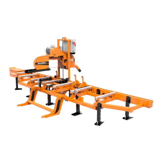
17,25MPa (2500 PSI) Max. Pressure 19MPa (2750 PSI) TABLE 1-4 See Table 1-5. 1.14 Components See Figure 1-1. The major components of the Wood-Mizer LT40 Series DH are shown below. Engine Drive Assembly HD0058 Clutch/Brake Blade Tensioner Handle Outer Blade Guide Arm... -
Page 26: Lt40 Series Dh - Hydraulic Schematic
Safety & General Information LT40 Series DH - Hydraulic Schematic 1.15 LT40 Series DH - Hydraulic Schematic RELIEF VALVE SETTING 2000 PSI LOADER CLAMP CLAMP TOEBOARD TOEBOARD TURNER IN/OUT UP/DOWN REAR FRONT RELIEF VALVE SETTING 2250 PSI HD0139C FIG. 1-2 HYDRAULIC SCHEMATIC. 1-17 HDSdoc091108 Safety &... - Page 27 Safety & General Information LT40 Series DH - Hydraulic Schematic Log Loader Clamp Clamp Turner In/Out Up/Down Side Supports Front Rear Toe Board Toe Board (Shown with handles down) HD0136B Crossflow Hose (3/8") FIG. 1-3 HYDRAULIC LAYOUT DIAGRAM. Safety & General Information HDSdoc091108 1-18...
-
Page 28: Lt40 Series Dh5 Hydraulic Schematic
Safety & General Information LT40 Series DH5 Hydraulic Schematic 1.16 LT40 Series DH5 Hydraulic Schematic FIG. 1-3 1-19 HDSdoc091108 Safety & General Information... -
Page 29: Lt40 Series Dh7 Hydraulic Schematic
Safety & General Information LT40 Series DH7 Hydraulic Schematic 1.17 LT40 Series DH7 Hydraulic Schematic FIG. 1-3 Safety & General Information HDSdoc091108 1-20... -
Page 30: Lt40 Series Dh - Hydraulic Components
Safety & General Information LT40 Series DH - Hydraulic Components 1.18 LT40 Series DH - Hydraulic Components Mfg. Part No. Wood-Mizer Description Part # CJ-S96-16-70/ 088589 Hyd. Cylinder, 70mm Bore X 178mm 32/178 Stroke CJ-S169-16-4 088590 Hyd. Cylinder, 40mm Bore X 254mm... -
Page 31: Lt40 Series Dh - Hydraulic Hoses
Safety & General Information LT40 Series DH - Hydraulic Hoses 1.19 LT40 Series DH - Hydraulic Hoses Color LENGTH Application Wood-Mizer Code "A" Part No. None 18" 1/4” Hydraulic Pump To Valve 015704 None 18" 1/4” Hydraulic Pump To Valve... - Page 32 Safety & General Information LT40 Series DH - Hydraulic Hoses Green 1.58m 3/8” Loading Arm Branch Top 014797 (62") Yellow 1.6m 3/8” Loading Arm Branch Base 014798 (63") Yellow 1.8m 3/8” Loading Arm Branch Base 093329 (71") Blue 4.34m 3/8” Loading Arm Cylinder Top (LT40S) 087795 (171") 4.9m...
- Page 33 Safety & General Information LT40 Series DH - Hydraulic Hoses ORANGE 0,40 1/4" HYDRAULIC VALVE POWER CORD TO CLAMP IN/OUT 095214 CYLINDER T-FITTING, BOTTOM (AH7) WHITE 0,40 1/4" HYDRAULIC VALVE POWER CORD TO CLAMP IN/OUT 095214 CYLINDER T-FITTING, TOP (AH7) ORANGE 7,00 1/4"...
-
Page 34: Setup & Operation Stationary Sawmill Setup
Setup & Operation Stationary Sawmill Setup SECTION 2 SETUP & OPERATION Stationary Sawmill Setup See Figure 2-1. Set up the mill on firm footing and level by eye. Fasten the mill to the floor to pre- vent any creep after prolonged use. A cement pad with 5/8” diameter anchor bolts is recom- mended. - Page 35 Setup & Operation Stationary Sawmill Setup 1. Unhook the carriage safety chain, located at the bottom of the vertical mast, near the battery box. 2. Turn the key switch on the control panel to the accessory (#3) position to enable the battery-oper- ated accessories.
-
Page 36: Portable Sawmill Setup
Setup & Operation Portable Sawmill Setup Portable Sawmill Setup WARNING! Do not set up the mill on ground with more than a 10 degree incline. If setup on an incline is necessary, put blocks under one side of the mill or dig out areas for outrigger legs to keep mill level. - Page 37 Setup & Operation Portable Sawmill Setup Adjustment Bolt Locking Pin Travel Lock Pin Outrigger Leg FIG. 2-2. OUTRIGGER ADJUSTMENT. CAUTION! If setup sawmill on a boggy terrain (such as deep mud or sand) place the board or metal plate under each outrigger leg to prevent it from sinking.
- Page 38 Setup & Operation Portable Sawmill Setup 4. Unhook the carriage safety chain, located at the bottom of the vertical mast near the battery box. 5. Turn the key switch on the control panel to the accessory (#3) position to enable the battery-oper- ated accessories.
-
Page 39: Middle Track Cover
Setup & Operation Middle Track Cover Middle Track Cover Before operating the sawmill do as follows: 1. Clean the upper and lower rails to remove any sawdust and rust preventives. 2. Unbolt and remove the middle track cover from its storage position. 3. -
Page 40: Replacing The Blade
Setup & Operation Replacing The Blade Replacing The Blade DANGER! Always disengage the blade and shut off the sawmill engine before changing the blade. Failure to do so will result in serious injury. WARNING! Always wear gloves and eye protection when han- dling bandsaw blades. -
Page 41: Tensioning The Blade
Setup & Operation Tensioning The Blade Tensioning The Blade See Figure 2-5. Tension the blade by turning the hydraulic tensioning handle clockwise until the tension gauge indicates the recommended tension. Blade Tensioner Gauge Blade Tensioner Handle Cant Control SM0243 FIG. 2-5 See Table 2-1. -
Page 42: Tracking The Blade
Setup & Operation Tracking The Blade Tracking The Blade 1. Make sure the middle blade housing cover is closed and all persons are clear of the open side of the saw head. 2. Start the engine (or motor). 3. Pull lightly on the clutch handle, rotating the blade until the blade positions itself on the wheels. WARNING! Do not spin the blade wheels by hand. -
Page 43: Starting The Engine (Or Motor)
Setup & Operation Starting The Engine (or Motor) DANGER! Make sure all guards and covers are in place and secured before operating or towing the sawmill. Failure to do so may result in serious injury. Be sure the blade housing and pulley covers are in place and secure. -
Page 44: Board Return
Setup & Operation Board Return Board Return WARNING! The automatic board return is intended to assist a second operator in removing boards quickly. Do not use the board return when operating the sawmill alone. Serious injury, death or damage to the equipment may result. WARNING! Never use the board return table as a platform to stand on. - Page 45 Setup & Operation Board Return See Figure 2-7. 3H0363 FIG. 2-7 When the blade reaches the end of the log, the arm will drop down to catch the board and drag it back toward the operator as the saw head is returned. DANGER! Keep all persons out of the path of returning boards.
-
Page 46: Hydraulic Control Operation
Setup & Operation Hydraulic Control Operation Hydraulic Control Operation The hydraulic control levers become operational when the contacts at the bottom of the carriage touch the power strip on the frame tube. The hydraulic control levers will only work when the cut- ting head is close enough to the front end of the mill to touch the power strip. - Page 47 Setup & Operation Hydraulic Control Operation See Figure 2-9. Clamping cants on sawmills equipped with DH5 hydraulic system Front Rear Clamp Clamp A/DH3 Up/Down Up/Down Front Rear HD0185 Clamp Clamp In/Out In/Out RYS. 2-9 See Figure 2-10. Clamping cants on sawmills equipped with DH7 hydraulic system 094970 Clamp Clamp...
- Page 48 Setup & Operation Hydraulic Control Operation Use the hydraulic control levers to get the mill ready to load a log. DANGER! Keep all persons out of the path of moving equipment and logs when operating sawmill or loading and turning logs. Fail- ure to do so will result in serious injury.
-
Page 49: Loading, Turning, And Clamping Logs
Setup & Operation Loading, Turning, and Clamping Logs The front toe board is raised by lifting the front toe board lever up. The rear toe board is raised by lifting the rear toe board lever up. Once a flat has been made and the log is ready to be turned, push the appropriate toe board lever down to lower either toe board until it falls below the level of the bed. - Page 50 Setup & Operation Loading, Turning, and Clamping Logs 3. Engage the clamp by raising the clamp in/out lever. Clamp the log against the side supports. 4. Lower the turner lever to lower the turner arm below the log. 5. Raise the turner arm to get a new bite on the log. 6.
- Page 51 Setup & Operation Loading, Turning, and Clamping Logs To Clamp Logs 1. Raise the clamp in/out lever and clamp the log against the side supports. 2. Lower the turner lever until the turner arm falls below the bed. 3. When the turner arm is lowered all the way, the side supports will begin to lower. Back the clamp off slightly, and let the side supports come down until they are positioned below the level of your first few cuts.
-
Page 52: Up/Down Operation
Setup & Operation Up/Down Operation 2.11 Up/Down Operation 1. Install a blade, if needed, and check for correct blade tension. (See Section 2.5). 2. Set the cutting head to the desired height. (The blade height scale shows the height of the blade above the bed rails.) See Figure 2-11. -
Page 53: Blade Guide Arm Operation
Setup & Operation Blade Guide Arm Operation 2.12 Blade Guide Arm Operation 1. Look down the length of the log to see its maximum width. The outer blade guide should be adjusted to clear the widest section of the log by less than 1" (25.4 mm). 2. -
Page 54: Clutch/Brake Operation
Setup & Operation Clutch/Brake Operation 2.13 Clutch/Brake Operation NOTE: If your sawmill is equipped with the Remote Option, see the option manual for clutch/brake operation. 1. Clear any loose objects from the area of the blade, motor, and drive belt. 2. -
Page 55: Power Feed Operation
Setup & Operation Power Feed Operation 4. To engage the blade, pull the lever down until it locks in the down position. This engages the drive mechanism, releases the blade brake, and increases the engine speed to full throttle. To disengage the blade, raise the clutch/brake lever to the up position. This disengages the drive belt, engages the blade brake, and returns the engine to idle. - Page 56 Setup & Operation Power Feed Operation The middle position (as shown) is the neutral position. The power feed switch is designed to return to the neutral or "off" position when released from operating in the reverse position. If the switch remains engaged, manually move the switch to the neutral or "off"...
-
Page 57: Cutting The Log
Cutting The Log 2.15 Cutting The Log The following steps guide you through normal operation of the Wood-Mizer sawmill. 1. Once the log is placed where you want it and clamped firmly, turn the key switch to the accessory (#3) position. -
Page 58: Edging
1 1/16 - 1 1/8" (27-28.6 mm) for each board. 2.16 Edging The following steps guide you through edging boards on the Wood-Mizer sawmill. 1. Raise the side supports to 1/2 the height of the flitches, or the boards that need to be edged. -
Page 59: Optional Cutting Procedure For Super Series Mills
Setup & Operation Optional Cutting Procedure for Super Series Mills 2.17 Optional Cutting Procedure for Super Series Mills In order to achieve maximum production rates with Super Series mills; it may be desirable to leave the blade engaged when returning the carriage. (Normal operation procedures recommend disen- gaging the blade before returning the carriage for maximum blade life and fuel economy.) DANGER! If leaving the blade engaged for maximum production... - Page 60 Setup & Operation Blade Height Scale indicator, used to read the inch and quarter scales, remains stationary. Blade Height Indicator The blade height indicator has two horizontal, red lines on both sides. Readings should be taken with eyes level with the indicator, when the two red lines are in line. This will allow to avoid the parallax error (different scale readings depending on the angle of vision).
-
Page 61: Water Lube Operation
Setup & Operation Water Lube Operation indicator with the nearest mark on the scale you want to use. Make a trim cut. When you return the carriage for a second cut, lower the carriage to the next mark on the scale. This mark shows where the blade should be positioned to cut a certain thickness of lumber, without having to measure on the inch scale. -
Page 62: Preparing The Sawmill For Towing
Return the forward/reverse switch to neutral and turn the key switch to off (#0). 2.20 Preparing The Sawmill For Towing The Wood-Mizer trailer package makes transporting your sawmill easy and convenient. To get your sawmill ready for towing, follow these instructions. CAUTION! - Page 63 Setup & Operation Preparing The Sawmill For Towing See Figure 2-17. Rest Pin Lock Pin HD0075 FIG. 2-17 8. Continue lowering the head 3/4" (19mm) until it contacts the stop blocks on the mast rails. CAUTION! It is important that the lower stop bolts are properly adjusted to secure the carriage on the track rail.
- Page 64 Setup & Operation Preparing The Sawmill For Towing traveling. Be sure to disengage the clutch/brake handle after reaching the destination to avoid deformation of the drive belt. 11. Hook the carriage safety chain located at the bottom of the carriage to the bracket at the bottom of the mast.
-
Page 65: Maintenance
Maintenance Wear Life SECTION 3 MAINTENANCE This section lists the maintenance procedures that need to be performed. The Short Interval Maintenance Schedule lists procedures that need to be performed every 4, 8 or 25 hours.The Maintenance Log lists procedures that need to be performed every 50, 100, 200, or 1000 hours. -
Page 66: Blade Guides
Maintenance Blade Guides Blade Guides 1. Check the rollers for performance and wear every blade change. Make sure the rollers are clean and spinning freely. If not, rebuild them. Replace any rollers which have worn smooth or have become cone shaped. See The LT40 Series DH Parts manual for blade guide rebuild kits and complete roller assemblies. - Page 67 Maintenance Blade Guides IMPORTANT! The inserts should be parallel to the blade. Check the space between the insert and the blade at each side of the insert to insure it is parallel. Use the appropriate outer adjust- ment bolt to tilt the insert mounting plate so the insert is parallel to the blade.
-
Page 68: Sawdust Removal
Maintenance Sawdust Removal Sawdust Removal 1. Remove the excess sawdust from the blade wheel housings and sawdust chute every blade change. 2. Remove all sawdust and debris from around the velocity fuse valves every 8 hours of operation. The valves are located at the bottom of the log loader cylinders. 3. - Page 69 Maintenance Carriage Track, Wiper & Scrapers FIG. 3-3 Maintenance HDSdoc091108...
-
Page 70: Vertical Mast Rails
Lubricate the up/down and power feed drum switch contacts inside the control panel every fifty hours of operation. Use only contact grease supplied by Wood-Mizer. Remove the control panel cover. Use a cotton swab to apply grease to the switch contact ends. -
Page 71: Miscellaneous
Maintenance Miscellaneous Miscellaneous 1. Apply a thin film of a NLGI No. 2 grade lithium grease to the blade guide arm every fifty hours of operation to help prevent it from rusting. 2. Grease the clamp mechanism, loading arm, and side supports with a NLGI No. 2 grade lithium grease every fifty hours of operation. -
Page 72: Blade Tensioner
Maintenance Blade Tensioner Blade Tensioner 1. Lubricate the chrome rods of the tensioner system with a heavy duty teflon spray lubricant, such as Gunk L508, every fifty hours of operation. 2. Lubricate the tensioner screw handle with a NLGI No. 2 grade lithium grease as needed. See Figure 3-4. -
Page 73: Blade Wheel Belts
Maintenance Blade Wheel Belts Manually extend the rear piston (the front piston should remain extended). Use a small funnel or cup to completely fill the block with hydraulic fluid. When full, place the fill plug in the fill plug hole and thread 1-2 turns. Manually push the rear piston all the way in to allow excess oil and air to bleed from system through the plug. - Page 74 Maintenance Brake Strap Adjustment See Figure 3-6. Loosen the two nuts on the upper brake strap bracket. Slide the bracket and brake strap down until snug. Retighten the bolts. Replace the belt cover. FIG. 3-6 3-10 HDSdoc091108 Maintenance...
-
Page 75: Drive Belt Adjustment
Maintenance Drive Belt Adjustment 3.11 Drive Belt Adjustment WARNING! Do not for any reason adjust the engine drive belts or belt support bracket with the engine running. Doing so may result in serious injury. See Table 3-2. Check the drive belt tension after the first 20 hours, and every 50 hours thereafter. See the table below for drive belt tension specifications for your model sawmill. - Page 76 Maintenance Drive Belt Adjustment See Figure 3-8. Hold top portion with wrench Turn bottom jam nut clockwise to tighten belt 3H0505-3 FIG. 3-8 4. Gas/Diesel Engines Only: After tensioning the drive belt, check throttle cable tension and adjust if necessary. The throttle cable should be tensioned just enough so that the engine revs as soon as the clutch/brake handle is engaged.
- Page 77 Maintenance Drive Belt Adjustment Adjust the drive belt support as needed. The drive belt support is designed to extend belt life. The bracket should be adjusted to NOT touch the drive belt when the clutch handle is engaged (down position), AND to hold the drive belt away from the engine pulley when the clutch handle is disen- gaged (up position).
-
Page 78: Clutch Handle Adjustment
Maintenance Clutch Handle Adjustment 3.12 Clutch Handle Adjustment After the drive belts and brake strap are properly adjusted, the clutch handle should lock in the down position when the drive belts are engaged. If the clutch handle does not stay locked, adjust the handle turnbuckle. -
Page 79: Autoclutch Option Adjustment
Maintenance Autoclutch Option Adjustment 3.13 Autoclutch Option Adjustment If your sawmill is equipped with the Autoclutch option, check the clutch linkage after every drive belt or brake strap adjustment. 1. Remove the blade from the sawmill. 2. Remove the inside belt guard and push the Autoclutch switch up to engage the drive belts. 3. -
Page 80: Hydraulic System
Maintenance Hydraulic System 3.14 Hydraulic System 1. Check the hydraulic fluid level every fifty hours of operation. Add fluid as necessary. The level in the hydraulic pump should be 3/4" (19mm) from the top with all cylinders collapsed. If humidity is a problem or the mill is used outside in humid weather, drain and replace two quarts (.95 liters) of fluid every six months. -
Page 81: Drive Bearing
Maintenance Drive Bearing 3.15 Drive Bearing Refill the fluid in the drive-side cylinder bearing housing every 500 hours of operation. Remove the top and bottom oil plugs. Pour an Automatic Transmission Fluid (ATF) such as UNIVIS J26 or Dexron III ATF into the top hole until it begins to flow from the bottom hole. Reinstall the square oil plug to the bottom hole and the vented oil plug to the top hole. -
Page 82: Up/Down System
Maintenance Up/Down System 3.16 Up/Down System 1. Grease the up/down gear reducer shaft bearing with a NLGI No. 2 grade lithium grease every 1000 hours of operation. 1000 See Figure 3-14. Up/Down Gear Reducer Shaft Bearing 3H0016B FIG. 3-14 2. Super model up/down systems feature a spring loaded belt design. Belt tension is automatically maintained and requires no adjustment. - Page 83 See Figure 3-15. FIG. 3-15 4. Check the up/down gearbox oil level. Add a synthetic gear oil such as Mobil SHC 634 as needed. Wood-Mizer offers replacement gear oil in 8 ounce bottles (2 required for complete oil replace- ment). Maintenance...
-
Page 84: Power Feed
Maintenance Power Feed 3.17 Power Feed 1. Adjust the power feed belt as needed. When the power feed belt gets loose, it will begin slipping. This causes the carriage to not move forward when cutting. To retighten the belt: See Figure 3-16. Remove the four cover bolts and belt cover and measure the belt tension. The belt should be tightened so there is 1/8"... - Page 85 Maintenance Power Feed See Figure 3-17. 3H0018B Feed Chain Adjustment Nuts FIG. 3-17 Maintenance HDSdoc091108 3-21...
- Page 86 LT40 Series A/DH Short Interval Maintenance Schedule (Check engine and option manuals for additional maintenance procedures) PROCEDURE MANUAL REFERENCE EVERY BLADE CHANGE Check Blade Guide Roller Performance See Section 3.2 Remove Excess Sawdust From Blade Wheel Housings And Sawdust Chute See Section 3.3 Check Blade Screw See Section 3.2...
- Page 87 WOOD-MIZER LT40 SERIES A/DH MAINTENANCE LOG (Check Engine And Option Manuals For Additional Maintenance Procedures) PROCEDURE MANUAL TOTAL HOURS OF OPERATION REFERENCE FILL IN THE DATE AND THE MACHINE HOURS AS YOU PERFORM EACH PROCEDURE. A SHADED BOX INDICATES MAINTENANCE IS NOT NEEDED AT THIS TIME.
- Page 88 WOOD-MIZER LT40 SERIES A/DH MAINTENANCE LOG (Check Engine And Option Manuals For Additional Maintenance Procedures) PROCEDURE MANUAL TOTAL HOURS OF OPERATION REFERENCE FILL IN THE DATE AND THE MACHINE HOURS AS YOU PERFORM EACH PROCEDURE. A SHADED BOX INDICATES MAINTENANCE IS NOT NEEDED AT THIS TIME.
- Page 89 WOOD-MIZER LT40 SERIES A/DH MAINTENANCE LOG (Check Engine And Option Manuals For Additional Maintenance Procedures) PROCEDURE MANUAL TOTAL HOURS OF OPERATION REFERENCE FILL IN THE DATE AND THE MACHINE HOURS AS YOU PERFORM EACH PROCEDURE. A SHADED BOX INDICATES MAINTENANCE IS NOT NEEDED AT THIS TIME.
- Page 90 WOOD-MIZER LT40 SERIES A/DH MAINTENANCE LOG (Check Engine And Option Manuals For Additional Maintenance Procedures) PROCEDURE MANUAL TOTAL HOURS OF OPERATION REFERENCE FILL IN THE DATE AND THE MACHINE HOURS AS YOU PERFORM EACH PROCEDURE. A SHADED BOX INDICATES MAINTENANCE IS NOT NEEDED AT THIS TIME.
- Page 91 WOOD-MIZER LT40 SERIES A/DH MAINTENANCE LOG (Check Engine And Option Manuals For Additional Maintenance Procedures) PROCEDURE MANUAL TOTAL HOURS OF OPERATION REFERENCE FILL IN THE DATE AND THE MACHINE HOURS AS YOU PERFORM EACH PROCEDURE. A SHADED BOX INDICATES MAINTENANCE IS NOT NEEDED AT THIS TIME.
-
Page 92: Troubleshooting Guide Sawing Problems
Troubleshooting Guide Sawing Problems SECTION 4 TROUBLESHOOTING GUIDE Sawing Problems PROBLEM CAUSE SOLUTION Blades Dull Quickly Dirty logs Clean or debark logs, espe- cially on entry side of the cut When grinding teeth, heating Grind just enough metal to too much and causing teeth to restore sharpness to the soften teeth. - Page 93 Troubleshooting Guide Sawing Problems PROBLEM CAUSE SOLUTION Boards Thick Or Thin On Stress in log which causes log After log has been squared, Ends Or Middle Of Board. to not lay flat on the bed. take equal cuts off opposing sides.
-
Page 94: Electrical Problems
Replace drum switch or remove control panel cover and clean and lubricate con- tacts NOTE: Use only contact grease supplied by Wood-Mizer. Drum switch spring broken. Manually move the power feed or up/down switch back to neutral or "off" position. - Page 95 Troubleshooting Guide Electrical Problems Up/Down Or Power Feed System overload or bind Correct problem. See Section Motors Overheat And Loose occurred. 4.3 Power Feed Problems. Power. Allow motor to cool before restarting. Normal operation factors Allow motor to cool before exceeded (eg: up/down con- restarting.
-
Page 96: Power Feed Problems
Drum switch is dirty. Clean drum switch and lubricate Speeds Or Does Not Move with contact grease supplied by Until Speed Is Above Halfway Wood-Mizer. Mark. Drum switch contacts are bad Check that contacts are in good condition and positively close cir- cuit. - Page 97 Troubleshooting Guide Power Feed Problems PROBLEM CAUSE SOLUTION Power Feed Motor Overheats. Middle track oiler is dragging. Clean middle track oiler and lubricate with 30-weight oil or ATF (Automatic Transmission Fluid) such as Dexron II. Allow motor to cool before restarting. Ground is not level.
-
Page 98: Power Feed Circuit Troubleshooting
Troubleshooting Guide Power Feed Circuit Troubleshooting Power Feed Circuit Troubleshooting LED lights are provided on the control module to help troubleshoot any feed problems you may encounter. See Figure 4-1. The lights can be viewed by removing the rear control box panel. DETAIL Detail 3H0400B-3... -
Page 99: Hydraulic Problems
See Monarch manual for trou- noid, check solenoid. Tapping bleshooting solenoid on solenoid may fix tempo- rarily. Replace solenoid if nec- essary. NOTE: The solenoid is not a standard automotive type. Order from Wood-Mizer only Troubleshooting Guide HDSdoc091108... - Page 100 Troubleshooting Guide Hydraulic Problems You Can Get Response From Valve assembly switch con- Locate the valve switch at the the Pump By Actuating All tacts are not properly adjusted bottom of the valve assembly. But One or Two Handles Use a 3MM allen wrench to loosen the set screw on each of the five switch contacts.
- Page 101 Troubleshooting Guide Hydraulic Problems PROBLEM CAUSE SOLUTION Pump Motor Runs With Little Low battery Test battery. Recharge or Or No Response From The replace as necessary Cylinders Low fluid level Check fluid level. Add an all-season hydraulic fluid such as Amoco Rycon Oil MV or Mobil Multipurpose ATF (auto- matic transmission fluid) until level is 4 - 4 1/2"...
- Page 102 Troubleshooting Guide Hydraulic Problems PROBLEM CAUSE SOLUTION Hydraulic Side Supports Go Dirt in sequence valve Remove sequence valves and Down Before Or At Same clean thoroughly with kero- Time As Log Turner sene. NOTE: Be sure to reas- semble the valve and install it in its original position on the cylinder Retainer in sequence valve...
-
Page 103: Engine/Motor And Drive Pulleys Alignment
Troubleshooting Guide Engine/Motor and Drive Pulleys Alignment Engine/Motor and Drive Pulleys Alignment 1. Install the drive belt. 2. Use a straight edge to align the engine/motor pulley to the drive pulley. Also check that the engine pulley is within 1/8" square with the drive pulley. Loosen the engine mounting bolts and rotate the engine if necessary. -
Page 104: Fuse Terminal Extension Stud
Troubleshooting Guide Fuse Terminal Extension Stud 9. Make sure the power feed belt is properly tightened. Operate the loading arm hydraulic lever and read the pressure on the gauge. Hydraulic pressure is factory-set at 2000 ±100 psi and should not need to be readjusted. The relief valve adjustment screw shown may be used to fine-tune the hydraulic pressure. -
Page 105: Circuit Breaker Operation
Troubleshooting Guide Circuit Breaker Operation 3. Attach the positive cable from a battery charger or jumper cables to the extension stud. 4. Connect the negative cable from the charger or jumper cables to a grounded metal surface. The mounting bolts on the bottom of the control box are an acceptable ground. 5. - Page 106 Troubleshooting Guide Circuit Breaker Operation Internal Circuit Breakers (Remove Panel) Accessory Start Board Blade Ignition Return Guide External External Power Feed Up/Down Circuit Breaker Circuit Breaker 3H0550-2 FIG. 4-3 4-15 HDSdoc091108 Troubleshooting Guide...
-
Page 107: Sawmill Alignment
SECTION 5 SAWMILL ALIGNMENT Pre-Alignment Procedures The Wood-Mizer sawmill is factory aligned. Two alignment procedures are available to realign the sawmill if necessary. The Routine Alignment instructions should be performed as necessary to solve sawing problems not related to blade performance. The Complete Alignment procedure should be performed approximately every 1500 hours of operation (sooner if you regularly trans- port the sawmill over rough terrain). -
Page 108: Frame Setup
Sawmill Alignment Frame Setup Frame Setup Stationary sawmills should be setup on firm, level ground before proceeding with alignment. Shim the feet so the weight of the sawmill is evenly supported. Portable sawmills should also be setup on firm, level ground: LT40S: Adjust the two middle outriggers on the main frame tube down just enough to lift weight from the trailer tire. - Page 109 Sawmill Alignment Blade Installation And Alignment saw head. 2. Start the engine (or motor). 3. Pull lightly on the clutch handle, rotating the blade until the blade positions itself on the wheels. WARNING! Do not spin the blade wheels by hand. Spinning the blade wheels by hand may result in serious injury.
- Page 110 Sawmill Alignment Blade Installation And Alignment Adjustment with the cant control is usually all that is required to track the blade properly on both blade wheels. The drive-side blade wheel will usually not have to be adjusted. If necessary, the drive-side wheel can be adjusted as follows: See Figure 5-3.
-
Page 111: Saw Head Slide Pad Adjustment
Sawmill Alignment Saw Head Slide Pad Adjustment Saw Head Slide Pad Adjustment There are eight nylon pads positioned between the saw head frame and vertical mast. The spac- ing of the pads is factory set and rarely needs adjusting. To check the pad spacing, perform the fol- lowing steps. - Page 112 Sawmill Alignment Saw Head Slide Pad Adjustment 1. Raise the saw head to the top of the vertical mast and secure the saw head with a chain at the top, or shim it underneath. Check the top set of four pads.The outer two pads should be touching the mast rails.
-
Page 113: Adjusting The Lower Track Rollers
Sawmill Alignment Adjusting The Lower Track Rollers Adjusting The Lower Track Rollers See Figure 5-5. Making these adjustments correctly will give you square cuts and accurate dimen- sions across the width of your boards. 1. Using the feed controls, move the saw carriage so that the blade is positioned over the front pivot end rail. - Page 114 Sawmill Alignment Adjusting The Lower Track Rollers 5. Remove the blade guides, or adjust them so that they do not touch the blade. 6. Open the adjustable blade guide arm to within 1/2" (15 mm) of full open. 7. Move the carriage back to the front pivot end rail. Raise the cutting head until the bottom of the blade is 17"...
-
Page 115: Adjusting Bed Rails To The Blade
Sawmill Alignment Adjusting Bed Rails To The Blade Adjusting Bed Rails To The Blade 1. Move the vertical clamp to its lowest position. Before using the clamp tube as a reference to set the blade, make sure it is level. 2. - Page 116 Sawmill Alignment Adjusting Bed Rails To The Blade 5. Move the saw head back to power the hydraulics and move the clamp so it is 10" from the clamp stop. Move the saw head forward until it is positioned over the clamp. Raise the saw head until the blade measures 15 5/16"...
- Page 117 Sawmill Alignment Adjusting Bed Rails To The Blade See Figure 5-9. FIG. 5-9 14. Loosen the bed rail clamping bolts and turn the adjustment bolts to move the bed rails to the blade if necessary. 15. Retighten the clamping bolts and adjustment bolts. 16.
-
Page 118: Blade Guide Arm Vertical Adjustment
Sawmill Alignment Blade Guide Arm Vertical Adjustment Blade Guide Arm Vertical Adjustment 1. Move the saw head so that the blade guide arm is directly over a bed rail. 2. Adjust the blade guide arm out to within 1/2" (15 mm) of full open. 3. -
Page 119: Blade Guide Arm Horizontal Adjustment
Sawmill Alignment Blade Guide Arm Horizontal Adjustment 6. The rollers are mounted on cam bolts that raise or lower the arm when turned. To adjust the rollers, locate the cam bolt head inside the housing and turn until the arm is lowered or raised as needed. - Page 120 Sawmill Alignment Blade Guide Arm Horizontal Adjustment 3. If adjustment is needed, the guide rollers can be adjusted in or out on the threaded mounts to open or close the gap. See Figure 5-12. Adjustment Nuts Adjustment Nuts SM0066 FIG. 5-12 4.
-
Page 121: Aligning The Blade Guides
Aligning the Blade Guides Aligning the Blade Guides Each Wood-Mizer sawmill has two blade guide assemblies that help the blade maintain a straight cut. The two blade guide assemblies are positioned on the saw head to guide the blade on each side of the material being cut. -
Page 122: Blade Deflection
Sawmill Alignment Blade Deflection 5.10 Blade Deflection Perform the following steps to achieve proper blade deflection with the blade guides. 1. Raise the carriage until the blade is 15" (375 mm) above a bed rail. Measure the actual distance with a tape from the top of the rail to the bottom of the blade. 2. -
Page 123: Blade Guide Vertical Tilt Adjustment
Sawmill Alignment Blade Guide Vertical Tilt Adjustment 5.11 Blade Guide Vertical Tilt Adjustment Check that the blade guide does not tilt the blade up or down. A Blade Guide Alignment Tool (BGAT) is provided to help you measure the vertical tilt of the blade. 1. - Page 124 Sawmill Alignment Blade Guide Vertical Tilt Adjustment See Figure 5-15. Loosen jam nuts and turn screws to tilt roller up or down Sm0070c FIG. 5-15 8. Move the carriage forward so the back end of the tool is over the bed rail. 9.
-
Page 125: Blade Guide Spacing
Sawmill Alignment Blade Guide Spacing 5.12 Blade Guide Spacing HINT: When adjusting blade guide spacing, loosen the top set screw and one side set screw only. This will ensure horizontal and vertical tilt adjustments are maintained when the set screws are retightened. -
Page 126: Horizontal Tilt Adjustment
Sawmill Alignment Horizontal Tilt Adjustment 5.13 Horizontal Tilt Adjustment 1. Finally, both blade guides must be tilted horizontally. Adjust the blade guide arm halfway in. See Figure 5-17. FIG. 5-17 2. Place the Blade Guide Alignment Tool against the face of the outer blade guide roller. 3. -
Page 127: Blade Guide Block Adjustment
Sawmill Alignment Blade Guide Block Adjustment 5.14 Blade Guide Block Adjustment To ensure correct cutting, adjust the gap between the blade guide block and the blade. Perform the adjustment with the blade installed and properly tensioned. See Figure 5-18. Loosen both nuts and retaining bolts. Use the adjustment bolt to raise or lower the disc until its distance from the blade is .2 - .25 mm. -
Page 128: Horizontal Adjustment Of Side Supports
Sawmill Alignment Horizontal Adjustment of Side Supports 5.15 Horizontal Adjustment of Side Supports Logs and boards are clamped against the side supports when sawing. The sides supports must be square to the bed to ensure square lumber. 1. Swing the side support down. 2. -
Page 129: Vertical Adjustment Of Side Supports
Sawmill Alignment Vertical Adjustment of Side Supports 5.16 Vertical Adjustment of Side Supports 1. Place a flat board across the bed rails. 2. Swing a side support up so that it is vertical. 3. Pull back at the top of the support to eliminate slack as if a log were being clamped against it. See Figure 5-21. -
Page 130: Clamp Stop/Stop Bolt Adjustment
Sawmill Alignment Clamp Stop/Stop Bolt Adjustment 5.17 Clamp Stop/Stop Bolt Adjustment 1. Once the side supports are aligned, pivot them down to their horizontal position. 2. Tie a string across the face of the side supports. See Figure 5-22. 3. Loosen the clamp stop bolts and adjust the clamp stop until it touches the string. Loosen the jam nut and adjust the bolt on the middle-rear bed rail until it touches the string. -
Page 131: Saw Head Tilt
Sawmill Alignment Saw Head Tilt 5.18 Saw Head Tilt As the blade enters a wide log or cant, the outside of the saw head will drop down slightly. To com- pensate for the drop, use the lower track roller horizontal bolts to raise the outside of the saw head 1/16"... -
Page 132: Blade Height Scale Adjustment
Sawmill Alignment Blade Height Scale Adjustment 5.19 Blade Height Scale Adjustment After the entire sawmill has been aligned and all adjustments made, check that the blade height scale indicates the true distance from the blade to the bed rails. 1. Move the saw head so the blade is positioned directly above one of the bed rails. Measure from the bottom edge on a down-set tooth of the blade to the top of the bed rail (or stainless steel sleeve if applicable). -
Page 133: Board Return Bracket
Sawmill Alignment Board Return Bracket 5.20 Board Return Bracket Adjust the board return bracket so the bottom edge is positioned 1/4" below the bottom of the blade. 1. With a square cant on the bed rails, lower the blade until it touches the top of the cant. Then raise the saw head 1/4"...
Need help?
Do you have a question about the LT40 DH Series and is the answer not in the manual?
Questions and answers