Table of Contents
Advertisement
Advertisement
Table of Contents

Subscribe to Our Youtube Channel
Related Manuals for Wood-mizer BMT300


Summary of Contents for Wood-mizer BMT300
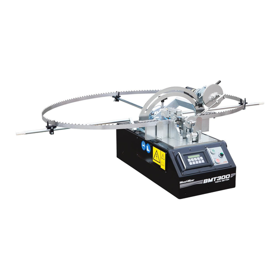
- Page 1 Wood-Mizer ® Safety, Operation, Maintenance & Parts Manual Automatic Setter BMT300 Rev. B.03 Safety is our #1 concern! Read and understand all safety information and instructions before operating, setting up or maintaining this machine. June 2009 Form #1033...
-
Page 2: Table Of Contents
Table of Contents Section-Page SECTION 1 GENERAL INFORMATION AND SAFETY Electrical Safety......................1-1 Blade Handling......................1-2 Machine Operation ....................1-2 Noise Level........................ 1-3 Motor Specifications ....................1-3 Technical Data......................1-3 Setter Components..................... 1-5 Control Panel Components..................1-6 Start Up Modes......................1-8 1.10 Blade Settings...................... - Page 3 Blade Support Arms, Index Plate ................6-15 6.10 Stand Option......................6-16 6.11 Decals, BMT300...................... 6-17 6.12 3" Blade Support Kit - Aut. Toothsetter (Option) ..........6-18 SECTION 7 ELECTRICAL INFORMATION BMT300 Electrical Diagram ..................7-1 Electrical Components....................7-4 Electrical Component Layout..................7-4 Table of Contents doc052814...
- Page 4 Table of Contents Section-Page SECTION 1 GENERAL INFORMATION AND SAFETY Electrical Safety......................1-1 Blade Handling......................1-2 Machine Operation ....................1-2 Noise Level........................ 1-3 Motor Specifications ....................1-3 Technical Data......................1-3 Setter Components..................... 1-5 Control Panel Components..................1-6 Start Up Modes......................1-8 1.10 Blade Settings......................
- Page 5 Blade Support Arms, Index Plate ................6-15 6.10 Stand Option......................6-16 6.11 Decals, BMT300...................... 6-17 6.12 3" Blade Support Kit - Aut. Toothsetter (Option) ..........6-18 SECTION 7 ELECTRICAL INFORMATION BMT300 Electrical Diagram ..................7-1 Electrical Components....................7-4 Electrical Component Layout..................7-4 Table of Contents doc052814...
-
Page 6: General Information And Safety
General Information and Safety Electrical Safety SECTION 1 GENERAL INFORMATION AND SAFETY This symbol calls your attention to instructions concerning your personal safety. Be sure to observe and follow these instructions. This symbol accompanies a signal word. The word DANGER indicates an imminently hazardous situation which, if not avoided, will result in death or serious injury. -
Page 7: Blade Handling
General Information and Safety Blade Handling restore power until all access panels are replaced and secured. WARNING! Always turn off and disconnect power at control console AND at main supply circuit breaker before performing any service to the machine. Blade Handling WARNING! Always wear gloves and eye protection when handling bandsaw blades. -
Page 8: Noise Level
General Information and Safety Noise Level Noise Level See Table 1-1. The level of noise generated by the BMT300 Toothsetter is given in the table below Max. Noise Level BMT300BMT300 74.8 dB (A) TABLE 1-1 Motor Specifications See Table 1-2. The motor specifications are listed below. - Page 9 General Information and Safety Technical Data See the table below for air supply specifications: Air Supply Pressure BMT300 Min. 4 bar TABLE 1-4 General Information and Safety SISdoc052814...
-
Page 10: Setter Components
Setter Components Setter Components The BMT 300 toothsetter is designed to work with the Wood-Mizer blades only (types of the blades are shown in Table 1-5 on page 10). See Figure 1-1. The major component and dimensions of the Automatic Setter are listed below. -
Page 11: Control Panel Components
General Information & Safety Control Panel Components Control Panel Components See Figure 1-2. The control panel component locations and their functions are listed below. Display ON/OFF Switch CLEAR/ MENU ENTER ABORT Manual Manual Single Zero Clamp Index Bend Cycle Calibrate DOWN arrow SI0003 UP arrow... - Page 12 General Information & Safety Control Panel Components F1 Clamp - press to close or open the blade clamp. F2 Manual Index - press to move the blade to the next tooth. F3 Manual Bend - used to bend the blade teeth manually regardless of set; the tooth set is not checked.
-
Page 13: Start Up Modes
General Information & Safety Start Up Modes Start Up Modes Press the MENU button once to get to the menu selection mode. Press the UP or DOWN button twice to find the MODE menu. The following options are available in the MODE menu: Set Single Clamp - The setter clamps and checks the blade tooth. -
Page 14: Blade Settings
General Information & Safety Blade Settings 1.10 Blade Settings Press the MENU button on the control panel once to enter the BLADE SETTINGS mode. Use the UP or DOWN arrows if necessary. Push the ENTER button to enter the settings. The following options are available in the BLADE SETTINGS menu: No. - Page 15 General Information & Safety Blade Settings See Table 1-5. Recommended blade settings are shown below. Blade Number of teeth Lower Set Limit Upper Set Limit Raker Set Blade Type Thickness (Value Entered) (Value Entered) (Value Entered) (standard blades) 175 158 10 S .035"...
-
Page 16: System Parameters
General Information & Safety System Parameters 1.11 System Parameters Press the MENU button once. Push the DOWN arrow button to find the SYSTEMS PARAMETERS menu. Press ENTER to see parameters needed to be set. When selected, the following parameters can be set: Max Tooth Set Errors - push the ENTER button to enter the "Max Set Errors #"... -
Page 17: Diagnostic & Setup
General Information & Safety Diagnostic & Setup 1.12 Diagnostic & Setup To enter the DIAGNOSTIC/SETUP menu, press the MENU button. Press the UP arrow once, and push ENTER to confirm. Use the UP and DOWN arrows to switch options. The following options are available in the DIAGNOSTIC/SETUP menu: Raw A/D value - technical specifications. -
Page 18: Operation
Operation Machine Setup SECTION 2 OPERATION Machine Setup 1. Install the blade to the setter. Rest the blade on the inside of the two blade guides and in between both blade clamps. Center the blade on the setter stand. Position the three adjustable blade guide supports so they lightly touch the inside of the blade. -
Page 19: 3" Blade Support Setup (Option)
Operation 3" Blade Support Setup (Option) 3. Adjust the pusher pin. To adjust, manually rotate the pusher adjustment knob. Turn the pusher adjustment knob clockwise to increase the pusher pin force, turn the knob coun- terclockwise to decrease the force. Make sure the tooth is not being bent too much. Read the display to check the tooth set while adjusting. - Page 20 Operation 3" Blade Support Setup (Option) AS80_015 FIG. 2-2 SISdoc052814 Operation...
-
Page 21: Preliminary Setup
Operation Preliminary Setup Preliminary Setup 1. Clean the machine as needed with a solution of 1 part liquid Dawn detergent to 9 parts water. Use an air hose to blow any dust or debris from the blade clamp and up/down com- ponents. - Page 22 Operation Preliminary Setup See Figure 2-1. FIG. 2-1 5. Turn the ON/OFF switch to the ON position. 6. Calibrate the setter if necessary. See Section 3.1 Setter Calibration. 7. Make all the adjustments necessary to start the setting operation. See Sections 1.6 through 1.8.
-
Page 23: Machine Operation
Operation Machine Operation Machine Operation 1. Clean the blade and deburr before putting in the toothsetter. Otherwise, sap buildup on the blade or tooth will give false set readings. Metal burrs created by sharpening will also cause false readings. 2. Mount the blade in the toothsetter. Place blade between the clamping plates and on the three guide assemblies. - Page 24 Operation Machine Operation 6. The machine will automatically stop after the setting operation has been completed. 7. Remove the blade and invert it. 8. Swing the index motor assembly to the other side. Repeat the setting operation. SISdoc052814 Operation...
-
Page 25: Maintenance
Maintenance Setter Calibration SECTION 3 MAINTENANCE Setter Calibration To calibrate: 1. Clean each clamp block with air. If oily, wipe dry with a clean rag. WARNING! Never spray a liquid on or near the sensor assembly. 2. Inspect the blocks for chips and/or other damage. Replace if necessary. 3. -
Page 26: Alignment
Alignment Sensor Adjustment SECTION 4 ALIGNMENT Check and align the setter each time the linear sensor is replaced. Sensor Adjustment 1. Turn the ON/OFF switch to the ON position. 2. Check the air pressure. Make sure the air pressure gauge indicates 60 P.S.I. Adjust the pressure if necessary. - Page 27 Alignment Sensor Adjustment 5. Remove the two screws securing the sensor guard and remove the sensor guard. See Figure 4-2. Remove the two screws and the sensor guard Loosen the bolts to adjust the sensor SI0005B Move the linear sensor; check the display while adjusting FIG.
-
Page 28: Troubleshooting
Troubleshooting Error Messages SECTION 5 TROUBLESHOOTING Error Messages See Table 5-1. The possible error messages and their causes are listed below: MESSAGE CAUSE SOLUTION Error --- A/D Power supply failure. Check connecting cable. A/D Failure A/D module has broken. Check the A/D module connections. Replace if necessary. -
Page 29: Replacement Parts
PLATE, MOTOR MOUNT 101382-1 SCREW, M6X20-10.9 FE/ZN5 DIN-7991 F81001-17 BOLT, #10-32 X 5/8” HEX HEAD F05004-152 WASHER, 5.1 SPLIT LOCK ZINC F81052-2 SHAFT, BMT300 DRIVE 101381-1 SCREW, M4X6 ISO4028 SET F81014-6 HOUSING, BMT300 BEARING 101383-1 HANDLE, INDEX PIVOT 500040-1 GRIP, HANDLE 1/2IDX3 LG... - Page 30 SCREW, M6x10-45H Fe/Zn5 PN84/M-82314 SET F81001-26 Plate, BMT300 Cam 101393-1 BOLT, M10 X 25 8.8, PN-M/82302 F81003-32 SCREW,M6X10 8.8 HEX SOCKET HEAD CAP ZINC F81001-12 SHAFT, BMT300 INDEX PIVOT 500041 PAWL ASSY, BMT300 PUSH 500047 BLOCK, BMT300 PUSH PAWL 500046-1 NUT, M10-8-B-FE F81033-3...
-
Page 31: Cam Drive Unit Assembly
Cam Drive Unit Assembly Cam Drive Unit Assembly AS80_002 REF. DESCRIPTION ( Indicates Parts Available In Assemblies Only) PART # QTY. CAM DRIVE ASSEMBLY, BMT300 101387 MOTOR ASSEMBLY, 24V 60 RPM GEAR 035659 PLATE, BMT300 MOTOR MOUNT 101382-1 SCREW, M6X20-10.9 FE/ZN5 DIN-7991 F81001-17 BOLT, #10-32 X 5/8”... - Page 32 Cam Drive Unit Assembly RING, W40 SPRING RETAINING F81090-3 PLATE, CAM 101385-1 SCREW, M6x10-45H Fe/Zn5 PN84/M-82314 SET F81001-26 CAM, BMT300 SET 101386-1 SCREW, M10x25 8.8 HEX SOCKET HEAD CAP ZINC F81003-32 SCREW,M6x10 8.8 HEX SOCKET HEAD CAP ZINC F81001-12 WASHER,10.5 ZINC FLAT SPECIAL F81055-6 WASHER, 10.2 SPLIT LOCK ZINC...
-
Page 33: Front & Back Clamp Assembly
Front & Back Clamp Assembly AS80_003C REF. DESCRIPTION ( Indicates Parts Available In Assemblies Only) PART # QTY. CLAMP ASSEMBLY, BMT300 FRONT 101361 KNOB, SET ADJUSTER 035467 COLLAR, 1-1/4 I.D. 2-PIECE CLAMPING 035468 SCREW, 1/4-20 X 1/2” SOCKET HEAD NYLON LOCK... - Page 34 BOLT, M6X8-5.8-B-FE/ZN5 PN-85/M-82105 F81001-33 WASHER, Z6.1 SPLIT LOCK ZINC F81053-3 SPRING, .75 LTH COMPRESSION P32011 SUPPORT, BMT300 AIR CYLINDER - LEFT 505714 SUPPORT, BMT300 AIR CYLINDER - RIGHT 505715 NUT, M8 HEXAGON GRADE 5.8 FREE ZINC F81032-1 WASHER, 5.1 SPLIT LOCK ZINC...
-
Page 35: Cylinder Clamp Assembly
REPLACEMENT PARTS Cylinder Clamp Assembly Cylinder Clamp Assembly AS80_ REF. DESCRIPTION ( Indicates Parts Available In Assemblies Only) PART # QTY. MOUNT ASSEMBLY, CYLINDER 101368 PLATE, PIVOT 101366-1 GUSSET, CLAMP CYLINDER 101367-1 BLOCK, PIVOT 101365-1 BOLT, M8 X 20-8.8 SOCKET HEAD F81002-30 BOLT, M8 X 20-8.8 SOCKET HEAD F81002-30... - Page 36 REPLACEMENT PARTS Cylinder Clamp Assembly PIN, CYLINDER ZINC-PLATED 501609-1 PIN, CYLINDER 501610-1 FITTING, G1/8 6MM ELBOW 502704 NUT, M12-8-B ZINC HEX F81034-1 WASHER, 10.2 SPLIT LOCK ZINC F81055-2 BOLT, M10x30-5.8 HEX HEAD FULL THREAD ZINC F81003-2 RING, Z10 OUTSIDE RETAINING F81090-13 RING, Z20 OUTSIDE RETAINING F81090-27...
-
Page 37: Air Regulator Assembly
BRACKET, TOOTHSETTER PNEUMATICS KIT 502701 FITTING, G1/8 6MM DAM ELBOW 502702 FITTING, G1/8 6MM ELBOW 502704 SILENCER, G1/8 AIR BRASS 502705 RING, BMT300 TOOTHSETTER PNEUMATICS KIT 503492 SOLENOID, 5/2 G1/8 24VDC AIR 502695 BRACKET, SOLENOID 101147-1 BOLT, M3X30 8.8 SOCKET HEAD ZINC F81011-38 BOLT, M6x16 8.8 Fe/Zn5 PN-M/82105... - Page 38 Rear Adjuster, Blade Height, Index Ramp Assemblies AS80_006 REF. DESCRIPTION ( Indicates Parts Available In Assemblies Only) PART # QTY. BLOCK ASSEMBLY, BMT300 INDEX LEFT 101350 BLOCK, BMT300 INDEX 101349-1 BLOCK, BMT300 BLADE GUIDE 101353-1 SCREW, M6X30-8.8 SOCKET HEAD F81001-42...
- Page 39 SCREW, M5X35 8.8 SOCKET HEAD F81000-73 BOLT, M8 X 20-8.8 SOCKET HEAD F81002-30 KNOB, BLADE HEIGHT ADJUSTMENT 098514 PIN, ISO8752-4X20 ST AOP ROLL F81044-11 BLOCK ASSEMBLY, BMT300 REAR BLADE HEIGHT ADJUSTMENT 101158 BLOCK, HEIGHT ADJUSTMENT 101152-1 IDLE SIDE WELDMENT 101154-1 PIN, CARBIDE WEAR 101157...
- Page 40 Control Panel Control Panel AS80_007 REF. DESCRIPTION ( Indicates Parts Available In Assemblies Only) PART # QTY. PANEL ASSEMBLY, BMT300 CONTROL 500171 DECAL, BMT300 CONTROL 035778-1 OPERATOR DISPLAY, OP-620 050124 LABEL SET, BMT300 OPERATOR 054996 SWITCH HEAD, M22 RED EXTENDED...
-
Page 41: Control Base Assembly
PANEL, CONTROL BOX SERVICE LEFT SIDE 101148-1 PANEL, CONTROL BOX SERVICE RIGHT SIDE 101149-1 PANEL, CONTROL BOX TOP SERVICE 500093-1 BOLT, M6x16 BN 11252 "BOSSARD" F81001-24 GLAND, DP7/H CABLE F81096-11 HANDLE, BMT300 TRANSPORT COMPLETE (OPTION) 500815-1 BOLT, M8x16-8.8-B HH ZINC F81002-20 Replacement Parts AS80doc052814 6-13... - Page 42 REPLACEMENT PARTS Control Base Assembly WASHER 8,2 ZINC F81054-4 WASHER, 8.4 FLAT ZINC F81054-1 SWITCH EMERGENCY XB2 BS542 086556 PLATE, ZBY9330 LEGEND 086561 BREAKER, 3A PANEL MOUNT E10466 SOCKET, FYL06T1 POWER ENTRY 500454 FUSE, ZKT 2A TIME DELAY 500455 FOOT, BASE ADJUSTABLE 092839 NUT, M10-8--FE F81033-3...
-
Page 43: Blade Support Arms, Index Plate
SUPPORT, BLADE ARM VERTICAL 500172-1 BOLT,M8X35-8.8 HEX HEAD FULL THREAD ZINC F81002-13 WASHER 8,2 ZINC F81054-4 BLOCK, BMT300 BLADE SUPPORT ARM MOUNTING 500160-1 WASHER, 10.5 FLAT ZINC F81055-1 BOLT, M10X50MM,HEX HEAD FULL THRD ZINC F81003-4 WASHER, 10.2 SPLIT LOCK ZINC... -
Page 44: Stand Option
( Indicates Parts Available In Assemblies Only) PART # QTY. STAND, BMT300 COMPLETE 501795 FOOT, OUTRIGGER COMPLETE 101237 BRACKET, STAND VERTICAL 501791-1 SHELF, BMT300 STAND COMPLETE 501792-1 PLATE, LOWER STRENGHTEN 501793-1 PLATE, STRENGHTEN 501794-1 FRAME, BMT300 STAND 501796-1 BOLT M8x16 -8.8-B-Fe/Zn5 PN-85/M-82105 F81002-20 WASHER, 8.4 FLAT ZINC... -
Page 45: Decals, Bmt300
REPLACEMENT PARTS Decals, BMT300 6.11 Decals, BMT300 REF. DESCRIPTION ( Indicates Parts Available In Assemblies Only) PART # QTY. DECAL KIT, BMT300 502948 DECAL, BMT300 CONTROL 035778-1 DECAL, EYE WARNING SMALL S12004G-1 DECAL, READ OPERATOR’S MANUAL 096317 DECAL, ELECTRIC POWER SIGN... -
Page 46: 3" Blade Support Kit - Aut. Toothsetter (Option)
REPLACEMENT PARTS 3" Blade Support Kit - Aut. Toothsetter (Option) 6.12 3" Blade Support Kit - Aut. Toothsetter (Option) AS80_014 REF. DESCRIPTION ( Indicates Parts Available In Assemblies Only) PART # QTY. BLADE SUPPORT ASSEMBLY, 3", 9M AUTOMATIC TOOTHSETTER 507752 SUPPORT, IS203 SHARPENER ARM COMPLETE 504391 STAND, 690-1100 KP BLADE SUPPORT ADJUSTABLE... - Page 47 REPLACEMENT PARTS 3" Blade Support Kit - Aut. Toothsetter (Option) BUSHING, 3" BLADE GUIDE 507754 SUPPORT, 3" BLADE COMPLETE - ENTRY SIDE 504402 STAND, 690-1100 KP BLADE SUPPORT ADJUSTABLE 504401 TUBE WLDMT, STAND BASE PTD 504392-1 TUBE WLDMT, STAND ADJUSTMENT ZINC-PL. 504398-1 CHANNEL, INNER CLAMPING ZINC-PL.
-
Page 48: Electrical Information
ELECTRICAL INFORMATION BMT300 Electrical Diagram SECTION 7 ELECTRICAL INFORMATION BMT300 Electrical Diagram 230VAC F1 2A Filter Fuse Power supply E-STOP 230VAC 50Hz FYL06T1 OP-620 Rectifier bridge KBPC 3508 V+ V+ V- V- DC OK D0-05DD DC Supply 24V MDR- 40-24 1,7A... - Page 49 ELECTRICAL INFORMATION BMT300 Electrical Diagram DIGITAL INPUTS +24VDC 0-24VDC Brown X4B-2 PLC1 PLC1 CAM Home X2B-1 1-X4A-2 X4C-2 Black Blue BESM08MI-NSC20B-BV02 Brown X3B-2 PLC1 Indexer Home 1-X3A-2 X3C-2 Black Blue BESM08MI-NSC20B-BV02 Brown X2B-2 PLC1 Indexer Left Pos. 1-X2A-2 X2C-2 Black...
- Page 50 ELECTRICAL INFORMATION BMT300 Electrical Diagram DIGITAL OUTPUTS + ANALOG INPUT +24VDC 0-24VDC F0-04AD-1 Brown Black CH1 + X5B-1 1-X5A-2 CH1 - Linear sensor BAWM12MG2-IAC20B-BP03 Blue CH2 - 1-X5C-2 CH2 + CH3 - CH3 + CH4 - CH4 + X5C-1 PLC1...
-
Page 51: Electrical Components
ELECTRICAL INFORMATION Electrical Components Electrical Components Component Wood-Mizer Description Part No. Filter 500454 SOCKET, FYL06T1 POWER ENTRY 500455 FUSE, ZKT 2A TIME DELAY 086556 SWITCH, XB4 BS542 EMERGENCY S1+L1 (S1) 091467 SWITCH, 2 POS 1 NO CONTACT TOGGLE 500453 TRANSFORMER SU84B-23024 110VA... - Page 52 EC declaration of conformity according to EC Machinery Directive 2006/42/EC We herewith declare, Wood-Mizer Industries sp. z o.o. 114 Nagorna street, 62-600 Kolo; Poland. That the following described machine in our delivered version complies with the appropriate basic safety and health requirements of the EC Machinery Directive 2006/42/EC based on its design and type, as brought into circulation by us.
Need help?
Do you have a question about the BMT300 and is the answer not in the manual?
Questions and answers