Wood-mizer BMT 200 Quick Start Manual
Alignment & calibration
Hide thumbs
Also See for BMT 200:
- Safety, operation, maintenance & parts manual (74 pages) ,
- Safety, operation, maintenance & parts manual (79 pages) ,
- Safety, operation, maintenance & parts manual (78 pages)
Table of Contents
Advertisement
Quick Links
Advertisement
Table of Contents

Subscribe to Our Youtube Channel
Related Manuals for Wood-mizer BMT 200


Summary of Contents for Wood-mizer BMT 200
- Page 1 BMT200/250 ALIGNMENT & CALIBRATION QUICK START GUIDE A Supplement to the BMT200/250 Operator’s Manuals IMPORTANT! This Quick Start Guide does not replace the need to read the manuals. This is only a guide to remind you of the basics involved with owning and operating your equipment.
-
Page 2: Table Of Contents
Table of Contents Section-Page SECTION 1 INTRODUCTION About This Quick Start Guide ............... 1-1 Safety ......................1-1 Customer Service ................... 1-4 Dimensions and Specifications ..............1-5 SECTION 2 TOOTH SET GAUGE Tooth Set Gauge Calibration ................. 2-1 Tooth Set Measurement ................. 2-2 SECTION 3 SETTER OPERATION Setter Alignment .................... -
Page 3: Introduction
Introduction About This Quick Start Guide SECTION 1 INTRODUCTION About This Quick Start Guide CAUTION! This Quick Start Guide does not replace the need to read the manuals. This is only a guide to remind you of the basics involved with owning and operating your setter. This Quick Start Guide is designed to serve as a reminder of the basic contents of the manuals. - Page 4 Introduction Safety Blade Handling WARNING! Always wear gloves and eye protection when handling bandsaw blades. Keep all persons away from area when coiling or carrying a blade. WARNING! Before installing the blade, inspect it for damage and cracks. Always handle the blade with extreme care.
- Page 5 Introduction Safety Dual Toothsetter Decals Decal Part Number Description 069680 WARNING! Secure all loose clothing and jewelry before operating this machine. Failure to do so may result in serious injury or death. WARNING! Always wear gloves and eye protec- tion when handling bandsaw blades. WARNING! Read the entire Operator's Manual before operating the equipment.
-
Page 6: Customer Service
Brazil Headquarters Europe Headquarters Serving Brazil Serving Europe, Africa, West Asia Wood-Mizer do Brasil Wood-Mizer Industries Sp z o.o. Rua Dom Pedro 1, No: 205 Bairro: Sao Jose Nagorna 114 Ivoti/RS CEP:93.900-000 62-600 Kolo, Poland Tel: +55 51 9894-6461/ +55 21 8030-3338/ +55 51 Phone: +48.63.26.26.000... -
Page 7: Dimensions And Specifications
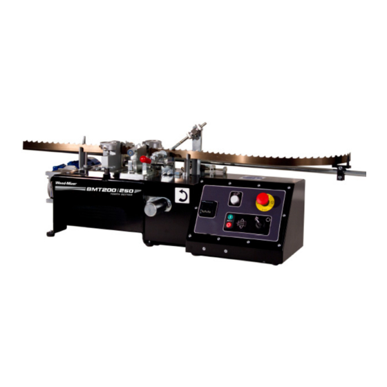
Introduction Dimensions and Specifications Dimensions and Specifications See Figure 1-1. . DS0002 74” (1880 mm) TOP VIEW 116 3/4” (2965 mm) 16 1/2” (419 mm) FRONT VIEW FIG. 1-1 Length Width Height Weight BMT200 74" (1880 mm) 116 3/4" (2965 mm) 16 1/2"... -
Page 8: Tooth Set Gauge
Tooth Set Gauge Calibration SECTION 2 TOOTH SET GAUGE Tooth Set Gauge Calibration 1. Insert the dial gauge assembly into the hole in the block housing. 2. Clamp the calibrating pin in position at the center of the dial gauge foot. 3. -
Page 9: Tooth Set Measurement
Tooth Set Measurement 8. Repeat the steps above until the dial needle reads zero with the calibrating clamped and between -0.005 and -0.010 without the pin clamped. 9. This insures the dial foot extends beyond the clamp plate a slight amount and will read zero when the foot is aligned with the clamp plate. -
Page 10: Setter Operation
SECTION 3 SETTER OPERATION Setter Alignment Wood-Mizer blades have a raker-style set in the teeth. If you look at a blade from the top, you will see that the teeth are set (bent out) in a repeating sequence; left, right, and straight. - Page 11 Setter Alignment For the manual setter, turn the feed handle counterclockwise; for automatic setters, set the feed switch to JOG (hand symbol) and press and hold the START button. START Manual START DS0018 FIG. 3-4 3. Insert the blade by looping it over the setter and positioning it between the posts of the blade support guides.
- Page 12 Setter Alignment 4. Adjust the blade height pins so the gullet of the tooth is positioned approximately flush with each setter clamp plate. SET GULLET FLUSH WITH CLAMP PLATE Clamp Blade height Plate adjustment knob FIG. 3- DS0001-47 5. Close the blade clamp handle and flip the index arm down into the blade (reverse Step 1.) 6.
- Page 13 Setter Alignment 9. On the right setter, adjust the blade until a "set-left" tooth is positioned just right of cen- ter in relation to the set block; close the blade clamp handle. SET-LEFT TOOTH JUST Index arm up RIGHT OF CENTER Set Block set-left Tooth...
- Page 14 Setter Alignment 13. Adjust the left setter assembly to match a "set-right" tooth by loosening the two mounting bolts and sliding the assembly. Mounting bolt Mounting bolt FIG. 3-9 DS0001-50 14. Retighten the bolts when the “set-right” tooth is aligned with the setter block. 15.
-
Page 15: The Setter Is Properly Aligned And Ready For The Calibration Process When
The setter is properly aligned and ready for the Calibration Process when: The setter is properly aligned and ready for the Calibration Process when: 1. The gullet of the blade is flush with the setter clamp plate. 2. The tooth of the blade is just right of center on the pusher block. DS0001-52 DS0001-53 3. -
Page 16: Setter Calibration
Setter Calibration IMPORTANT! The Setter needs to be aligned before calibration. Calibrating the BMT 200/250 is an essential step to ensure accurate setting of Wood-Mizer blades. Cutting performance is greatly increased using a blade that is accu- rately set. Calibrate with tooth set gauge 1. -
Page 17: Calibrate On The Setter
Calibrate on the setter 5. Before releasing the clamp, raise the rest pin to the bottom of the blade to create a refer- ence for the blade height. Rest pin Lock knob FIG. 4-13 SS0006-8 6. Count 5 teeth (for 7/8” & 1-1/8”tooth spacing) or 8 teeth (for 1/2”, 5/8”, & 3/4” tooth spac- ing) from the marked tooth. - Page 18 Calibrate on the setter 9. Clamp the blade. Reference tooth Reference tooth FIG. 4-15 DS0001-54 10. Adjust the knobs on the setter assemblies to back off the setter blocks completely. The blocks must be pushed in manually because they are not spring loaded. Be sure the blocks are backed off far enough so they will not contact the blade when you advance the blade in the next step.
- Page 19 Calibrate on the setter 12. Unlock the dial lock and adjust the setter gauge bezels so the needle of the gauges show the same tooth set measurements taken previously with the set master gauge. Setter Gauge Bezel Dial Lock FIG. 4-17 DS0001-38 Once the setter is calibrated you can now accurately adjust the set of the blade.
Need help?
Do you have a question about the BMT 200 and is the answer not in the manual?
Questions and answers