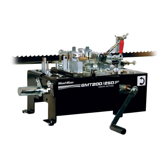
Wood-mizer BMT200 Safety, Operation, Maintenance & Parts Manual
Dual toothsetter
Hide thumbs
Also See for BMT200:
- Quick start manual (19 pages) ,
- Safety, operation, maintenance & parts manual (79 pages) ,
- Safety, operation, maintenance & parts manual (78 pages)
Table of Contents

Related Manuals for Wood-mizer BMT200


Summary of Contents for Wood-mizer BMT200
- Page 1 Dual Toothsetter Safety, Operation, Maintenance & Parts Manual BMT200 Rev. A.00 BMT250 Rev. A.00 Safety is our #1 concern! Read and understand all safety information and instructions before operating, setting up or maintaining this machine. Form #1792...
-
Page 2: Table Of Contents
................4-1 Every 3 Months ................4-2 Clamp Adjustment ................4-2 Gauge Assembly Adjustment ............... 4-3 Safety Devices Inspection ..................4-4 SECTION 5 STANDARD OPERATING PROCEDURE Setter alignment: BMT200/250 ................5-2 Calibration: BMT 200/250 .................. 5-6 DSdoc030819 Table of Contents... - Page 3 Table of Contents Section-Page SECTION 6 REPLACEMENT PARTS Dual Toothsetter (Complete)..................6-1 Dual Toothsetter Assembly ..................6-2 BMT200 Decals......................6-3 BMT250 Decals......................6-4 Base Housing Assembly.................... 6-5 Dual Toothsetter Right Head..................6-7 Dual Toothsetter Left Head ..................6-10 Index Shaft Assembly....................6-13 Blade Height Adjuster Assembly ................
-
Page 4: Section 1 Introduction
The information and instructions given in this manual do not amend or extend the limited warranties for the equipment given at the time of purchase. This equipment is designed to work with Wood-Mizer blades only. IMPORTANT! Read the entire Operator's Manual before operating the equipment. -
Page 5: General Contact Information
General Contact Information Getting Service Wood-Mizer is committed to providing you with the latest technology, best quality and strongest customer service available on the market today. We continually evaluate our customers’ needs to ensure we’re meeting current wood-processing demands. Your comments and suggestions are welcome. -
Page 6: Branches & Authorized Sales Centerswood-Mizer Locations (North And South America)1-3
Branches & Authorized Sales CentersWood-Mizer Locations (North and South America) Branches & Authorized Sales CentersWood-Mizer Locations (North and South America) EUROPE UNITED STATES European Headquarters World Headquarters Wood-Mizer Industries Sp. z o.o. Wood-Mizer LLC Nagórna 114, 62-600 Koło, Poland 8180 West 10th Street Tel.: +48-63-26-26-000 Indianapolis,Indiana 46214-2400, Fax: +48-63-27-22-327 www.woodmizer.eu... - Page 7 Branches & Authorized Sales CentersWood-Mizer Locations (North and South America) CROATIA Krešimir Pregernik ITALY Pasquale Felice SERBIA Dragan Markov Pregimex d.o.o. Wood-Mizer Italia Srl Wood-Mizer Balkan d.o.o. S. Batušiæa 31, 10090 Zagreb Cda. Capoiaccio SN Svetosavska GA 3/3; P. Fah 25 Tel.:/Fax: +3851-38-94-668...
- Page 8 Brazil Headquarters Europe Headquarters Serving Brazil Serving Europe, Africa, West Asia Wood-Mizer do Brasil Wood-Mizer Industries Sp z o.o. Rua Dom Pedro 1, No: 205 Bairro: Sao Jose Nagorna 114 Ivoti/RS CEP:93.900-000 62-600 Kolo, Poland Tel: +55 51 9894-6461/ +55 21 8030-3338/ +55 51 Phone: +48.63.26.26.000...
-
Page 9: Section 2 General Information
General Information Safety SECTION 2 GENERAL INFORMATION Safety This symbol calls your attention to instructions concerning your personal safety. Be sure to observe and follow these instructions. This symbol accompanies a signal word. The word DANGER indicates an imminently hazardous situation which, if not avoided, will result in death or serious injury. - Page 10 General Information Safety performing any service to the machine. Blade Handling WARNING! Always wear gloves and eye protection when handling bandsaw blades. Keep all persons away from area when coiling or carrying a blade. WARNING! Before installing the blade, inspect it for damage and cracks.
- Page 11 General Information Safety E-Stop button is released. General Information DSdoc030819...
- Page 12 General Information Safety Dual Toothsetter Decals See Table 2-1. The Dual Toothsetter decals are shown below. Decal Part Number Description S12004G Always wear safety goggles when operating the equipment! S12005G Always wear protective ear muffs when operating the equipment! 501465 Always wear safety boots when operating the equipment! 096319...
- Page 13 General Information Safety 096316 Do not open or close the electric box when the switch is not in the "0" position! Hand injury hazard 509255 509255 P85070 CE Certified Machine (Small) 053583 Dual Setter Operation Direction 053583 General Information DSdoc030819...
-
Page 14: Component Id
Blade Support Guide Blade Index Blade Assembly end Back Tool Clamp Auto Feed Motor* Blade Support Auto Feed Feed Crank Toothsetter Control* Handle Tooth Set Assemblies Master Gauge *Auto Feed: Optional for BMT200 Standard for BM&250 FIG. 2-1 DSdoc030819 General Information... -
Page 15: Dimensions And Specifications
FRONT VIEW FIG. 2-2 See Table 2-2. The overall dimensions and weight are listed below. Length Width Height Weight BMT200 74" (1880 mm) 116 3/4" (2965 mm) 16 1/2" (419 mm) 90 lbs. (41 kg) BMT250 74" (1880 mm) 116 3/4" (2965 mm) 16 1/2"... - Page 16 Voltage Electrical Electrical Description Package Code Standard Code BMT200 Dual Toothsetter w/Manual Crank BMT250 Automatic Dual Toothsetter (1 x 110V 60Hz) BMT250 Automatic Dual Toothsetter (1 x 230V 50Hz) M - 1 x 110V; A - 1 x 230V. U - UL (60Hz); S - CE (50Hz).
-
Page 17: Section 3 Setup & Operation
Setup & Operation Assembly SECTION 3 SETUP & OPERATION Assembly Place the setter on a table or workbench sturdy enough to support the weight of the machine. Be sure there is enough room on either side of the setter to allow for the blade to travel. - Page 18 Setup & Operation Assembly See Figure 3-2. Thread a blade support tube into the threaded holes in the three mounting blocks. Assemble a blade support extension tube to each blade support tube. NOTE: If installing the optional arm kit for heavier blades, assemble the blade support extension tubes to the extended mounting arms.
-
Page 19: Auto Feed Installation (Optional)
Setup & Operation Assembly Auto Feed Installation (Optional) The Auto Feed Option includes an electric motor and control to automate the setting process. See Figure 3-3. Before installing the Auto Feed, remove the manual feed crank handle. Disassemble the bolt, lock washer and fender washer to remove the handle. Remove the M10-1.25 x 20 hex head bolt, split lock washer and the shaft cover mounted to the left side of the setter assembly. - Page 20 Setup & Operation Assembly See Figure 3-4. Install the motor mount plate to the feed motor with six M5-.8 x 10 hex head bolts and #10 split lock washers. Feed Motor Feed Motor Motor Mount Plate Motor Mount Plate M5-0.8x10 Hex M5-.8 x 10 Hex Head Bolt (6) Head Bolt (6)
- Page 21 Setup & Operation Assembly See Figure 3-6. Set the Auto Feed control box near the setter at a convenient operating location. Secure the motor harness with wire ties as necessary. Index Arm Proximity Sensor Motor Wire Tie Auto Feed Control Box Proximity Sensor Cable Motor Harness FIG.
-
Page 22: Operation
Setup & Operation Operation Operation Blade Installation/Setup WARNING! Always wear gloves and eye protection when handling bandsaw blades. Changing blades is safest when done by one person! Keep all other persons away from area when coiling, carrying or changing a blade. Failure to do so may result in serious injury. - Page 23 Setup & Operation Operation See Figure 3-8. Pull the blade clamp lever open and flip the index arm up. Turn the feed handle counterclockwise (or push and hold the Auto Feed option START - JOG button) to advance the setter until the setter assemblies open. WARNING! Before installing the blade, inspect it for dam- age and cracks.
- Page 24 Setup & Operation Operation See Figure 3-9. Loosen the wing nut on each blade support guide and adjust so the blade is positioned between the support posts. Tilt the guide slightly forward in the direc- tion the blade travels and retighten the wing nut. Make sure the blade support does not lift the blade.
- Page 25 Setup & Operation Operation See Figure 3-10. Adjust the blade height adjustment pins so the gullet of the blade is positioned approximately 1/16" below each setter clamp plate. Push the clamp handle closed and flip the index arm down onto the blade. Blade Height Blade Height Blade Height...
- Page 26 Setup & Operation Operation See Figure 3-11. Check the position of the rear-set tooth in relation to the right setter block. The tooth should be centered with the block. Turn the adjustment knobs on the index arm if necessary so that rear-set tooth is centered with the setter block. Push the clamp handle closed.
- Page 27 Setup & Operation Operation See Figure 3-12. Continue advancing the setter to index the blade to the next set of teeth. Stop the setter when the setter assemblies are completely closed. Turn the setter block adjustment knobs until the blocks just contact the blade teeth. Advance the setter to open the setter assemblies and turn the setter block adjustment knobs a few more turns.
-
Page 28: Manual Feed Operation
Setup & Operation Operation Manual Feed Operation WARNING! Always wear eye protection when operating the setter. Failure to do so may result in serious injury. Turn the feed handle clockwise to advance the setter until the setter assemblies open. Pull the clamp handle open and rotate the blade around the setter until the blade weld is positioned to the left of the left setter assembly. -
Page 29: Auto Feed Operation
NOTE: Most blades manufactured by Wood-Mizer are made so the set pattern across the weld is consistent with the rest of the blade. - Page 30 The display value will increase as the blade passes through and the setter will stop when the display matches the counter value. IMPORTANT: When setting Wood-Mizer blades with a raker-style pattern (one tooth bent left, one bent right and a straight tooth) the counter display should increment in multiples of three.
-
Page 31: Dual Setter Calibration
Setup & Operation Dual Setter Calibration Dual Setter Calibration WARNING! Always wear gloves and eye protection when handling bandsaw blades. Changing blades is safest when done by one person! Keep all other persons away from area when coiling, carrying or changing a blade. Failure to do so may result in serious injury. -
Page 32: Dual Setter Calibration
Setup & Operation Dual Setter Calibration Dual Setter Calibration See Figure 3-15. Pull the blade clamp lever open and flip the index arm up. Turn the feed handle counterclockwise (or push and hold the Auto Feed option START - JOG button) to advance the setter until the setter assemblies open. - Page 33 Setup & Operation Dual Setter Calibration See Figure 3-16. Place the set master gauge around the blade to measure tooth set. Turn the lock knob counterclockwise to loosen and adjust the blade height rest pin up or down. Adjust so when the blade rests on the pin, the gullet of the blade is just below the clamp plate.
- Page 34 Setup & Operation Dual Setter Calibration See Figure 3-17. Position the blade so that the teeth measured with the set master gauge are located in the left and right setter assemblies. Adjust the blade height adjust- ment pins so the gullet of the blade is positioned approximately 1/16" below each setter clamp plate.
-
Page 35: Section 4 Maintenance
Maintenance Routine Maintenance Schedule SECTION 4 MAINTENANCE WARNING! Always turn off and disconnect power at control console AND at main supply circuit breaker before performing any service to the machine. Routine Maintenance Schedule See Figure 4-1. Maintenance items referenced in the instructions below. FIG. -
Page 36: Every 3 Months
Setup & Operation Routine Maintenance Schedule Every 3 Months Lubricate the index arm pivot (D) and the feed shaft bearings (E). Apply NLGI No. 2 grade lithium grease to the grease fittings. Check the setter blocks (F) and clamp pads (G) for wear. If the top edge of the clamp pad is worn, remove the mounting screw and rotate the pad 90°... -
Page 37: Gauge Assembly Adjustment
Setup & Operation Routine Maintenance Schedule Gauge Assembly Adjustment The gauge assemblies are installed and properly adjusted at the factory. If it is necessary, use the gauge strip to adjust the gauge assemblies as described below. Pull the blade clamp lever open and flip the index arm up. Turn the feed handle counterclockwise (or push and hold the Auto Feed option START - JOG button) to advance the setter until the setter assemblies open. -
Page 38: Safety Devices Inspection
Setup & Operation Safety Devices Inspection Safety Devices Inspection Auto Feed Option Only: Check the Emergency Stop (E-Stop) button for proper operation every shift. See Figure 4-4. The Emergency Stop (E-Stop) and START buttons as shown below. Emergency Stop Emergency Stop (E-Stop) Button (E-Stop) Button START Button... -
Page 39: Section 5 Standard Operating Procedure
SECTION 5 STANDARD OPERATING PROCEDURE... -
Page 40: Setter Alignment: Bmt200/250
PERATING ROCEDURE The blades supplied by Wood-Mizer have a raker-style set in the teeth. If you look at a blade from the top, you will see that the teeth are set (or bent out) in a repeating sequence; left, right, and straight. The teeth that are set left and right do the cutting. The straight teeth (rakers) clear the cut of sawdust. -
Page 41: Setter Alignment: Bmt200/250
BMT200/250 ETTER LIGNMENT TANDARD PERATING ROCEDURE 3. To insert blade, loop the blade over the setter and position it between the posts of the blade support guides. Place the blade between the clamp rollers and between the setter blocks, resting on the blade height adjustment pins. - Page 42 BMT200/250 ETTER LIGNMENT TANDARD PERATING ROCEDURE 6. While holding the index arm so it does not push the blade forward, advance the setter until the index arm has advanced as far is it can go. Drop the index arm onto the blade and adjust the index arm(Figure 6.1) so it is tight in the gullet of the tooth.
- Page 43 BMT200/250 ETTER LIGNMENT TANDARD PERATING ROCEDURE Warning: before attempting to set a blade, perform the Setter Calibration process to make sure that the gauge assemblies are adjusted properly. The setter is properly aligned and ready for the Calibration Process when: 1.
-
Page 44: Calibration: Bmt 200/250
The Setter needs to be properly aligned before calibration. Refer to the Setter Alignment SOP Calibrating the BMT 200/250 is an essential step to ensure correct and acurate setting of the Wood-Mizer blades. The cutting performance will be greatly increased with a blade that has been accurately set. - Page 45 BMT 200/250 ALIBRATION TANDARD PERATING ROCEDURE 5. Bring the blade back to the setter machine and align the marked teeth with the setter assemblies. Clamp the blade. 6. Adjust the knobs on the setter assemblies to back off the setter blocks completely, the blocks will have to be pushed in manually because they are not spring loaded.
- Page 46 BMT 200/250 ALIBRATION TANDARD PERATING ROCEDURE Once the setter is calibrated you can now accurately adjust the set of the blade. Use the “tabs” on the gauges to bracket the desired set. Typical Deviation allowed is two thousandths. Desired set: 21 (Tolerance 19 - 23) To adjust the set of the blade to your desired set, adjust the knob on the setter assembly to bring the setter block in.
-
Page 47: Section 6 Replacement Parts
Replacement Parts Dual Toothsetter (Complete) SECTION 6 REPLACEMENT PARTS Dual Toothsetter (Complete) REF. DESCRIPTION ( Indicates Parts Available in Assemblies Only) PART # DUAL TOOTHSETTER PARTS (See Section 6.2) 524510 ELECTRIC BOX PARTS, OPTIONAL AUTOMATIC FEED (See Section 6.18) 525267 MOTOR PARTS, OPTIONAL AUTOMATIC FEED (See Section 6.15) -
Page 48: Dual Toothsetter Assembly
Replacement Parts Dual Toothsetter Assembly Dual Toothsetter Assembly REF. DESCRIPTION ( Indicates Parts Available in Assemblies Only) PART # TOOTHSETTER ASSEMBLY, DUAL 524510 Base Housing Assembly (See Section 6.5) Dual Toothsetter Right Head (See Section 6.6) 524535 Dual Toothsetter Left Head (See Section 6.7) 524536... -
Page 49: Bmt200 Decals
Replacement Parts BMT200 Decals BMT200 Decals REF. DESCRIPTION ( Indicates Parts Available in Assemblies Only) PART # DECAL KIT, BMT200 525332 DECAL, "USE PROTECTIVE GLOVES" (PICTOGRAM) 512107 DECAL, "USE SAFETY GOGGLES" (PICTOGRAM) S12004G-1 DECAL, "USE SAFETY BOOTS" (PICTOGRAM) 501465 DECAL, HAND INJURY HAZARD (PICTOGRAM) 509255 DECAL, READ OPERATOR’S MANUAL (PICTOGRAM) -
Page 50: Bmt250 Decals
Replacement Parts BMT250 Decals BMT250 Decals REF. DESCRIPTION ( Indicates Parts Available in Assemblies Only) PART # DECAL KIT, BMT250 526834 DECAL, "USE PROTECTIVE GLOVES" (PICTOGRAM) 512107 DECAL, "USE SAFETY GOGGLES" (PICTOGRAM) S12004G-1 DECAL, "USE SAFETY BOOTS" (PICTOGRAM) 501465 DECAL, HAND INJURY HAZARD (PICTOGRAM) 509255 DECAL, READ OPERATOR’S MANUAL (PICTOGRAM) -
Page 51: Base Housing Assembly
Replacement Parts Base Housing Assembly Base Housing Assembly REF. DESCRIPTION ( Indicates Parts Available in Assemblies Only) PART # TOOTHSETTER, BMT200-P DUAL 524510 BASE WELDMENT, DUAL TOOTHSETTER 524511-1 GUARD, DRIVE SHAFT - COMPLETE 525254 GUARD, DRIVE SHAFT ZINC-PLATED 525255-1 BOLT, M10X16-8.8 HEX HEAD FULL THREAD ZINC... - Page 52 Replacement Parts Base Housing Assembly REF. DESCRIPTION ( Indicates Parts Available in Assemblies Only) PART # COVER, LOWER 525262-1 WASHER, 6.4 FLAT ZINC F81053-1 NUT, M6-8-B HEX NYLON ZINC LOCK F81031-2 BOLT, M6X20 8.8 HEX HEAD FULL THREAD ZINC F81001-2 FOOT, SR 1591 25.3X12.5 (MOSS 34363) 515250 DSdoc030819...
-
Page 53: Dual Toothsetter Right Head
Replacement Parts Dual Toothsetter Right Head Dual Toothsetter Right Head REF. DESCRIPTION (* Indicates Parts Available in Assemblies Only) PART # HEAD, DUAL TOOTHSETTER RIGHT - COMPLETE 524535 PLATE, HEAD BASE ZINC-PLATED 524516-1 ARM, DUAL TOOTHSETTER - COMPLETE 524520 ARM, DUAL TOOTHSETTER ZINC-PLATED 524521-1 BEARING, 6000.2RSR 087471... - Page 54 Replacement Parts Dual Toothsetter Right Head REF. DESCRIPTION (* Indicates Parts Available in Assemblies Only) PART # PLATE, PUSHER ARM SIDE ZINC-PLATED 524525-1 WASHER, 20.5X26X1.5 ZINC-PLATED 524526-1 BEARING, 6004 2RS CX ROLLING 093868 PLATE, SPRING ZINC-PL. ADJUSTMENT 524515-1 SPRING, 3/4 OD X 1-1/2 L X .165X.125 WIRE DIE 060499 BOLT, PUSHER ADJUSTMENT 524531...
- Page 55 Replacement Parts Dual Toothsetter Right Head REF. DESCRIPTION (* Indicates Parts Available in Assemblies Only) PART # SCREW, M10X55-8.8 HEX SOCKET HEAD CAP ZINC F81003-55 SCREW, GN 913.5-M6-12-KU (ELESA+GANTER) STAINLESS STEEL F81001-78 BOLT, DIN933-M10X30-8.8-A2E HEX HEAD F81003-111 Replacement Parts DSdoc030819...
-
Page 56: Dual Toothsetter Left Head
Replacement Parts Dual Toothsetter Left Head Dual Toothsetter Left Head REF. DESCRIPTION (* Indicates Parts Available in Assemblies Only) PART # HEAD, DUAL TOOTHSETTER LEFT - COMPLETE 524536 PLATE, HEAD BASE ZINC-PLATED. 524516-1 ARM, DUAL TOOTHSETTER - COMPLETE 524520 6-10 DSdoc030819 Replacement Parts... - Page 57 Replacement Parts Dual Toothsetter Left Head REF. DESCRIPTION (* Indicates Parts Available in Assemblies Only) PART # ARM, DUAL TOOTHSETTER ZINC-PLATED 524521-1 BEARING, 6000.2RSR 087471 RING, W26 INSIDE RETAINING F81090-34 WASHER, 10.2X16X4 ZINC-PLATED SPACER 524529-1 BLOCK, ZINC-PLATED SUPPORT 524528-1 PLATE, PUSHER ARM SIDE ZINC-PLATED 524525-1 WASHER, 20.5X26X1.5 ZINC-PLATED 524526-1...
- Page 58 Replacement Parts Dual Toothsetter Left Head REF. DESCRIPTION (* Indicates Parts Available in Assemblies Only) PART # GAUGE ASSEMBLY, TOOTH SET 524539 BRACKET, GAUGE MOUNT ZINC-PLATED 524540-1 INSERT, SETTER CLAMPING STL (METRIC) 066609 GAUGE ASSEMBLY, TOOTHSETTER 061771 SCREW, M5X16-8.8 DIN7991 FLAT SOCKET HEAD CAP ZINC F81000-47 SCREW, M10X55-8.8 HEX SOCKET HEAD CAP ZINC F81003-55...
-
Page 59: Index Shaft Assembly
Index Shaft Assembly Index Shaft Assembly REF. DESCRIPTION (* Indicates Parts Available in Assemblies Only) PART # SHAFT, INDEX - COMPLETE 524547 SHAFT, INDEX ZINC-PLATED 524548-1 GEAR, 10 PITCH X 2.5 PITCH DIAX3/4" BORE 060565 BUSHING, AMES B 25X30X25/35 FLANGED 524555 KEY, A 6X6X22 PARALLEL 519161... - Page 60 Index Shaft Assembly REF. DESCRIPTION (* Indicates Parts Available in Assemblies Only) PART # BEARING, 6004 2RS CX ROLLING 093868 WASHER, 20.5 SPLIT LOCK ZINC F81059-1 BOLT, M20X40-8.8 HEX HEAD FULL THREAD ZINC F81007-11 WASHER, 8.2 SPLIT LOCK ZINC F81054-4 BOLT, M8X20 8.8 HEX HEAD FULL THREAD ZINC F81002-4 SCREW, M8X30-8.8 HEX SOCKET HEAD CAP ZINC...
-
Page 61: Blade Height Adjuster Assembly
Replacement Parts Blade Height Adjuster Assembly Blade Height Adjuster Assembly REF. DESCRIPTION (* Indicates Parts Available in Assemblies Only) PART # ADJUSTER ASSEMBLY, BLADE HEIGHT 524558 SHAFT, BLADE HEIGHT ADJUSTER ZINC-PLATED 524559-1 KEY, A 6X6X22 PARALLEL 519161 BUSHING, AMES B 18X22X18/26 FLANGED 524556 WASHER, ISO 7093-1-8-200 HV-A2E F81054-11... -
Page 62: Blade Clamp & Guide
Replacement Parts Blade Clamp & Guide 6.10 Blade Clamp & Guide REF. DESCRIPTION (* Indicates Parts Available in Assemblies Only) PART # BLADE CLAMP & GUIDE - COMPLETE 524564 BAR WELDMENT, CLAMP BASE ZINC-PLATED 524565-1 BAR, CLAMP BASE 524566 CLAMP, BLADE - COMPLETE 524578 BLOCK, CLAMP ZINC-PLATED MOUNTING 524571-1... - Page 63 Replacement Parts Blade Clamp & Guide REF. DESCRIPTION (* Indicates Parts Available in Assemblies Only) PART # WASHER, 10.5 FLAT ZINC F81055-1 PLATE, BEARING BLOCK GUIDE ZINC-PLATED 524577-1 WASHER, ISO 7093-1-8-200 HV-A2E F81054-11 WASHER, 3/8 X 13/16 X .093 RUBBER 060531 BOLT, M6X20 8.8 HEX HEAD FULL THREAD ZINC F81001-2...
-
Page 64: Outfeed Blade Guide
Replacement Parts Outfeed Blade Guide 6.11 Outfeed Blade Guide REF. DESCRIPTION (* Indicates Parts Available in Assemblies Only) PART # GUIDE, BLADE OUTFEED - COMPLETE 525245 GUIDE WELDMENT, BLADE OUTFEED ZINC-PLATED 525246-1 WASHER, 6.5 SPECIAL FLAT ZINC F81053-11 WASHER, Z 6.1 SPLIT LOCK ZINC F81053-3 BOLT, M6X20 8.8 HEX HEAD FULL THREAD ZINC F81001-2... -
Page 65: Optional Tool Set
Replacement Parts Optional Tool Set 6.12 Optional Tool Set REF. DESCRIPTION (* Indicates Parts Available in Assemblies Only) PART # TOOL SET, OPTIONAL - COMPLETE 525275 BRACKET, TOOL SET ZINC-PLATED 525274-1 PIN, DOWELL 3/8 X 2 1/4 HARDENED F05012-106 BOLT, M6X12 8.8 HEX HEAD FULL THREAD ZINC F81001-7 TOOL, BEND BACK 023774... -
Page 66: Blade Support Arm
Replacement Parts Blade Support Arm 6.13 Blade Support Arm REF. DESCRIPTION (* Indicates Parts Available in Assemblies Only) PART # ARM, BLADE SUPPORT - COMPLETE 525263 TUBE, BLADE SUPPORT ZINC-PLATED 525320-1 BLOCK 522462-1 BLOCK 522461-1 WASHER, Z 10.2 SPLIT LOCK ZINC F81055-2 BUSHING, 11/20-17 ZINC-PLATED 094255-1... -
Page 67: Tooth Set Gauge Assembly
Replacement Parts Tooth Set Gauge Assembly 6.14 Tooth Set Gauge Assembly SS0006-2B REF. DESCRIPTION ( Indicates Parts Available In Assemblies Only) PART # GAUGE ASSEMBLY, TOOTH SET BOXED 060490 Block, Tooth Set Gauge 060495 Plate, Tooth Set Clamp 060494 Screw, #8-32 x 1 1/4" Socket Head F05004-225 Screw, 1/4-20 x 1/4"... -
Page 68: Side Blade Guide
Replacement Parts Side Blade Guide 6.15 Side Blade Guide REF. DESCRIPTION ( Indicates Parts Available In Assemblies Only) PART # GUIDE, SIDE BLADE - COMPLETE 527137 BASE, BLADE GUIDE ZINC-PLATED 525323-1 CHANNEL, CLAMPING ZINC-PLATED 525328-1 CHANNEL, BLADE GUIDE ZINC-PLATED 525330-1 WASHER, 8.4 FLAT ZINC F81054-1 KNOB, SR.40/M8X20 STAR (462053 MOSS) -
Page 69: Rear Blade Guide
Replacement Parts Rear Blade Guide 6.16 Rear Blade Guide REF. DESCRIPTION ( Indicates Parts Available In Assemblies Only) PART # GUIDE, REAR BLADE - COMPLETE 525322 BASE, BLADE GUIDE ZINC-PLATED 525323-1 BRACKET, BLADE GUIDE ROLLER ZINC-PLATED 525325-1 CHANNEL, CLAMPING ZINC-PLATED 525328-1 CHANNEL, BLADE GUIDE ZINC-PLATED 525330-1... - Page 70 Replacement Parts Rear Blade Guide REF. DESCRIPTION ( Indicates Parts Available In Assemblies Only) PART # NUT, M10-8-B HEX NYLON ZINC LOCK F81033-1 SCREW, M10X40-8.8 HEX SOCKET HEAD CAP ZINC F81003-22 NUT, M8-8-B HEX ZINC F81032-1 BEARING, 608 2RS BALL 086197 6-24 DSdoc030819...
-
Page 71: Bmt250 Toothsetter Drive
Replacement Parts BMT250 Toothsetter Drive 6.17 BMT250 Toothsetter Drive REF. DESCRIPTION ( Indicates Parts Available In Assemblies Only) PART # DRIVE, BMT250 120/230V TOOTHSETTER - COMPLETE 525265 MOTOREDUCER, MRA-03/39/0,12-1400/B8 508440 MOTOR, SKH-63-4A2, 012 KW,1400, UL, CE 508441 PLATE, MOTOREDUCER ZINC-PLATED MOUNT 525266-1 WASHER, 5.1 SPLIT LOCK ZINC F81052-2... -
Page 72: Toothsetter Control Box
Replacement Parts Toothsetter Control Box 6.18 Toothsetter Control Box REF. DESCRIPTION ( Indicates Parts Available In Assemblies Only) PART # BOX, AC120/230V TOOTHSETTER CONTROL 525267 BOX, BMT250 TOOTHSETTER CONTROL 525268-1 FOOT, SR1591 12X6 #50185 MOSS 101279 PLATE, CONTROL BOX ZINC-PLATED MOUNT 525273-1 SWITCH, I/O ROCKER 060515... - Page 73 Replacement Parts Toothsetter Control Box REF. DESCRIPTION ( Indicates Parts Available In Assemblies Only) PART # BOLT, #10-24X1/2 PH F05015-17 GLAND, DP 7/H CABLE F81096-11 GLAND, PG11 CABLE F81096-9 Replacement Parts DSdoc030819 6-27...
- Page 74 EC declaration of conformity according to EC Machinery Directive 2006/42/EC We herewith declare, Wood-Mizer Industries Sp. z o.o. 114 Nagórna street, 62- o; Poland. That the following described machine in our delivered version complies with the appropriate basic safety and health requirements of the EC Machinery Directive 2006/42/EC based on its design and type, as brought into circulation by us.
Need help?
Do you have a question about the BMT200 and is the answer not in the manual?
Questions and answers