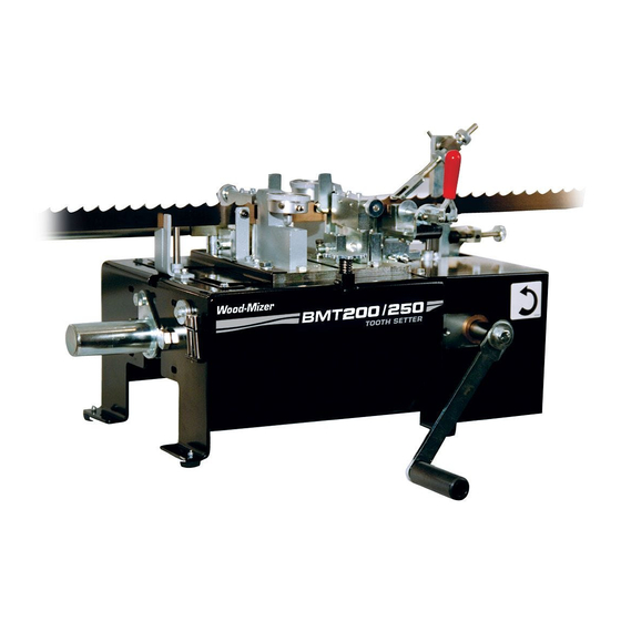
Wood-mizer BMT200 Safety, Operation, Maintenance & Parts Manual
Dual toothsetter
Hide thumbs
Also See for BMT200:
- Safety, operation, maintenance & parts manual (74 pages) ,
- Quick start manual (19 pages) ,
- Safety, operation, maintenance & parts manual (78 pages)
Table of Contents
Advertisement
Quick Links
Advertisement
Table of Contents

Related Manuals for Wood-mizer BMT200


Summary of Contents for Wood-mizer BMT200
- Page 1 Dual Toothsetter Safety, Operation, Maintenance & Parts Manual BMT200 Rev. A.00 - A.02 BMT250 Rev. A.00 - A.02 Safety is our #1 concern! Read and understand all safety information and instructions before oper- ating, setting up or maintaining this machine.
-
Page 2: Table Of Contents
Table of Contents Section-Page SECTION 1 INTRODUCTION About This Manual....................1-1 Getting Service ......................1-2 General Contact Information.............. 1-2 Wood-Mizer Locations................ 1-3 SECTION 2 GENERAL INFORMATION Safety......................... 2-1 Component ID ......................2-5 Dimensions and Specifications.................. 2-6 SECTION 3 SETUP & OPERATION Assembly ........................ - Page 3 Table of Contents Section-Page SECTION 5 REPLACEMENT PARTS Dual Toothsetter (Complete)..................5-1 Dual Toothsetter Assembly ..................5-2 Base Housing Assembly.................... 5-3 Feed Drive Assembly ....................5-5 Blade Setters......................5-7 Blade Set Arm Assembly ..................5-9 Clamp Assembly ..................... 5-11 Index Assembly ....................... 5-13 Blade Support Arm Assembly.................
-
Page 4: Introduction
The information and instructions given in this manual do not amend or extend the limited warranties for the equipment given at the time of purchase. This equipment is designed to work with Wood-Mizer blades only. IMPORTANT! Read the entire Operator's Manual before operating the equipment. -
Page 5: Getting Service
Introduction Getting Service Getting Service Wood-Mizer is committed to providing you with the latest technology, best quality and strongest customer service available on the market today. We continually evaluate our customers’ needs to ensure we’re meeting current wood-processing demands. Your comments and suggestions are welcome. -
Page 6: Wood-Mizer Locations
Brazil Headquarters Europe Headquarters Serving Brazil Serving Europe, Africa, West Asia Wood-Mizer do Brasil Wood-Mizer Industries Sp z o.o. Rua Dom Pedro 1, No: 205 Bairro: Sao Jose Nagorna 114 Ivoti/RS CEP:93.900-000 62-600 Kolo, Poland Tel: +55 51 9894-6461/ +55 21 8030-3338/ +55 51 Phone: +48.63.26.26.000... -
Page 7: General Information
General Information Safety SECTION 2 GENERAL INFORMATION Safety This symbol calls your attention to instructions concerning your personal safety. Be sure to observe and follow these instructions. This symbol accompanies a signal word. The word DANGER indicates an imminently hazardous situation which, if not avoided, will result in death or serious injury. - Page 8 General Information Safety Blade Handling WARNING! Always wear gloves and eye protection when handling bandsaw blades. Keep all persons away from area when coiling or carrying a blade. WARNING! Before installing the blade, inspect it for dam- age and cracks. Always handle the blade with extreme care.
- Page 9 General Information Safety Dual Toothsetter Decals See Table 2-1. The Dual Toothsetter decals are shown below. Decal Part Number Description 069680 WARNING! Secure all loose clothing and jewelry before operating this machine. Fail- ure to do so may result in serious injury or death.
- Page 10 General Information Safety 069682 DANGER! HAZARDOUS VOLTAGE can cause shock, burns, or death. SHUT OFF & LOCK OUT POWER before performing ser- vice in any area of this machine. DO NOT restore power until all access panels are replaced and secured. 069682 069685 WARNING! Read the entire Operator's...
-
Page 11: Component Id
Guide Blade Index Blade Assembly Clamp Bend Back Tool Auto Feed Motor* Blade Support Auto Feed Feed Crank Toothsetter Control* Handle Assemblies Tooth Set Master Gauge DS0001-14 *Auto Feed: Optional for BMT200 Standard for BMT250 FIG. 2-1 General Information DS12doc060917... -
Page 12: Dimensions And Specifications
FRONT VIEW FIG. 2-2 See Table 2-2. The overall dimensions and weight are listed below. Length Width Height Weight BMT200 74" (1880 mm) 116 3/4" (2965 mm) 16 1/2" (419 mm) 90 lbs. (41 kg) BMT250 74" (1880 mm) 116 3/4" (2965 mm) 16 1/2"... - Page 13 Voltage Electrical Electrical Description Standard Package Code Code BMT200 Dual Toothsetter w/Manual Crank BMT250 AC Automatic Dual Toothsetter (1 x 110V 60Hz) BMT250 AC Automatic Dual Toothsetter (1 x 230V 50Hz) BMT250 DC Automatic Dual Toothsetter (1 x 110-230V 50/60Hz) M - 1 x 110V;...
- Page 14 General Information Dimensions and Specifications Interrupter (GFI) be used. DS12doc060917 General Information...
-
Page 15: Setup & Operation
Setup & Operation Assembly SECTION 3 SETUP & OPERATION Assembly Place the setter on a table or workbench sturdy enough to support the weight of the machine. Be sure there is enough room on either side of the setter to allow for the blade to travel. - Page 16 Setup & Operation Assembly See Figure 3-2. Thread a blade support tube into the threaded holes in the three mount- ing blocks. Assemble a blade support extension tube to each blade support tube. NOTE: If installing the optional arm kit for heavier blades, assemble the blade support extension tubes to the extended mounting arms.
-
Page 17: Auto Feed Installation (Optional - Ac Only)
Setup & Operation Assembly Auto Feed Installation (Optional - AC Only) The AC Auto Feed Option includes an electric motor and control to automate the setting process. See Figure 3-3. Before installing the Auto Feed, remove the manual feed crank handle. Disassemble the bolt, lock washer and fender washer to remove the handle. - Page 18 Setup & Operation Assembly See Figure 3-4. Install two 5 x 5 x 25mm round end keys to the feed shaft and slide the motor with the mount plate onto the feed shaft. Secure the motor to the setter base. M8 Hex Nylon Nut (4) 5 x 5 x 25mm Round End Key (2)
- Page 19 Setup & Operation Assembly See Figure 3-5. Set the Auto Feed control box near the setter at a convenient operating location. Secure the motor harness with wire ties as necessary. Index Arm 2-3mm Motor Proximity Sensor Wire Tie Auto Feed Proximity Sensor Cable DS0001-19 Motor Harness...
-
Page 20: Auto Feed Installation (Optional - Dc Only)
Setup & Operation Assembly Auto Feed Installation (Optional - DC Only) The DC Auto Feed Option includes an electric motor and control to automate the setting process. See Figure 3-6. Before installing the Auto Feed, remove the manual feed crank handle. Disassemble the bolt, lock washer and fender washer to remove the handle. - Page 21 Setup & Operation Assembly See Figure 3-7. Remove the existing shaft end bolts from the setter. Install the feed motor mount bracket around the feed shaft and secure with the provided shaft end bolts, flat washers and existing nylon lock nuts. Leave the bolts slightly loose until the motor is pinned to the feed shaft as described later.
- Page 22 Setup & Operation Assembly See Figure 3-9. Slide the sleeve and motor assembly onto the feed shaft and secure to the motor mount bracket with four flat washers, lock washers, hex head bolts and self-locking nuts. Leave the bolts slightly loose until the motor is pinned to the feed shaft as described later.
- Page 23 Setup & Operation Assembly See Figure 3-11. Set the Auto Feed control box near the setter at a convenient operating location. Connect the motor harnesses with two-pin connectors together. Secure the motor harness with wire ties as necessary. Motor Harness DS0013-2B Sensor Ground Wire...
-
Page 24: Operation
Setup & Operation Operation Operation Blade Installation/Setup WARNING! Always wear gloves and eye protection when handling bandsaw blades. Changing blades is safest when done by one person! Keep all other persons away from area when coiling, carrying or changing a blade. Failure to do so may result in serious injury. - Page 25 Setup & Operation Operation Start - Jog Button Power On/Off Pilot Light Counter DS0016 Auto/Manual Stop Button Toggle Switch Control Box Front Control Box Rear FIG. 3-12 DC ONLY WARNING! AC Only: If at any time you need to immedi- ately stop the machine, press the Emergency Stop (E-Stop) button.
- Page 26 Setup & Operation Operation See Figure 3-13. Pull the blade clamp lever open and flip the index arm up. Turn the feed handle counterclockwise (or push and hold the Auto Feed option START - JOG button) to advance the setter until the setter assemblies open. WARNING! Before installing the blade, inspect it for dam- age and cracks.
- Page 27 Setup & Operation Operation See Figure 3-14. Loosen the wing nut on each blade support guide and adjust so the blade is positioned between the support posts. Tilt the guide slightly forward in the direc- tion the blade travels and retighten the wing nut. Make sure the blade support does not lift the blade.
- Page 28 Setup & Operation Operation See Figure 3-15. Adjust the blade height adjustment pins so the gullet of the blade is positioned approximately 1/16" below each setter clamp plate. Push the clamp handle closed and flip the index arm down onto the blade. NOTE: Use the 3/8" x 2 1/4" blade height adjustment pins (F05012-106) for 2"-3"...
- Page 29 Setup & Operation Operation See Figure 3-16. Check the position of the rear-set tooth in relation to the right setter block. The tooth should be centered with the block. Turn the adjustment knobs on the index arm if necessary so that rear-set tooth is centered with the setter block. Push the clamp handle closed.
- Page 30 Setup & Operation Operation See Figure 3-17. Continue advancing the setter to index the blade to the next set of teeth. Stop the setter when the setter assemblies are completely closed. Turn the setter block adjustment knobs until the blocks just contact the blade teeth. Advance the setter to open the setter assemblies and turn the setter block adjustment knobs a few more turns.
-
Page 31: Manual Feed Operation
Setup & Operation Operation Advance the setter to index the blade to the next set of teeth. Continue advancing the set- ter until the setter blocks bend the teeth and indexes to the next set of teeth. Use the sup- plied gauge to measure the set of both the rear-set and forward-set teeth. -
Page 32: Auto Feed Operation
NOTE: Most blades manufactured by Wood-Mizer are made so the set pattern across the weld is consistent with the rest of the blade. - Page 33 When done setting blades, toggle the power ON/OFF switch on the back of the control box to the OFF (O) position. NOTE: The MODE button is used only to configure the counter settings for Wood-Mizer application.
-
Page 34: Dual Setter Calibration
Setup & Operation Dual Setter Calibration Dual Setter Calibration WARNING! Always wear gloves and eye protection when handling bandsaw blades. Changing blades is safest when done by one person! Keep all other persons away from area when coiling, carrying or changing a blade. Failure to do so may result in serious injury. - Page 35 Setup & Operation Dual Setter Calibration Dual Setter Calibration See Figure 3-21. Pull the blade clamp lever open and flip the index arm up. Turn the feed handle counterclockwise (or push and hold the Auto Feed option START - JOG button) to advance the setter until the setter assemblies open.
- Page 36 Setup & Operation Dual Setter Calibration See Figure 3-22. Place the set master gauge around the blade to measure tooth set. Turn the lock knob counterclockwise to loosen and adjust the blade height rest pin up or down. Adjust so when the blade rests on the pin, the gullet of the blade is just below the clamp plate.
- Page 37 Setup & Operation Dual Setter Calibration See Figure 3-24. Turn the clamp knob clockwise to securely clamp the blade and read the set measurement displayed by the set master gauge. Note the tooth set measure- ment and mark the measured tooth with a marker. Read set Tooth set back toward gauge...
- Page 38 Setup & Operation Dual Setter Calibration NOTE: The setter is factory-set for blades with 7/8" tooth spacing. Once a rear-set tooth is indexed in front of the right setter block, a forward-set tooth should be positioned in front of the left setter block. To adjust the setter for different tooth spacing, loosen the left setter mounting bolts and slide the assembly to position the setter block behind a for- ward-set tooth.
- Page 39 Setup & Operation Dual Setter Calibration See Figure 3-27. Unlock the dial lock and adjust the setter gauge bezels so the needles of the setter gauges show the same tooth set measurements taken previously with the set master gauge. Setter Gauge Bezel Dial Lock DS0001-38...
-
Page 40: Maintenance
Maintenance Routine Maintenance Schedule SECTION 4 MAINTENANCE WARNING! Always turn off and disconnect power at control console AND at main supply circuit breaker before perform- ing any service to the machine. Routine Maintenance Schedule See Figure 4-1. Maintenance items referenced in the instructions below. DS0001-29 FIG. -
Page 41: Every 3 Months
Setup & Operation Routine Maintenance Schedule Every 3 Months Lubricate the index arm pivot (D) and the feed shaft bearings (E). Apply NLGI No. 2 grade lithium grease to the grease fittings. Check the setter blocks (F) and clamp pads (G) for wear. If the top edge of the clamp pad is worn, remove the mounting screw and rotate the pad 90°... -
Page 42: Gauge Assembly Adjustment
Setup & Operation Routine Maintenance Schedule Gauge Assembly Adjustment The gauge assemblies are installed and properly adjusted at the factory. If it is necessary, use the gauge strip to adjust the gauge assemblies as described below. Pull the blade clamp lever open and flip the index arm up. Turn the feed handle counter- clockwise (or push and hold the Auto Feed option START - JOG button) to advance the setter until the setter assemblies open. -
Page 43: Safety Devices Inspection
Setup & Operation Safety Devices Inspection Safety Devices Inspection Auto Feed Option Only (AC Only): Check the Emergency Stop (E-Stop) button for proper operation every shift. See Figure 4-4. The Emergency Stop (E-Stop) and START buttons as shown below. Emergency Stop (E-Stop) Button START Button DS0010... -
Page 44: Replacement Parts
Replacement Parts Dual Toothsetter (Complete) SECTION 5 REPLACEMENT PARTS Dual Toothsetter (Complete) DS0001-1 DESCRIPTION ( Indicates Parts Available In Assemblies Only) PART # QTY. DUAL TOOTHSETTER PARTS (See Section 5.2) AC AUTO FEED CONTROL OPTION PARTS (See Section 5.10) DC AUTO FEED CONTROL OPTION PARTS (See Section 5.12) AC AUTO FEED MOTOR OPTION PARTS... -
Page 45: Dual Toothsetter Assembly
Replacement Parts Dual Toothsetter Assembly Dual Toothsetter Assembly 069680 DS0001-2B 053583 P85070 DESCRIPTION ( Indicates Parts Available In Assemblies Only) PART # QTY. TOOTHSETTER ASSEMBLY, DUAL 066600 Base Housing Parts (See Section 5.3) Feed Drive Parts (See Section 5.4) Blade Setter Parts (See Section 5.5) Clamp Parts... -
Page 46: Base Housing Assembly
Replacement Parts Base Housing Assembly Base Housing Assembly DS0001-3 DESCRIPTION ( Indicates Parts Available In Assemblies Only) PART # QTY. BASE WELDMENT, SETTER 066624 COVER, INDEX 066612 WASHER, M6 SPLIT LOCK F05026-2 BOLT, M6-1 X 14 HEX HEAD CLASS 8 F05020-7 FOOT, RUBBER P06104... - Page 47 Replacement Parts Base Housing Assembly NUT, M4-0.7 X 16 HEX HEAD CLASS 8 F05027-8 BOLT, M10-1.5 X 20 HEX HEAD CLASS 8 F05022-2 WASHER, 3/8" SAE FLAT F05011-3 PLATE, UPPER GUARD 066699 PLATE, LOWER GUARD 066698 NUT, M6-1.0 NYLON LOCK F05010-200 T-NUT, M10 X 1.5 STL 066613...
-
Page 48: Feed Drive Assembly
Replacement Parts Feed Drive Assembly Feed Drive Assembly DS0001-4 DESCRIPTION ( Indicates Parts Available In Assemblies Only) PART # QTY. COVER WELDMENT, SHAFT 060524 CAM DRIVE ASSEMBLY, DUAL SETTER 066620 Bolt, M16-2 x 35 Hex Head F05025-2 Bearing, 25mm Bore 2 Bolt Flange 089124 Nut, M16-2 Nylon Lock Class 8 F05027-6... - Page 49 Replacement Parts Feed Drive Assembly Nut, M10-1.5 Hex F05010-85 Arm, Feed Crank 060562 Bolt, M10-1.25 x 20mm Hex Head Full Thread 8.8 F05004-207 Washer, 10mm Split Lock F05011-88 Washer, 3/8" ID x 1 1/2" OD x 1/8" THK Hardened F05011-104 Bushing, 1"...
-
Page 50: Blade Setters
Replacement Parts Blade Setters Blade Setters DS0001-5 DESCRIPTION ( Indicates Parts Available In Assemblies Only) PART # QTY. SET ASSEMBLY, DUAL BLADE 066633 Blade Set Arm Parts (See Section 5.6) Block Assembly, Setter Back 066716 Bolt, M10-1.5 x 60 Socket Head F05022-5 DS12doc060917 Replacement Parts... - Page 51 Replacement Parts Blade Setters Block, Rear Set 066715 Insert, Setter Clamping Metric 066609 Screw, M5- .8 x 12 Flat Head SHC F05020-11 Gauge Assembly, Toothsetter 061771 Screw, M6-1 x 6 SH Cup Pt Set F05020-5 Bolt, 8mm x 20mm Socket Head Shoulder Plain F05021-4 Spring, .48"...
-
Page 52: Blade Set Arm Assembly
Replacement Parts Blade Set Arm Assembly Blade Set Arm Assembly DS0001-6 DESCRIPTION ( Indicates Parts Available In Assemblies Only) PART # QTY. ARM ASSEMBLY, TOOTH SETTER 066631 Arm Weldment, Setter 066632 Bearing, 6000-2RSR 10mm Bore 087471 Ring, 26mm Internal Retaining F05028-2 Spacer, Bearing 066641... - Page 53 Replacement Parts Blade Set Arm Assembly Washer, 20mm x 28mm x 0.3mm Spring 066626 Bolt, M20-2.5 x 45 Hex Head Class 8 F05025-3 Nut, M20-2.5 Hex Jam F05027-9 Ball, 3/16" Dia. High-Impact Polystyrene 060549 Screw, M4-0.7 x 10 Socket Head F05020-14 Screw, M6-1 x 6 Socket Head Cup Point Set F05020-5...
-
Page 54: Clamp Assembly
Replacement Parts Clamp Assembly Clamp Assembly DS0001-7B DESCRIPTION ( Indicates Parts Available In Assemblies Only) PART # QTY. GUIDE ASSEMBLY, DUAL SETTER INFEED 066649 Clamp Assembly, Dual Setter 066705 Block, Clamp Mounting 066712 Plate, Clamp Bearing 066711 Plate, Clamp Handle Support 066710 Spacer, .03mm Shim 066707... - Page 55 Replacement Parts Clamp Assembly Pin, 10mm x 30mm Hardened Dowel F05029-9 Bolt, M8 x 50 Hex Head F81002-10 Nut, M8 Hex Nylon Lock F05010-132 Screw, M6-1 x 10 Socket Head Cup Point Set F05020-16 Screw, M6-1 x 16 Socket Head F05004-206 Plate, Setter Clamp Guide 066708...
-
Page 56: Index Assembly
Replacement Parts Index Assembly Index Assembly DESCRIPTION ( Indicates Parts Available In Assemblies Only) PART # QTY. INDEX ASSEMBLY, DUAL SETTER 066608 Index Weldment, Dual Setter 066618 Bearing, 6000-2RSR 10mm Bore 087471 Ring, 26mm Internal Retaining F05028-2 Spacer, Bearing 066641 Arm, Setter Index 066617 Arm, Setter Index Wear... - Page 57 Replacement Parts Index Assembly Screw, M6-1 x 6 Socket Head Cup Point Set F05020-5 Pin, 6mm x 30mm Roll F05029-6 Bearing 16mm ID x 22 OD x 22mm ID Needle Roller 066668 Pawl Assembly, Setter Push 066602 Pin, 5mm x 24mm Dowel F05029-7 Clip, 12mm ID "E"...
-
Page 58: Blade Support Arm Assembly
Replacement Parts Blade Support Arm Assembly Blade Support Arm Assembly DS0001-9 DESCRIPTION ( Indicates Parts Available In Assemblies Only) PART # QTY. ARM ASSEMBLY, BLADE SUPPORT 066603 Spacer, 13/32" ID x 3/4" OD 1/2" Long 066678 Block, Blade Support Arm Mount 035777 Washer, 10mm Split Lock F05011-88... - Page 59 Replacement Parts Blade Support Arm Assembly Tube Assembly, Blade Support A04550 Tube, Blade Support M04551 Plug, Support Tube P04552 Tube Assembly, Blade Support Extension 060035 Tube, Blade Support Extension 060033 Plug, Support Extension Tube 060034 Guide Assembly, Blade Support A30008 Guide, Blade Support w/Post S10611 Bolt, 1/4-20 x 1 1/2"...
-
Page 60: Auto Feed Control, Ac 120V (Optional)
Replacement Parts Auto Feed Control, AC 120V (Optional) 5.10 Auto Feed Control, AC 120V (Optional) DS0001-11B 14 15 DESCRIPTION ( Indicates Parts Available In Assemblies Only) PART # QTY. BOX ASSEMBLY, AC DUAL SETTER 120V CONTROL (U.S.) 066684-120 Box Weldment, AC Dual Toothsetter Control 066687 Foot, Rubber P06104... - Page 61 Replacement Parts Auto Feed Control, AC 120V (Optional) Fuseholder, 1P Class CC Finger Safe 052731 Fuse, 15A Class CC Fast Acting 069664 Fuse, 2A 600V KLDR Class CC 052446 Relay, 6A 24VDC w/Screw Terminal Socket 052911 Contactor, 9A 3P 24VDC K-Series 101241 Relay, IEC Control 2 NO 24VDC 051684...
-
Page 62: Auto Feed Control, Ac 220V (Optional)
Replacement Parts Auto Feed Control, AC 220V (Optional) 5.11 Auto Feed Control, AC 220V (Optional) DS0001-35 14 15 DESCRIPTION ( Indicates Parts Available In Assemblies Only) PART # QTY. BOX ASSEMBLY, AC DUAL SETTER 220V CONTROL (CE) 066684-220 Box Weldment, AC Dual Toothsetter Control 066687 Foot, Rubber P06104... - Page 63 Replacement Parts Auto Feed Control, AC 220V (Optional) Relay, 6A 24VDC w/Screw Terminal Socket 052911 Contactor, 9A 3P 24VDC K-Series 101241 Relay, IEC Control 2 NO 24VDC 051684 Terminal Block, 4 Pos. 2.5mm GND Clamp 068104 Terminal Block, 4 Pos. 2.5mm End Plate 068105 Drive Assembly, 220V AC Dual Setter Feed 069684...
-
Page 64: Auto Feed Control, Dc (Optional)
Replacement Parts Auto Feed Control, DC (Optional) 5.12 Auto Feed Control, DC (Optional) Wood-Mizer Products, Inc. Voltage: 115/230 VAC Frequency: 50 – 60 Hz Phase: Full‐Load Amps: 5.0/2.5 A 069681 069685 Diagram #: 1792 www.woodmizer.com Item Number: 068328 Ground DS0012B DESCRIPTION ( Indicates Parts Available In Assemblies Only) PART # QTY. - Page 65 Decal, Rear Owner’s Manual Warning 069685 Decal, Revision 016187 Overlayment, Revision Decal 016200 Wire Assembly, BMT250MUD Machine Ground 068372 Replaces 068325 Cable Assembly to properly ground machine (BMT200/250 Rev. A.02). Also, added (1) 068372 Machine Ground Wire Assembly. Replacement Parts DS12doc060917 5-22...
-
Page 66: Auto Feed Control Panel, Ac (Optional)
Replacement Parts Auto Feed Control Panel, AC (Optional) 5.13 Auto Feed Control Panel, AC (Optional) AC DUAL SETTER P/N: 066684‐LBL PWR1 DRV1 INSERT P CTRL BOX FRONT P DS0001-10 DESCRIPTION ( Indicates Parts Available In Assemblies Only) PART # QTY. PANEL ASSEMBLY, DUAL SETTER CONTROL 066692 Panel Weldment, Setter Control Front... -
Page 67: Auto Feed Motor, Ac (Optional)
Replacement Parts Auto Feed Motor, AC (Optional) 5.14 Auto Feed Motor, AC (Optional) DS0001-12 DESCRIPTION ( Indicates Parts Available In Assemblies Only) PART # QTY. MOTOR ASSEMBLY, AC DUAL SETTER 066679 Drive Assembly, 39 RPM 230V 0.12kW 508440 Motor, 1400 RPM 230/400V 1-Phase IEC 508441 Gearbox, 39 RPM IEC 508442... -
Page 68: Auto Feed Motor, Dc (Optional)
Washer, M6 Split Lock F05026-2 Plate, Top Cover DC 066948 Sleeve, 1" x 3 1/4" Motor 066955 Bolt, M16 x 50 Hex Head Full Thread 8.8 F81006-7 Replaces 060500 Motor Assembly to properly ground machine (BMT200/250 Rev. A.02). 5-25 DS12doc060917 Replacement Parts... -
Page 69: 5.16 Toothsetter Gauge Assembly
Replacement Parts Toothsetter Gauge Assembly 5.16 Toothsetter Gauge Assembly SS0006-2B DESCRIPTION ( Indicates Parts Available In Assemblies Only) PART # QTY. GAUGE ASSEMBLY, TOOTH SET BOXED 060490 Block, Tooth Set Gauge 060495 Plate, Tooth Set Clamp 060494 Screw, #8-32 x 1 1/4" Socket Head F05004-225 Screw, 1/4-20 x 1/4"... -
Page 70: Electrical Information
Electrical Information Schematic, AC 120V SECTION 6 ELECTRICAL INFORMATION Schematic, AC 120V 115 VAC 50/60 Hz Input Via CBL1 Plug AC Power Entry M1 Delta Connection DRV1 SW-DPST PA/+ PC/- 1/L1 2/T1 R/L1 KLKR Fast-Acting CBL2 ATV12 3/L2 4/T2 CBL2 S/L2 U/T1 Power Block... - Page 71 Electrical Information Schematic, AC 120V From From PB2-A PB2-C From Feed Motor Start Stop Control PB2-B Auto/Manual From Count Inhibit Jog Speed Auto/Manual Selector ATV12 Auto = ON Control Circuit DRV1 From No Fault Relay Auto Speed Forward From Jog Speed RST1 RST2 Cycle Counter...
-
Page 72: Schematic, Ac 220V
Electrical Information Schematic, AC 220V Schematic, AC 220V 220 VAC 50/60 Hz Input Via CBL1 Plug AC Power Entry M1 Delta Connection DRV1 SW-DPST PA/+ PC/- 1/L1 2/T1 R/L1 4A Curve C CBL2 ATV12 3/L2 4/T2 CBL2 S/L2 U/T1 Power Block CBL2 Feed Motor V/T2... - Page 73 Electrical Information Schematic, AC 220V From From PB2-A PB2-C From Feed Motor Start Stop Control PB2-B Auto/Manual From Count Inhibit Jog Speed Auto/Manual Selector ATV12 Auto = ON Control Circuit DRV1 From No Fault Relay Auto Speed Forward From Jog Speed RST1 RST2 Cycle Counter...
-
Page 74: Schematic, Dc
Electrical Information Schematic, DC Schematic, DC 16AWG MTW Grn/Yel 16AWG MTW Red Power Supply 24VDC 240W P1.L1 115V/230VAC P1.G 16AWG MTW Grn/Yel P1.L2 L2/N SW-DPST Main Main Machine Base Stop CR2-A Start S1-A 14 CR1-A Auto/Manual Index Motor, 24VDC 1/5 HP 32RPM 10.0FLA 44 CR1-B J3.1 P3.1... -
Page 75: Component Layout Diagrams (Ac Only)
Electrical Information Component Layout Diagrams (AC Only) Component Layout Diagrams (AC Only) Front Panel, Control Box CTR1 PWR1 DS0004-1 Control Box Front Control Box Rear FIG. 6-6 Insert Panel, Control Box TS1.1- TS1.2 DRV1 F1-F2 (120V only) CB1-CB2 (220V only) DS0004-2 FIG. -
Page 76: Component Layout Diagrams (Dc Only)
Electrical Information Component Layout Diagrams (DC Only) Component Layout Diagrams (DC Only) Front Panel, Control Box DS0015 FIG. 6-8 DS12doc060917 Electrical Information... -
Page 77: Component List (Ac Only)
Electrical Information Component List (AC Only) Component List (AC Only) Wood-Mizer Description Part No. 068313 Breaker, 4A Curve C C60N 069670 Breaker, 1P 1A Multi 9 C-Trip Curve 051684 Relay, 2NO 24VDC 052911 Relay, 1CO 6A 24VDC CTR1 069686 Counter, Multifunction 24VDC... -
Page 78: Component List (Dc Only)
Electrical Information Component List (DC Only) Component List (DC Only) Wood-Mizer Description Part No. 069686 Counter, Multifunction 24VDC CR1, 068319 Relay, 12A DPDT 24VDC 060500 Motor Assembly, Shop Series II Dual Setter 060216 Receptacle, Power Entry 060512 Switch Head, Extended Push Button Red... -
Page 79: Index
INDEX service information branch locations general contact info component ID setup & operation assembly 3-1, 4-1, 4-4 blade support arms auto feed 3-18 blade installation/setup 3-10 dimensions manual feed 3-17 operation 3-10, 3-20 electrical information component layout 6-6, 6-7 component list 6-8, 6-9 schematic 6-1, 6-3, 6-5...
Need help?
Do you have a question about the BMT200 and is the answer not in the manual?
Questions and answers