Table of Contents
Advertisement
Quick Links
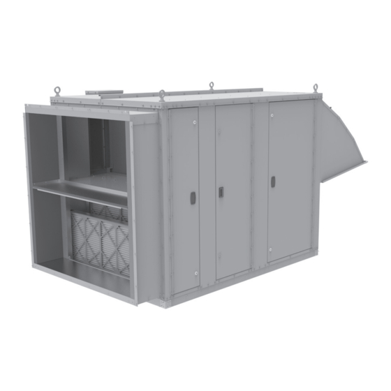
Energy Recovery Module, Model ERM
Prior to installation to the main ventilation unit, Model MPR.
WARNING
1. Improper installation, adjustment, alteration,
service or maintenance can cause property
damage, injury or death, and could cause
exposure to substances which have been
determined by various state agencies
to cause cancer, birth defects or other
reproductive harm. Read the installation,
operating and maintenance instructions
thoroughly before installing or servicing this
equipment.
2. The power supply wiring for the Energy
Recovery Module, model ERM, comes
from a single point power connection on
the main ventilation unit, model MPR.
Disconnect power supply at model MPR
before making wiring connections or servicing
this equipment. Follow all applicable safety
procedures to prevent accidental power up.
Failure to do so can result in injury or death
from electrical shock or moving parts and
may cause equipment damage.
3. When the dead front disconnect switch(es)
(for main unit model MPR and/or powered
convenience outlet option) is in the "OFF"
position, supply power remains energized
INSTALLATION AND SERVICE MANUAL
energy recovery module, model ERM
(refer to page 3 for use with APPLICABLE MODELS)
at the line (supply) side of the dead front
disconnect switch(es). The switch body is
located inside of another junction box to
protect against contact with the live wiring. The
junction box must not be disassembled unless
the main power supply from the building to the
unit is de-energized.
4. For units equipped for dual power supply
sources, both sources of power must be
disconnected to prevent electrical shock and
equipment damage.
As with any mechanical equipment, personal
injury can result from contact with sharp sheet
metal edges. Be careful when you handle this
equipment.
IMPORTANT
1. The use of this manual is specifically
intended for a qualified installation and
service agency. All installation and service of
this equipment must be performed by a
qualified installation and service agency.
2. These instructions must also be used in
conjunction with the Installation and Service
Manual originally shipped with the model
MPR unit, in addition to any other
accompanying component supplier literature.
Inspection on Arrival
Refer to page 3 for inspection instructions upon unit arrival.
THIS MANUAL IS THE PROPERTY OF THE OWNER.
PLEASE BE SURE TO LEAVE IT WITH THE OWNER
ATH15-520.2
ATH15-520.2
WARNING
CAUTION
WHEN YOU LEAVE THE JOB.
5H0816850001
July, 2021
1
Advertisement
Table of Contents

Related Manuals for Modine Manufacturing Atherion ERM


Summary of Contents for Modine Manufacturing Atherion ERM
- Page 1 ATH15-520.2 5H0816850001 July, 2021 INSTALLATION AND SERVICE MANUAL energy recovery module, model ERM (refer to page 3 for use with APPLICABLE MODELS) Energy Recovery Module, Model ERM WARNING at the line (supply) side of the dead front disconnect switch(es). The switch body is located inside of another junction box to protect against contact with the live wiring.
-
Page 2: Table Of Contents
SPECIAL PRECAUTIONS / TABLE OF CONTENTS SPECIAL PRECAUTIONS WARNING THE INSTALLATION AND MAINTENANCE INSTRUCTIONS IN THIS MANUAL MUST BE FOLLOWED TO PROVIDE SAFE, EFFICIENT AND TROUBLE-FREE OPERATION. IN Ensure that the supply voltage to the unit, as indicated ADDITION, PARTICULAR CARE MUST BE EXERCISED on the serial plate, is not 5% greater than the rated REGARDING THE SPECIAL PRECAUTIONS LISTED voltage. -
Page 3: Si (Metric) Conversion Factors
SI (METRIC) CONVERSION FACTORS / UNIT LOCATION SI (METRIC) CONVERSION FACTORS UNIT LOCATION DANGER Table 3.1 To Convert Multiply By To Obtain To Convert Multiply By To Obtain 1.699 m3/min “W.C. 0.24 Units must not be installed where they may be exposed to Btu/ft3 0.037 mJ/m3... -
Page 4: Roof Curb Installation/Duct/Utility Connections
ROOF CURB INSTALLATION / DUCT / UTILITY CONNECTIONS Duct Installation Roof Curb Installation The unit is designed to be close coupled to the MPR unit An optional roof curb is available to simplify site preparation through the factory installed transition duct. The inlet and and raise the unit above roof water and snow level for exhaust discharge openings are designed to be protected with drainage. -
Page 5: Rigging Instructions/Unit Installation
RIGGING INSTRUCTIONS / UNIT INSTALLATION Rigging Instructions Unit Installation Four 1.5" eye bolts at the top of the unit in each corner are Follow site preparation instructions for the roof curb before supplied to facilitate lifting the unit. For either crane or helicopter installation. -
Page 6: From Electrical Shock Or Moving Parts And May Cause
ELECTRICAL CONNECTIONS Electrical Connections WARNING Once both the MPR unit and ERM unit are mated, the pre- wired power and control wires in the MPR unit are to be routed through the inside of the duct transition and into the The power supply wiring for the Energy Recovery control compartment in the ERM unit (refer to Figure 9.1). -
Page 7: Start-Up Procedure
START-UP PROCEDURE General Turn on power to the unit at the disconnect switch at the WARNING MPR unit. Note: The unit includes a door switch installed inside the The power supply wiring for the Energy Recovery exhaust blower section access door. When the Module, model ERM, comes from a single point power door is opened, the switch interrupts power to a connection on the main ventilation unit, model MPR. - Page 8 START-UP PROCEDURE - CONTINUED Blower Adjustments Turn on power to the MPR unit and initiate blower motor operation. For guidance, refer to the Controls Manual that The units are designed for ease of airflow adjustments, within shipped with the MPR unit. certain limits, for field balancing against actual external static pressure conditions.
-
Page 9: Unit Features/Options Location Drawings
UNIT COMPONENT IDENTIFICATION / LOCATION Figure 9.1 - Energy Recovery Module Component Locations (S) MPR Unit to ERM Unit transition duct 13. (S) Outside air filters (S) Controls compartment with side wiring entrance 14. (O) Outside air filters pressure drop switch (S) Power distribution block 15. -
Page 10: Dimensions/Weights
DIMENSIONS - UNIT Figure 10.1 - Unit Dimensions 93.54 72.36 69.18 25.87 12.10 EXHAUST AIR GRAVITY DAMPER & OUTLET HOOD (4) 1.50" LIFTING EYE BOLTS (EACH CORNER OF UNIT) 60.14 65.92 ACCESSORY RAINHOOD AND BIRDSCREEN (FIELD INSTALLED ACCESSORY) 86.19 139.22 84.64 80.56 102.45... - Page 11 DIMENSIONS - UNIT BASE Figure 11.1 - Unit Base Dimensions 2.53 2.53 59.22 85.22 90.28 BASE ASSEMBLY AS VIEWED FROM BOTTOM 90.28 4.09 BASE ASSEMBLY AS VIEWED FROM SIDE LANDING AREA 2.53 1.37 FOR ROOF CURB INSIDE BASE ASSEMBLY DETAIL VIEW ATH15-520.2...
- Page 12 DIMENSIONS - ROOF CURBS Figure 12.1 - Roof Curb Dimensions 1.75 1.75 1.75 57.75 54.25 INSIDE 1.75 83.75 80.25 1.12 INSIDE 14.0 OR 24.0 SEE SCHEDULE Table 12.1 - Roof Curb Weight (approx) - lbs. Section Description Weight 14” - Uninsulated Roof Curb 24”...
-
Page 13: General Maintenance
GENERAL MAINTENANCE Outdoor Air Sensor WARNING Remove sensor from mounting bracket. Remove any dust or dirt that may be clogging the screen When the dead front disconnect switch(es) (for main unit material covering the air sample inlet openings on the end model MPR and/or powered convenience outlet option) is of the sensor probe. -
Page 14: Service & Troubleshooting
SERVICE & TROUBLESHOOTING WARNING CAUTION Do not reuse any mechanical or electrical component which When servicing or repairing this equipment, use only factory- has been wet. Such component must be replaced. approved service replacement parts. Refer to the rating plate on the unit for complete unit model number, serial number, IMPORTANT and company phone number before contacting the factory. -
Page 15: Serial Plate
SERIAL PLATE AND MODEL NOMENCLATURE Model Identification The unit is equipped with a serial plate located on the door of the controls cabinet as shown in Figure 15.1. When servicing, repairing or replacing parts on these units, locate the model Serial Plate of the unit and always give the complete Model Number and Serial Number of the unit. - Page 16 As Modine Manufacturing Company has a continuous product improvement program, it reserves the right to change design and specifications without notice. Modine Manufacturing Company 1500 DeKoven Avenue Racine, WI 53403 Phone: 1.800.828.4328 (HEAT) www.modinehvac.com © Modine Manufacturing Company 2021 ATH15-520.2...
Need help?
Do you have a question about the Atherion ERM and is the answer not in the manual?
Questions and answers