
Related Manuals for THORLABS MX10B Series


Summary of Contents for THORLABS MX10B Series
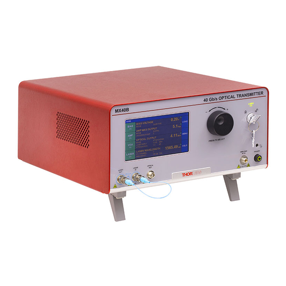
- Page 1 MX10B Series 12.5 Gb/s Optical Transmitters MX40B Series 40 Gb/s Optical Transmitters User Guide...
-
Page 3: Table Of Contents
4.8.2 System Information Page ........................24 4.8.3 Accent LED Settings Page ........................ 24 4.8.4 Thorlabs Help Page .......................... 25 Chapter 5 Specifications ................................. 26 General System Specifications ........................26 ... - Page 4 Replacement Parts ............................33 Replacing the Main Fuse ..........................34 Chapter 9 Troubleshooting ..............................35 Chapter 10 Declarations of Conformity ......................... 36 Chapter 11 Thorlabs Worldwide Contacts ........................38 ...
-
Page 5: Chapter 1 Introduction
RF amplifiers is user-adjustable. Variable optical attenuators (VOAs) and power monitors enable completely automatic control and stabilization of the optical output power. Transmitters in the MX10B series include an external loop-back cable for the driver RF output and modulator RF input ports, which provides the opportunity to use an external driver, if desired. -
Page 6: Block Diagram
The Laser In port uses PM fiber with light linearly polarized along the slow axis as shown on the front panel. Maximum input power is 20 dBm (100 mW). In the MX10B series of transmitters, the user also has the option of using their own modulator driver connected to the Modulator RF In port. -
Page 7: Front And Back Panel Overview
MX10B, MX40B Series of Optical Transmitters Chapter 1: Introduction 1.4 Front and Back Panel Overview Figure 2 Front Panel Callout Description MX10B Series MX40B Series Touchscreen Display Adjustment Knob Key Switch and Indicator Lasing Disabled; Lasing Enabled Grounding Jack (Banana... - Page 8 MX10B, MX40B Series of Optical Transmitters Chapter 1: Introduction Figure 3 Back Panel Callout Description MX10B Series MX40B Series I/O Port DB-15 DB-15 Option Label RS-232 Port DB-9 DB-9 USB Port, Type B Laser Interlock 2.5 mm 2.5 mm Power Connector...
-
Page 9: Chapter 2 Safety
If equipment is used in a manner not specified by the manufacturer, the protection provided by the equipment may be impaired. Only with written consent from Thorlabs may changes to single components be carried out or components not supplied by Thorlabs be used. -
Page 10: Precautions
3 meters (9.8 feet). Thorlabs is not responsible for any radio television interference caused by modifications of this equipment or the substitution or attachment of connecting cables and equipment other than those specified by Thorlabs. The correction of interference caused by such unauthorized modification, substitution or attachment will be the responsibility of the user. -
Page 11: Chapter 3 Quick Start Guide
PM Loopback Fiber Cable Installed Figure 7 Amplifier RF Out present only on the MX10B series of transmitters. This cable is not installed on the MX40B transmitter series. Insert the key into the interlock switch and turn it towards the unlock symbol ( ). -
Page 12: Controls On The Home Page
MX10B, MX40B Series of Optical Transmitters Chapter 3: Quick Start Guide 3.2 Controls on the Home Page The MX10B and MX40B series of transmitters can be fully controlled by using the resistive touchscreen display for all functions. The screen is sensitive to the touch of a finger or a plastic stylus, and selections are made by tapping the on-screen button of interest. -
Page 13: System Wavelength Setting
MX10B, MX40B Series of Optical Transmitters Chapter 3: Quick Start Guide System Wavelength Setting The operational wavelength range of the MX10B and MX40B series extends from 1250 nm to 1610 nm. The three calibration wavelengths of the power monitors, 1310 nm, 1550 nm, and 1590 nm, represent the centers of the O-band, C-band, and L-band and provide the user with accurate power readings at or near those wavelengths. -
Page 14: Controls On The Settings
MX10B, MX40B Series of Optical Transmitters Chapter 3: Quick Start Guide 3.4 Controls on the Settings Pages The Settings pages all follow the same general design and functionality as shown in the example screen shot below. The upper section with white letters displays the parameters that can be changed. Simply tap on the parameter of interest to highlight it, and the controls for that parameter will be presented. -
Page 15: Chapter 4 Operating Instructions
MX10B, MX40B Series of Optical Transmitters Chapter 4: Operating Instructions Chapter 4 Operating Instructions 4.1 The Modulator Transmission Function The Mach-Zehnder Modulator (MZM) has a repetitive transmission function with applied voltage as can be seen in the diagram below. In order for it to work correctly, a DC bias voltage must be applied and maintained at the desired set point. The high- frequency AC signal can then be applied to the modulator to enable the correct optical modulation of the laser beam. -
Page 16: Bias Settings Page
MX10B, MX40B Series of Optical Transmitters Chapter 4: Operating Instructions 4.3 Bias Settings Page To get to the Bias Settings page tap the Bias monitors pane on the Home page. The Bias page contains the settings for controlling the modulator bias and operating modes. There are four modes for MZM bias control: 1) Quadrature, 2) Peak, 3) Null, and 4) Manual. -
Page 17: Quadrature Mode
MX10B, MX40B Series of Optical Transmitters Chapter 4: Operating Instructions 4.3.1 Quadrature Mode Quadrature is the default mode and biases the MZM at the 50% point on the MZM transmission curve (see figure). This is the recommended mode for digital signals such as On-Off-Keying (OOK) that require a high extinction ratio. The screen-shot below shows the parameters that can be controlled in the Quadrature mode. - Page 18 MX10B, MX40B Series of Optical Transmitters Chapter 4: Operating Instructions The dither tone frequency may be changed by tapping the Dither Frequency field. Standard frequencies are available on the blue buttons, or a custom frequency may be chosen by pressing User Define. The dither tone frequency usually has very little effect on the accuracy of the bias control, but in some cases a different frequency may work better or be desirable depending on the RF signal applied, or the specific application.
-
Page 19: Peak Mode
MX10B, MX40B Series of Optical Transmitters Chapter 4: Operating Instructions 4.3.2 Peak Mode The Peak Mode adjusts the DC bias voltage so the transmission is centered at a nearby transmission maximum. In this mode only dither frequency and amplitude settings are available. These controls and settings are the same as previously described for the Quadrature mode. -
Page 20: Manual Mode
MX10B, MX40B Series of Optical Transmitters Chapter 4: Operating Instructions 4.3.4 Manual Mode The Manual mode allows the user to bias the modulator at any point of the transmission function desired. Manual mode offers two modes of operation: 1) Constant Bias, and 2) Constant Ratio. In both of these modes, the dither function is not active, and the controller uses different techniques to hold the bias steady. - Page 21 MX10B, MX40B Series of Optical Transmitters Chapter 4: Operating Instructions In the Constant Ratio mode there is an option to select between the two available operating regions by selecting the Slope field. Positive slope is the non-inverting operating point where increasing voltage on the MZM results in increasing optical output power.
-
Page 22: Amplifier Settings Page
MX10B, MX40B Series of Optical Transmitters Chapter 4: Operating Instructions 4.4 Amplifier Settings Page To get to the Amplifier Settings page, tap on the Amplifier monitor pane on the Home page. The Amplifier has a fixed gain that it applies to a user input signal. The signal is then routed to the RF input port of the MZM via the front panel loop-back cable. There are two Modes for the amplifier: 1) Digital and 2) Analog, but both work with the same fixed gain. - Page 23 MX10B, MX40B Series of Optical Transmitters Chapter 4: Operating Instructions The Crossing Point field allows the user to adjust the eye crossing point in the eye diagram as depicted in the diagram below. It provides an adjustment to optimize the bit-error-rate (BER) performance of a transmission link by adjusting the amplifier’s internal threshold levels.
-
Page 24: Variable Optical Attenuator Settings Page
MX10B, MX40B Series of Optical Transmitters Chapter 4: Operating Instructions 4.5 Variable Optical Attenuator Settings Page To get to the Variable Optical Attenuator (VOA) Settings page, tap in the VOA monitors pane on the Home page. The VOA provides the means for adjusting and stabilizing the output power after the MZM. Note that the power measurement units for the entire interface are set on this page. -
Page 25: Laser Settings Page
MX10B, MX40B Series of Optical Transmitters Chapter 4: Operating Instructions Laser Settings Page To access the Laser Settings page, tap on the Laser monitors pane on the Home page. Here the user can control the laser wavelength and choose whether or not to use the dither feature to stabilize the wavelength (available for models with C- or L-band lasers only). -
Page 26: Load Page
MX10B, MX40B Series of Optical Transmitters Chapter 4: Operating Instructions FM Noise Spectrum with and without dither. Wavelength stability is improved with dither, but at the expense of adding noise (blue line). Red line shows Low Noise operation with dither turned off. Figure 39 FM Noise Spectrum of the Laser 4.7 Load Page... -
Page 27: Menu Page
Tap here to control the accent LEDs producing the light emanating from the bottom of the instrument. Tap here to find help from Thorlabs Technical Support. Figure 42 Controls on the Menu Page 4.8.1 Display and Sound Settings Page To open the screen shown below, tap the DISPLAY AND SOUNDS button on the Menu pane. -
Page 28: System Information Page
MX10B, MX40B Series of Optical Transmitters Chapter 4: Operating Instructions 4.8.2 System Information Page To open the screen shown below, tap the SYSTEM INFORMATION button on the Menu pane. The System Information page displays the installed hardware and software versions. This is useful information when in the need for tech-support or to verify firmware revisions. -
Page 29: Thorlabs Help Page
To open the screen shown below, tap the THORLABS HELP button on the Menu pane. The Thorlabs Help page displays the Tech Support phone number, Thorlabs web site, and the installed hardware and software versions. This information will be useful when speaking with Tech Support. -
Page 30: Chapter 5 Specifications
Quoted only for the MX10B series. The external loop-back between output of the RF amplifier and the internal modulator is accessible to the operator in the MX10B series of transmitters, but the connection is made directly inside the housing of the MX40B series. -
Page 31: Power And Environmental Specifications
Monitor VOA Insertion Loss 0.4 dB Typical VOA Response Time 5.4 Internal Amplifier Specifications Parameter Typical Values Notes MX10B Series 35 ps Large Signal, Digital Response Rise/Fall Time MX40B Series 8 ps MX10B Series 34 dB RF Amplifier Gain... -
Page 32: Laser Specifications
MX10B, MX40B Series of Optical Transmitters Chapter 5: Specifications 5.6 Laser Specifications Parameter Unit Typ. C-Band Tunable Laser (MX10B, MX40B) Optical Output Power 12.5 13.5 14.5 Frequency Range 191.50 196.25 Wavelength Range 1527.6 1565.5 -1.5 Frequency Accuracy Tuning Resolution Tuning Speed (Between Wavelengths) Side Mode Suppression Ratio (SMSR) Optical Signal to Noise Ratio (OSNR) Intrinsic Linewidth... -
Page 33: Chapter 6 Control And Pc Connections
Item # into the search field. The instrument’s firmware can be updated by uploading the new version from a PC via the USB port. Thorlabs’ technical support can provide up-to-date information on available firmware revisions and control functions. -
Page 34: The Laser Safety Interlock
If the switch returns to a closed condition the laser source must be turned on again in the touchscreen GUI. All units shipped from Thorlabs are configured with a shorting device installed in the Interlock connector. If you are not going to use this feature, then leave the shorting device installed. -
Page 35: Chapter 7 Mechanical Drawings
Chapter 7: Mechanical Drawings Chapter 7 Mechanical Drawings 7.1 MX10B Series 122.0 mm 134.8 mm (4.80") (5.31") 250.0 mm (9.84") 300.0 mm (11.81") 322.2 mm (12.69") Figure 50 Mechanical Drawing of the MX10B Series Rev. D, March 19, 2019 Page 31... -
Page 36: Mx40B Series
MX10B, MX40B Series of Optical Transmitters Chapter 7: Mechanical Drawings 7.2 MX40B Series 122.0 mm 134.8 mm (4.80") (5.31") 250.0 mm (9.84") 300.0 mm (11.81") 322.2 mm (12.69") Figure 51 Mechanical Drawing of the MX40B Series Page 32 TTN048897-D02... -
Page 37: Chapter 8 Maintenance, Repair, And Fuses
Fiber End-Face Cleaner for Patch Cords The optical connectors on the front panel may be cleaned using a 2.5 mm bulkhead cleaner such as the Thorlabs FBC1. This allows the user to clean the fiber end-face without removing it from the internal bulkhead adapter. -
Page 38: Replacing The Main Fuse
Investigate the fuse. This can be done with a simple continuity check. If in doubt, replace the fuse. A spare fuse is stored in the fuse holder. Additional replacement fuses can be purchased from Thorlabs. Always use fuses of the same type as the original. -
Page 39: Chapter 9 Troubleshooting
Below is some information about status indicators and a few checks to help in troubleshooting general problems. If you have any questions, please contact your local Thorlabs Technical Support office. If the unit does not appear to turn on correctly, please check the following items: ... -
Page 40: Chapter 10 Declarations Of Conformity
MX10B, MX40B Series of Optical Transmitters Chapter 10: Declarations of Conformity Chapter 10 Declarations of Conformity Page 36 TTN048897-D02... - Page 41 MX10B, MX40B Series of Optical Transmitters Chapter 10: Declarations of Conformity Rev. D, March 19, 2019 Page 37...
-
Page 42: Chapter 11 Thorlabs Worldwide Contacts
(see right), were sold to and are currently owned by a company or institute within the EC, and are not dissembled or contaminated. Contact Thorlabs for more information. Waste treatment is your own responsibility. “End of life” units must be returned to Thorlabs or handed to a company specializing in Annex I waste recovery. - Page 44 www.thorlabs.com...
Need help?
Do you have a question about the MX10B Series and is the answer not in the manual?
Questions and answers