Table of Contents
Advertisement
Quick Links
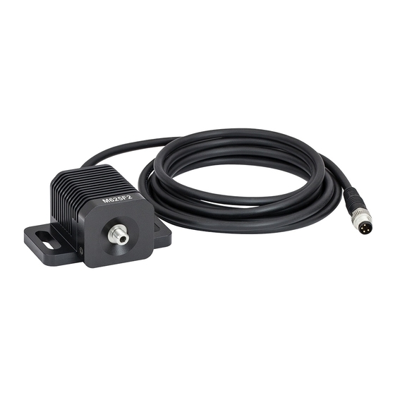
Description
Thorlabs' M625F2 Fiber-Coupled LED has a nominal wavelength of 625 nm, outputs more than 13.2 mW of
power, and is mounted to the end of a heat sink. The output is compatible with SMA fiber connectors. This LED
needs to be supplied with a constant current that must not exceed 1000 mA.
Specifications
Specification
Color
Nominal Wavelength
Test Current for Typical LED Power
Maximum Current (CW)
Bandwidth (FWHM)
Electrical Power
Typical Lifetime
Operating Temperature
(Non-Condensing)
Storage Temperature
Emitter Size
a
Risk Group
a.
According to the standard IEC 62471:2006, Photobiological Safety of Lamps and Lamp Systems
a
Dominant Wavelength
LED Power Output (Ø400 µm Fiber)
LED Power Output (Ø200 µm Fiber)
Forward Voltage
a
When Driven with the Test Current
a.
For multimode fiber with a Ø400 µm core and 0.39 NA (Item # FT400EMT).
b.
For multimode fiber with a Ø200 µm core and 0.22 NA (Item # FG200UCC).
c.
Operating Instructions
Be sure to provide air ventilation in order to avoid overheating, drops in optical power, and reduced lifetime. Each LED
has a characteristic switch-on behavior, which depends on the LED properties and environment conditions. An important
criterion is the heat dissipation. The M625F2 has a unique thermal and heat sink design that reduces the power decay to
a minimum.
M625F2's male connector is a standard M8 x 1 sensor circular connector. Pins 1 and 2 connect to the LED. Pins 3
and 4 are used for the internal EEPROM. Only use these connections when using a Thorlabs LED driver.
After an LED is switched on, it will warm up which can cause a decay in optical power. The heat sink of the M625F2
provides good thermal management, reducing the loss of power as the LED reaches its equilibrium temperature.
M625F2
M625F2
Symbol
λ
p
a,b
P
out
a,c
P
out
V
F
Fiber-Coupled LED
625 nm
Value
Red
625 nm
1000 mA
1000 mA
15 nm
2200 mW
>50 000 h
0 to 40 °C
-40 to 70 °C
1 mm x 1 mm
RG0 – Exempt Risk Group
Min
Typical
620 nm
625 nm
13.2 mW
17.5 mW
-
5.7 mW
-
2.2 V
February 1, 2018
MTN005534‐S01, Rev B
Max
630 nm
-
-
-
Advertisement
Table of Contents

Related Manuals for THORLABS M625F2


Summary of Contents for THORLABS M625F2
- Page 1 4 are used for the internal EEPROM. Only use these connections when using a Thorlabs LED driver. After an LED is switched on, it will warm up which can cause a decay in optical power. The heat sink of the M625F2 provides good thermal management, reducing the loss of power as the LED reaches its equilibrium temperature.
- Page 2 Fiber connection to the M625F2 must be made via an SMA fiber connector. We recommend using multimode (MMF) fiber with the M625F2. Optical output power is specified for a Ø400 µm MMF with an NA of 0.39 at the maximum allowed LED current. Optical power increases proportionally with the core diameter and nearly proportionally to the square of the NA.
- Page 3 The M625F2 is not water resistant and must be protected from adverse weather conditions. To avoid damage, do not expose it to spray, liquids, or solvents. The M625F2 does not contain any parts serviceable by the user and does not require regular user maintenance. Do not open the enclosure. If a malfunction occurs, contact Thorlabs for return instructions.
Need help?
Do you have a question about the M625F2 and is the answer not in the manual?
Questions and answers