Advertisement
Available languages
Available languages
Quick Links
H-6312
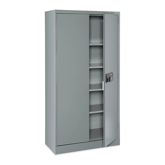
ELECTRONIC STORAGE
CABINET
PAGE 1 OF 15
1-800-295-5510
uline.com
TOOLS NEEDED
Para Español, vea páginas 6-10.
Pour le français, consulter les pages 11-15.
11/32" Nut Driver
(included)
Flathead Screwdriver
Hammer
CAUTION! Some parts may have sharp
edges. Take care when handling various
pieces to avoid injury. For safety,
wear work gloves when assembling.
0321 IH-6312
Advertisement

Related Manuals for U-Line H-6312


Summary of Contents for U-Line H-6312
- Page 1 Para Español, vea páginas 6-10. Pour le français, consulter les pages 11-15. H-6312 1-800-295-5510 uline.com ELECTRONIC STORAGE CABINET TOOLS NEEDED 11/32" Nut Driver (included) Flathead Screwdriver Hammer CAUTION! Some parts may have sharp edges. Take care when handling various pieces to avoid injury. For safety, wear work gloves when assembling.
- Page 2 PARTS ASSEMBLY DESCRIPTION QTY. Back Right Side Panel Left Side Panel Shelf Sill Bottom Left Door Right Door Hinge Pin #8-32 x 3/8" Bolt (Not Shown) #8-32 Nut (Not Shown) PAGE 2 OF 15 0321 IH-6312...
- Page 3 ASSEMBLY NOTE: Before assembly, to avoid being locked 4. Attach the right side (3) to the back as in step 2. out of cabinet, remove the key for manual Make sure the flange is around the back and that entry from the battery compartment on the the lances on the shelf adjustment strips are pointed back of the electronic lock.
- Page 4 ASSEMBLY CONTINUED Set the unit upright and tighten all nuts and bolts 10. Attach the right door (9) to the unit the same way the around the entire unit. left door was attached. (See Figure 9) 8. Insert the shelves (4) at desired levels. (See Figure 7) NOTE: If having issues with doors aligning, it may be due to cabinet not sitting level.
-
Page 5: Changing Security Code
ELECTRONIC LOCK INSTRUCTIONS CONTINUED GETTING STARTED KEY ENTRY 1. The battery compartment is located on the back of 1. The key slot is located underneath the cover, next to the electronic lock. To insert batteries, lift up on the the handle. Remove cover by prying off from bottom. compression tab at the bottom of the compartment. - Page 6 H-6312 800-295-5510 uline.mx GABINETE ELECTRÓNICO PARA ALMACENAMIENTO HERRAMIENTAS NECESARIAS Desarmador de Tuercas de 11/32" (Incluido) Desarmador Plano Martillo ¡PRECAUCIÓN! Algunas partes podrían tener bordes filosos. Tome precauciones al manejar varias piezas para evitar lesiones. Por seguridad, cuando lo ensamble use guantes de trabajo.
- Page 7 PARTES ENSAMBLE DESCRIPCIÓN CANT. Panel Posterior Panel Izquierdo Panel Derecho Repisa Placa Frontal Panel de Fondo Panel Superior Puerta Izquierda Puerta Derecha Pasador de la Bisagra Perno #8-32 x 3/8" (No se Muestra) Tuerca #8-32 (No se Muestra) PAGE 7 OF 15 0321 IH-6312...
- Page 8 ENSAMBLE NOTA: Antes de ensamblarlo, para evitar que Una el panel derecho (3) al posterior igual que en el paso se cierre el gabinete, saque la llave para abrir 2. Asegúrese de que la pestaña quede por debajo y de manualmente del compartimento de las baterías, que todas las lancetas en las tiras de ajuste para repisas localizado en la parte de atrás de la cerradura...
- Page 9 CONTINUACIÓN DE ENSAMBLE Ponga la unidad de pie y apriete todas las tuercas y 10. Instale la puerta derecha (9) a la unidad de la misma pernos de la unidad. manera en que colocó la puerta izquierda. (Vea Diagrama 9) 8.
- Page 10 CONTINUACIÓN INSTRUCCIONES DE LA CERRADURA ELECTRÓNICA INICIO ACCESO DE LA LLAVE El compartimento para las baterías se encuentra La entrada de la llave se encuentra debajo de la en la parte de atrás de la cerradura. Para colocar cubierta, junto al asa. Retire la cubierta zafándola las baterías, levante la placa de compresión en la de la parte de abajo.
- Page 11 H-6312 1-800-295-5510 uline.ca ARMOIRE D'ENTREPOSAGE ÉLECTRONIQUE OUTILS REQUIS Tournevis à douille de 11/32 po (inclus) Tournevis à tête plate Marteau MISE EN GARDE! Certaines pièces peuvent avoir des bords tranchants. Faites attention lorsque vous manipulez les diverses pièces afin d'éviter les blessures.
- Page 12 PIÈCES MONTAGE DESCRIPTION QTÉ Panneau arrière Panneau latéral gauche Panneau latéral droit Tablette Seuil de cadre Panneau inférieur Panneau supérieur Porte gauche Porte droite Axe de charnière Boulon nº 8-32 x 3/8 po (non illustré) Écrou nº 8-32 (non illustré) PAGE 12 OF 15 0321 IH-6312...
-
Page 13: Montage
MONTAGE REMARQUE : Pour éviter de bloquer l'accès 4. Fixez le panneau latéral droit (3) au panneau arrière de la même manière qu'à l'étape 2. Assurez-vous à l'armoire, enlevez la clé pour l'ouverture que la bride repose par-dessus le panneau arrière manuelle du compartiment de la pile à... - Page 14 MONTAGE SUITE Placez l'unité en position verticale et serrez tous les 10. Fixez la porte droite (9) à l'unité de la même manière écrous et boulons sur l'ensemble de l'unité. que pour la porte gauche. (Voir Figure 9) 8. Insérez les tablettes (4) à la hauteur souhaitée. REMARQUE : Pour faciliter l'installation de la (Voir Figure 7) tablette, une personne, à...
-
Page 15: Avant De Commencer
INSTRUCTIONS DE LA SERRURE ÉLECTRONIQUE SUITE AVANT DE COMMENCER OUVERTURE AVEC LA CLÉ Le compartiment à pile est situé sur l'arrière de la La fente pour la clé est située au-dessous de serrure électronique. Pour insérer les piles, soulevez la protection, à côté de la poignée. Retirez la l'onglet de compression se trouvant au fond du protection en tirant par le bas.
Need help?
Do you have a question about the H-6312 and is the answer not in the manual?
Questions and answers