
Related Manuals for FS S58 Series


Summary of Contents for FS S58 Series
- Page 1 S58 Series 10G/25G Switches HYPER CONVERGED INFRASTRUCTURE SWITCHES Quick Start Guide V2.0...
- Page 2 Introduction Thank you for choosing S58 series switches. This guide is designed to familiarize you with the layout of the switches and describes how to deploy the switches in your network. 10/100/1000 BA SE -T 1 0 / 2 5 G...
-
Page 3: Hardware Overview
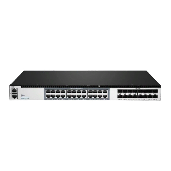
Hardware Overview Front Panel Ports S5850-24T16B 1 0 / 1 0 0 / 1 0 0 0 B A S E -T 1 0 / 2 5 G S 5 8 5 0 - 2 4 T 1 6 B 20 21 28 29 34 35... - Page 4 S5800-8TF12S RJ45 10G SFP+ PWR1 PWR2 STCK 14 15 18 19 S 5 8 5 0 - 8 T F 1 2 S 10/100/1000 BASE-T 100/1000 BASE-X 10G BASE-X Ports Description RJ45 10/100/1000 BASE-T ports for Ethernet connection Combo Ports SFP ports for 100/1000 BASE-X transceivers SFP+ SFP+ ports for 1/10G transceivers...
- Page 5 LEDs Status Description Green System is abnormal. Blinking Green Quickly The system is running in u-boot mode. (2Hz) Blinking Green Slowly The system is normally running. (0.5Hz) Amber The system occurs alarm or error. Blinking Amber Quickly System is initial in u-boot mode. Blinking Amber Slowly System software is in initial state.
-
Page 6: Installation Requirements
Back Panels S5850-24T16B/S5850-24T16S 100-240Vac 100-240Vac 50-60HZ 3-1.5A 50-60HZ 3-1.5A FAN4 FAN1 Grounding Point 4 Hot-swappable Fans 2 Hot-swappable Power Supplies S5800-8TF12S 100-240Vac 100-240Vac 50-60HZ 3-1.5A 50-60HZ 3-1.5A Grounding Points 4 Fans 2 Hot-swappable Power Supplies Installation Requirements Before you begin the installation, make sure that you have the following: Phillips screwdriver. -
Page 7: Mounting The Switch
Mounting the switch Desk Mounting 10 11 12 13 14 15 18 19 20 21 22 23 26 27 28 29 30 31 34 35 36 37 38 39 1. Attach four rubber pads to the bottom. 2. Place the chassis on the desk. Rack Mounting 1. -
Page 8: Grounding The Switch
2. Attach the switch to the rack using four M6 screws and cage nuts. Grounding the Switch 1. Connect one end of the grounding cable to a proper earth ground, such as the rack in which the switch is mounted. 2. -
Page 9: Connecting The Power
Connecting the Power 1. Plug the AC power cord into the power port on the back of the switch. 2. Connect the other end of the power cord to an AC power source. WARNING: Do not install power cable while the power is on. Connecting the RJ45 Ports 1. -
Page 10: Connecting The Console Port
Connecting the SFP+ Ports 1. Plug the compatible SFP+/ SFP transceiver into the SFP+ port. 2. Connect a ber optic cable to the ber transceiver. Then connect the other end of the cable to another ber device. Connecting the Console Port 1. - Page 11 Connecting the ETH Port 1. Connect one end of a standard RJ45 Ethernet cable to a computer. 2. Connect the other end of the cable to the ETH port on the front of the switch. Con guring the Switch Con guring the Switch Using the Web-based Interface Step 1: Connect the computer to the Management port of the switch using the network cable.
- Page 12 Step 3: Open a browser, type http://192.168.1.1, and enter the default username and password, admin/admin. Step 4: Click Sign in to display the web-based con guration page. Con guring the Switch Using the Console Port Step 1: Connect a computer to the switch's console port using the supplied console cable. Step 2: Start the terminal simulation software such as HyperTerminal on the computer.
-
Page 13: Troubleshooting
5. If you still cannot access the con guration page, please restore the switch to its factory defaults. Then the IP address of your PC should be set as 192.168.1.x ("x" is any number from 2 to 254) and Subnet Mask as 255.255.255.0. Support and Other Resources Download https://www.fs.com/download.html Help Center https://www.fs.com/service/help_center.html https://www.fs.com/contact_us.html Contact Us... -
Page 14: Product Warranty
Product Warranty FS ensures our customers that any damage or faulty items due to our workmanship, we will o er a free return within 30 Days from the day you receive your goods. This excludes any custom made items or tailored solutions. - Page 15 Q.C. PASSED Copyright © 2020 FS.COM All Rights Reserved.
Need help?
Do you have a question about the S58 Series and is the answer not in the manual?
Questions and answers