Table of Contents
Advertisement
Quick Links
Advertisement
Table of Contents

Subscribe to Our Youtube Channel
Related Manuals for NXP Semiconductors SAFE ASSURE FRDMGD31RPEVM


Summary of Contents for NXP Semiconductors SAFE ASSURE FRDMGD31RPEVM
-
Page 1: Frdmgd31Rpevm
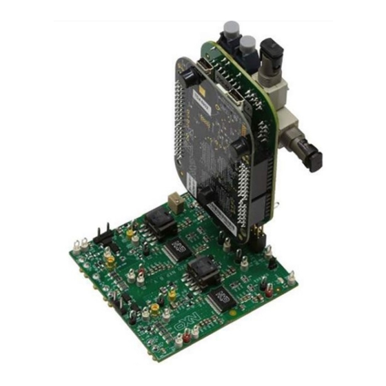
UM11401 FRDMGD31RPEVM half-bridge evaluation board Rev. 2 — 22 January 2021 User guide FRDMGD31RPEVM Figure 1. FRDMGD31RPEVM Your Global Source for RF, Wireless, IoT & Power Technologies www.richardsonrfpd.com | 800.737.6937 | 630.262.6800 4/2022... -
Page 2: Important Notice
UM11401 NXP Semiconductors FRDMGD31RPEVM half-bridge evaluation board Important notice NXP provides the enclosed product(s) under the following conditions: This evaluation kit is intended for use of ENGINEERING DEVELOPMENT OR EVALUATION PURPOSES ONLY. It is provided as a sample IC pre-soldered to a printed circuit board to make it easier to access inputs, outputs, and supply terminals. -
Page 3: Getting Started
UM11401 NXP Semiconductors FRDMGD31RPEVM half-bridge evaluation board Getting started The NXP analog product development boards provide an easy-to-use platform for evaluating NXP products. The boards support a range of analog, mixed-signal, and power solutions. They incorporate monolithic integrated circuits and system-in-package devices that use proven high-volume technology. -
Page 4: Required Equipment
UM11401 NXP Semiconductors FRDMGD31RPEVM half-bridge evaluation board 3.2 Required equipment To use this kit, you need: • Compatible SiC RoadPak module • DC link capacitor compatible with the SiC RoadPak module • 1.27 mm jumpers for configuration (included with kit) •... -
Page 5: Device Features
UM11401 NXP Semiconductors FRDMGD31RPEVM half-bridge evaluation board 4.3 Device features Table 1. Device features Device Description Features GD3100 The GD3100 is an • Compatible with current sense and temp sense advanced single IGBTs channel gate driver for • DESAT detection capability for detecting V IGBTs. -
Page 6: Low-Voltage Logic And Control Connector
UM11401 NXP Semiconductors FRDMGD31RPEVM half-bridge evaluation board Figure 2. Connecting FRDM-KL25Z, GD31xx half-bridge EVB and translator board 4.4.1 Low-voltage logic and control connector Low-voltage domain is 12 V VSUP domain that interfaces with the MCU and GD3100 control registers through the 24-pin connector interface. - Page 7 UM11401 NXP Semiconductors FRDMGD31RPEVM half-bridge evaluation board Figure 3. Evaluation board voltage and interface domains Table 2. Low-voltage domain 24-pin connector definitions Name Function AOUTL analog output duty cycle encoded signal (low side) for reading temperature via TSENSEA or voltage via AMUXIN n.c.
-
Page 8: Test Point Definitions
UM11401 NXP Semiconductors FRDMGD31RPEVM half-bridge evaluation board Table 2. Low-voltage domain 24-pin connector definitions ...continued Name Function n.c. not connected MOSIH master out slave in (high side) n.c. not connected CSBH chip select bar (high side) LED_PWR USB 3.3 V power for INTB LEDs (high side and low side) - Page 9 UM11401 NXP Semiconductors FRDMGD31RPEVM half-bridge evaluation board Table 3. Test point definitions Test point Definition Low-voltage domain VSUP DC voltage source connection point for VSUP power input of GD3100 devices. Typically supplied by vehicle battery +12 V DC. GND1 grounding points for low-voltage domain...
-
Page 10: Power Supply And Jumper Configuration
UM11401 NXP Semiconductors FRDMGD31RPEVM half-bridge evaluation board 4.4.3 Power supply and jumper configuration Figure 5. Power supply and jumper configuration Table 4. Jumper definitions Jumper Position Function PWMHSEL (J10) dead time fault protection enabled (high side) dead time fault protection disabled (use for short-circuit testing) -
Page 11: Bottom View
UM11401 NXP Semiconductors FRDMGD31RPEVM half-bridge evaluation board 4.4.4 Bottom view Figure 6. Evaluation board bottom view 4.4.5 Gate drive resistors • RGH - gate high resistor in series with the GH pin at the output of the GD3100 gate high driver and RoadPak module gate that controls the turn-on current for SiC MOSFET gate. -
Page 12: Led Interrupt Indicators
UM11401 NXP Semiconductors FRDMGD31RPEVM half-bridge evaluation board Figure 7. Gate drive resistors 4.4.6 LED interrupt indicators Figure 8. LED interrupt indicators UM11401 All information provided in this document is subject to legal disclaimers. © NXP B.V. 2021. All rights reserved. User guide Rev. -
Page 13: Kinetis Kl25Z Freedom Board
UM11401 NXP Semiconductors FRDMGD31RPEVM half-bridge evaluation board Table 5. LED interrupt indicators Description Low-side INTB connected to the INTB output pin of low-side driver indicating reported fault status when on (active LOW) High-side INTB connected to the INTB interrupt output pin of high-side driver indicating reported fault status when on (active LOW) 4.5 Kinetis KL25Z Freedom board... -
Page 14: To 5.0 V Translator Board
UM11401 NXP Semiconductors FRDMGD31RPEVM half-bridge evaluation board 4.6 3.3 V to 5.0 V translator board KITGD3160TREVB translator enables level shifting of signals from MCU 3.3 V to 5.0 V SPI communication. Figure 10. Translator board Table 6. Translator board jumper definitions Jumper... -
Page 15: Installation And Use Of Software Tools
UM11401 NXP Semiconductors FRDMGD31RPEVM half-bridge evaluation board Suggested equipment needed for test: • Rogowski coil high-current probe • High-voltage differential voltage probe • High sample rate digital oscilloscope with probes • DC link capacitor (power ring 700D407 425 μF, 900 V DC) •... -
Page 16: Installing Flexgui On Your Computer
UM11401 NXP Semiconductors FRDMGD31RPEVM half-bridge evaluation board 6.1 Installing FlexGUI on your computer The latest version of FlexGUI supports the GD3100 and GD3160. It is designed to run on any Windows 10 or Windows 8 based operating system. To install the software, do the following: 1. -
Page 17: Using The Flexgui
UM11401 NXP Semiconductors FRDMGD31RPEVM half-bridge evaluation board 5. Reboot the board by unplugging and replugging the connection to the OpenSDA port. Verify now that the device appears as a KL25Z device to continue. 6. Locate the most recent KL25Z firmware; which is distributed as part of the FlexGUI package. - Page 18 UM11401 NXP Semiconductors FRDMGD31RPEVM half-bridge evaluation board Figure 13. Kit selection FlexGUI settings • Access settings by selecting Settings from the File menu Figure 14. GUI settings menu UM11401 All information provided in this document is subject to legal disclaimers. © NXP B.V. 2021. All rights reserved.
- Page 19 UM11401 NXP Semiconductors FRDMGD31RPEVM half-bridge evaluation board • The Loader and Logs settings are shown below: Figure 15. Loader settings Figure 16. Logs settings UM11401 All information provided in this document is subject to legal disclaimers. © NXP B.V. 2021. All rights reserved.
- Page 20 UM11401 NXP Semiconductors FRDMGD31RPEVM half-bridge evaluation board • Access settings by selecting Settings from the File menu. • The Register Map and Tabs settings are shown below: Figure 17. Register map settings Figure 18. Tabs settings UM11401 All information provided in this document is subject to legal disclaimers.
- Page 21 UM11401 NXP Semiconductors FRDMGD31RPEVM half-bridge evaluation board Command Log window • The Command Log area informs the user about application events. Figure 19. Command Log area Global workspace controls • Always visible in the lower left corner of the main application window.
- Page 22 UM11401 NXP Semiconductors FRDMGD31RPEVM half-bridge evaluation board • Pins tab functionality – Set control levels. Default values are shown. – Read and automatically poll INTB pins (INTA pins are added for GD3160). – Control pins set values to a default to a functional state.
- Page 23 UM11401 NXP Semiconductors FRDMGD31RPEVM half-bridge evaluation board • Analog tab functionality – Read and poll ADC values from the high-voltage domain – Displays raw ADC and converted values Figure 23. Analog tab functionality Register map • Registers are grouped according to function; independent lines to read and write the registers •...
- Page 24 UM11401 NXP Semiconductors FRDMGD31RPEVM half-bridge evaluation board Gate Drive tab • Allows setting of parameters related to the gate drive; controls are disabled when not in config mode • Provides a more intuitive visual way to set parameters • All settings are automatically synchronized with the register controls.
- Page 25 UM11401 NXP Semiconductors FRDMGD31RPEVM half-bridge evaluation board Figure 26. Current sense tab DESAT & Seg Drive tab • Allows setting of parameters related to desat and segmented drive • Provides a more intuitive visual way to set parameters • All settings are automatically synchronized with the register controls.
- Page 26 UM11401 NXP Semiconductors FRDMGD31RPEVM half-bridge evaluation board Overtemperature tab • Allows setting of parameters related to overtemperature and overtemperature warning thresholds • Provides a more intuitive visual way to set parameters • All settings are automatically synchronized with the register controls.
- Page 27 UM11401 NXP Semiconductors FRDMGD31RPEVM half-bridge evaluation board Measurements tab • Allows monitoring and graphing of ADC and temperature values Figure 30. Measurements tab Status tab • Allows monitoring of Status 1, Status 2, and Status 3 register values • Status 1 and Status 2 faults can be cleared •...
-
Page 28: Troubleshooting
UM11401 NXP Semiconductors FRDMGD31RPEVM half-bridge evaluation board Figure 31. Status tab Pulse tab • Used for double pulse, short circuit, and PWM testing • Select desired T1, T2, and T3 timings for each test type; select enable then generate pulses Figure 32. Pulse tab 6.4 Troubleshooting... - Page 29 UM11401 NXP Semiconductors FRDMGD31RPEVM half-bridge evaluation board Problem Evaluation Explanation Corrective action(s) No PWM output (no fault reported) Check PWM jumper position on Incorrect PWM jumpers obstruct Set PWMH_SEL (J4) and translator board signal path but not report fault PWML_SEL (J5) jumpers properly, for desired control method: •...
-
Page 30: Schematics, Board Layout, And Bill Of Materials
UM11401 NXP Semiconductors FRDMGD31RPEVM half-bridge evaluation board Problem Evaluation Explanation Corrective action(s) SPIERR reported after SPI message Check bit length of message sent There is SPIERR if SCLK does not Use 24-bit message length for SPI see a n*24 multiple of cycles... -
Page 31: Revision History
UM11401 NXP Semiconductors FRDMGD31RPEVM half-bridge evaluation board Revision history Revision history Revision Date Description 20210122 Section 6.2 list item 6a: changed FlexGUI version 20200803 initial version UM11401 All information provided in this document is subject to legal disclaimers. © NXP B.V. 2021. All rights reserved. -
Page 32: Legal Information
NXP Semiconductors and its suppliers accept no liability for 10.1 Definitions inclusion and/or use of NXP Semiconductors products in such equipment or applications and therefore such inclusion and/or use is at the customer's own risk. - Page 33 UM11401 NXP Semiconductors FRDMGD31RPEVM half-bridge evaluation board Tables Tab. 1. Device features ..........5 Tab. 4. Jumper definitions ........... 10 Tab. 2. Low-voltage domain 24-pin connector Tab. 5. LED interrupt indicators ........13 definitions ............7 Tab. 6. Translator board jumper definitions ....14 Tab.
-
Page 34: Table Of Contents
UM11401 NXP Semiconductors FRDMGD31RPEVM half-bridge evaluation board Contents FRDMGD31RPEVM ..........1 Important notice ..........2 Getting started ............ 3 Kit contents/packing list ........3 Required equipment .......... 4 System requirements .........4 Getting to know the hardware ......4 Overview ............4 Board features ...........
Need help?
Do you have a question about the SAFE ASSURE FRDMGD31RPEVM and is the answer not in the manual?
Questions and answers