
Related Manuals for TapFlo Sanitary Series


Summary of Contents for TapFlo Sanitary Series
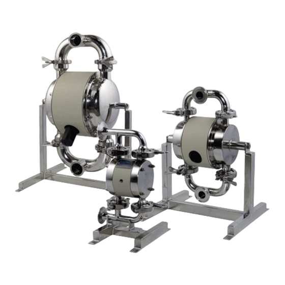
- Page 1 Sanitary Series Diaphragm Pumps edition 2018 rev 1 Original Instruction Read this instruction manual carefully, before you install and operate the pump Pump models: T/TX30 T/TX80 T/TX125 T/TX225 T/TX425 T/TX825...
-
Page 2: Table Of Contents
Optimization of the pump lifetime ................15 2.3. Pump stopping ......................... 16 2.4. Cleaning of the pump ......................16 2.4.1. CIP – Cleaning In Place ....................16 2.4.1.1. Drainage of the pump (T80 – T825) ................17 Tapflo sanitary pump series... - Page 3 5.9. T825 – Spare parts drawing ....................38 5.10. T825 – Spare parts list ......................38 5.11. T825 – Spare parts options ....................39 5.12. Stocking recommendation ....................40 5.13. How to order parts ....................... 40 Tapflo sanitary pump series...
- Page 4 Dimensions ..........................43 6.4. Technical data .......................... 45 6.5. Tightening torques ........................45 6.6. Permitted loads on manifolds ....................46 WARRANTY ..........................47 7.1. Warranty form .......................... 47 7.2. Returning parts ........................48 7.3. Warranty ........................... 48 Tapflo sanitary pump series...
- Page 5 Directive 2006/42/EC of European Parliament and of the Council of 17 May 2006 on machinery, amending Directive 95/16/EC; Mr Michał Śmigiel is authorized to compile the technical file. Tapflo Sp. z o.o. ul. Czatkowska 4b 83-110 Tczew Signed for and on behalf of Tapflo AB Håkan Ekstrand...
- Page 6 Equipment or Protective System intended for use in potentially explosive atmospheres and is intended for operation in potentially explosive atmospheres according to: IIG (Gas) / IID (Dust) Equipment group: Category: 2 Apparatus group: IIB Signed for and on behalf of Tapflo AB Håkan Ekstrand Managing Director Tapflo AB, 16.04.2016r...
-
Page 7: General
0.1. Introduction The Tapflo Air Operated Diaphragm Pump range is a complete series of pumps for industrial applications. The pumps are designed to be safe, simple and easy to use and maintain. The construction is seal-less and without rotating parts. The pumps are suitable for a variety of duties in hygienic installations. -
Page 8: Installation
1.1. Operation principle The Tapflo diaphragm pump is driven by compressed air. The two diaphragms are connected by a diaphragm shaft and pushed back and forth by alternately pressurising the air chambers behind the diaphragms using an automatically cycling air valve system. -
Page 9: Lifting And Transportation
Suction and discharge piping should be fully supported and anchored near to but independent of the pump. The piping to the pump should be a hose, to prevent undue stress and strain on the pump connections and the piping. Tapflo sanitary pump series... -
Page 10: Connection Of Suction Pipe
1.7.1. Protection In the interest of health and safety it is essential to wear protective clothing and safety goggles when operating, and/or working in the vicinity of Tapflo pumps. Tapflo sanitary pump series... -
Page 11: Explosion Hazardous Environments - Atex
1.7.3. Air pressure The maximum air pressure for Tapflo pumps is 8 bar. Higher air pressure than 8 bar can damage the pump and may cause injury to personnel in vicinity of the pump. If you intend to apply a higher air pressure than 8 bar, please consult us. -
Page 12: Temperature Hazards
2) Manometer to read the actual pressure; 3) Needle valve to adjust the air flow (especially when operating the pump in the lower range of performance); 4) Filter. These components are included in Tapflo’s Air treatment system which can be ordered from Tapflo sanitary pump series... -
Page 13: Air Quality Classes
Installation example 1) Gate valve compressed air 2) Filter and pressure regulator 3) Flexible hose 4) Needle valve 5) Flexible piping 6) Gate valve suction 7) Gate valve discharge 8) Coiled flexible piping 9) Flow gauge Tapflo sanitary pump series... -
Page 14: Recommended Installations
1.10.2. Self-priming The Tapflo pump is designed to pull a high vacuum. It is able to evacuate an empty suction pipe without any damage to the pump. The suction lift is up to 5 meters (16.4 ft.) from an empty suction pipe and up to 8 meters (26.2 ft.) from a wetted pipe. The suction capability depends on the pump size (see chapter 6. -
Page 15: Operation
For instance, a T80 pump should run continuous at maximum 40 l/min. As stated in chapter 1.8.1 Tapflo recommends to use an appropriate air treatment system in order to extend the pump’s lifetime. -
Page 16: Pump Stopping
2.4.1. CIP – Cleaning In Place The importance of easy cleaning is especially great in hygienic applications. Tapflo sanitary pumps are designed for CIP (cleaning in place). This allows the pump to be internally cleaned without disassembly. The pump can be cleaned by flushing through with a CIP fluid (usually a mild solution of sodium hydroxide and a sanitizing additive) or by injection of hot steam. -
Page 17: Drainage Of The Pump (T80 - T825)
2.4.1.1. Drainage of the pump (T80 – T825) After the CIP procedure, the pump usually has to be drained from the CIP fluid. The Tapflo sanitary series is supplied with a hygienic stand, enabling 360° rotation of the pump unit. -
Page 18: Maintenance
The characteristics of the liquid, temperature, materials used in the pump and running time decide how often a complete inspection is necessary. Nevertheless, Tapflo recommends to inspect the pump at least once a year. Parts from KIT AIR and KIT LIQ should be changed during inspection. See paragraph 4.7 for detailed KIT content. -
Page 19: Location Of Faults
Diaphragm breakdown Long periods of dry running When dry, run pump slowly (see chapter 2.2) Too high pressure on suction side Make sure there is pressure balance between the air and liquid side of the diaphragm Tapflo sanitary pump series... -
Page 20: T30 - Disassembly Of The Pump
Unscrew and remove two tri-clamps [138] connecting the inlet manifold and stand [131] to the housings [11]. Fig. 3.5.4 Take the centre block [12] and housing [11] assembly of the inlet manifold and stand. Remove the valve balls [23] and sealing [18]. Tapflo sanitary pump series... - Page 21 Take out the pin screws [14] and unscrew the second diaphragm [15]. Fig 3.5.9 Using pliers remove both circlips [27] from the centre block [12]. Attention! While doing this, cover yourself with your other hand, as the circlip easily flips away Tapflo sanitary pump series...
-
Page 22: T30 - Assembly Of The Pump
Fig. 3.6.3 When putting in the pin screws [14] take extra care not to damage the diaphragms [15] with the pin screw thread. Tapflo sanitary pump series... -
Page 23: Test Run
We recommend you to conduct a test run of the pump before installing it in the system, so no liquid gets wasted if the pump leaks or perhaps does not start accordingly to wrong assembly of the pump. After a few weeks of operation retighten the nuts with appropriate torque. Tapflo sanitary pump series... -
Page 24: T80-T425 - Disassembly Of The Pump
Disconnect the air supply and then the suction and discharge connections. 3.7.2. Disassembly procedure Fig. 3.7.1 Unscrew and remove two tri-clamps [138] connecting the manifold [132] to the housings [11]. Fig. 3.7.2 Take off the manifold [132] and remove the valve balls [23] and sealing [18]. Tapflo sanitary pump series... - Page 25 [11] from one side of the pump. Fig. 3.7.6 Turn the pump over, remove the domed nuts [37] and washers [38]. Take off the second housing [11]. Fig. 3.7.7 Unscrew the diaphragm [15] from one side of the pump. Tapflo sanitary pump series...
- Page 26 [12] and take out the left and right plate [271]. Fig. 3.7.12 Press out the air valve [61] by means of a pressing device. Be careful not to damage the brass edges of the air valve. Tapflo sanitary pump series...
-
Page 27: T80-T425 - Assembly Of The Pump
T80-T425 – assembly of the pump The assembly procedure is done in the reverse order to the disassembly. Nevertheless there are a few things that you have to remember in order to assemble the pump correctly. Tapflo sanitary pump series... -
Page 28: Test Run
We recommend you to conduct a test run of the pump before installing it in the system, so no liquid gets wasted if the pump leaks or perhaps does not start accordingly to wrong assembly of the pump. After a few weeks of operation retighten the nuts with appropriate torque. Tapflo sanitary pump series... -
Page 29: Options
Pump housing - flap valves 6-xxx-138 Tri-clamp Additional / different parts (T825): Art. no Q-ty Description Complete flap valve 6-825-24H (241H+242H+243H+18H+138H) 6-825-241H Flap valve seat 6-825-242H Flap 6-825-243H Flap valve housing 6-825-18H Gasket 6-825-138H Tri-clamp 6-825-11H Housing 6-825-13 Manifold Tapflo sanitary pump series... -
Page 30: Ball Cup Valves
(due to steam condensation). In case of hot water or other liquid it is the other way around. Do not exceed 2 bar pressure in the heating jacket. For spare parts see chapter 5. Spare parts. Tapflo sanitary pump series... -
Page 31: Magnetic Ball Lifters
It is important not to join the magnets as it might be difficult to separate them form each other. Furthermore, the magnets are fragile and when connected can crumble. Tapflo sanitary pump series... -
Page 32: Spare Parts
Valve ball PTFE, AISI 316, EPDM, NBR, PU Muffler Circlip Cr3 coated steel O-ring NBR, FKM, EPDM A4-70 Washer A4-70 AISI 316L/FKM, Brass/NBR, Air valve complete Brass/EPDM, AISI 316L/FKM, PET/FKM Earthing (complete) AISI 316L / A4-70 Tapflo sanitary pump series... -
Page 33: T80-T125 - Spare Parts Drawing
O-ring NBR, FKM, EPDM Centre block seal A4-70 Washer A4-70 2/4* O-ring (back up for 36) AISI 316L/FKM, Brass/NBR (std), Air valve complete Brass/EPDM, AISI 316L/FKM, PET/FKM Earthing (complete) AISI 316L / A4-70 * T125 only Tapflo sanitary pump series... -
Page 34: T80 - T125 - Spare Parts Options
Holder AISI316L Heating jacket 1110L Housing (left) AISI316L Housing (right) 1110R AISI316L Inlet manifold 1311 AISI316L Outlet manifold 1321 AISI316L Stand AISI304 Hose AISI316Ti/304 External air supply Center block PP, PP Cond. Air intake adapter Brass Tapflo sanitary pump series... -
Page 35: T225-T425 - Spare Parts Drawing
O-ring NBR, FKM, EPDM Centre block seal A4-70 Washer A4-70 O-ring (back up for 36) AISI 316/FKM, Brass/NBR (std), Air valve complete PET/FKM, Brass/EPDM, AISI 316/FKM, Earthing (complete) AISI 316L / A4-70 * Flap valve version Tapflo sanitary pump series... -
Page 36: T225 - T425 - Spare Parts Options
Holder AISI316L Heating jacket 1110L Housing (left) AISI316L Housing (right) 1110R AISI316L External air supply Inlet manifold 1311 AISI316L Outlet manifold Center block PP, PP Cond. 1321 AISI316L Air intake adapter Stand Brass AISI304 Hose AISI316Ti/304 Tapflo sanitary pump series... - Page 37 Flap valve complete AISI316L (241H+242H) Ball cup valves Housing AISI316L Inlet manifold 131C AISI316L Outlet manifold 132C AISI316L Tri-clamp AISI304 Stand AISI304 Sealing PTFE, EPDM Stopper O-ring FEP/FKM Valve ball stopper AISI316L Ball valve cup AISI316L Tapflo sanitary pump series...
-
Page 38: T825 - Spare Parts Drawing
Socket head cap screw A2-70 Blocking pin AISI316L 1791 Eye bolt A2-70 1792 Eye bolt washer A2-70 Sealing PTFE Valve ball PTFE, EPDM Muffler Air intake adapter Brass Circlip Cr3 coated steel O-ring NBR, FKM, EPDM Tapflo sanitary pump series... -
Page 39: T825 - Spare Parts Options
In/outlet manifold AISI316L Tri-clamp (DN100) AISI304L Tri-clamp (DN150) 138H AISI304L Stand AISI304L Sealing (DN100) EPDM Sealing (DN150) EPDM Flap valve seat 241H AISI316L Flap 242H AISI316L Flap valve housing 243H AISI316L Flap valve complete AISI316L (241H+242H+243H) Tapflo sanitary pump series... -
Page 40: Stocking Recommendation
5.13. How to order parts When ordering spare parts for Tapflo pumps, please let us know what is the model number and serial number from the pump centre body. Then just indicate the part numbers from the spare parts list and quantity of each item. -
Page 41: Pump Code
III. Max capacity [l/min] VI. Material of valve balls VII. Special executions S T T -7PV T = Tapflo diaphragm pump VI. Material of valve balls: = EPDM II. Basic options: N = NBR (nitrile rubber) B = Backup diaphragm pump... -
Page 42: Data
T80 pump. It requires an air pressure of 4 bar and will consume approximately 0.20 of air per minute. Recommended flow is half of the max flow, e.g. recommended flow for a T80 is 40 l/min. 6.2. Capacity changes Capacity changes at different suction lifts Capacity changes at different viscosities Tapflo sanitary pump series... -
Page 43: Dimensions
1 = Clamp connections according to SMS3017 (T30 – T225) / ISO2037 (T425-T825) 2 = Threaded connections according to DIN 11851 3 = Threaded connections according to SMS 1145 4 = Threaded connections according to BS 4825-5 Tapflo sanitary pump series... - Page 44 DATA Tapflo sanitary pump series...
-
Page 45: Technical Data
What is more for proper operation and safety the torque values should be checked frequently as part of preventive maintenance (please contact Tapflo for interval proposals). PUMP SIZE... -
Page 46: Permitted Loads On Manifolds
(inlet/outlet) (inlet/outlet) [Nm] T125 Load [N] Moment of force Direction (inlet/outlet) (inlet/outlet) [Nm] T225 Load [N] Moment of force Direction (inlet/outlet) (inlet/outlet) [Nm] T425 Load [N] Moment of force Direction (inlet/outlet) (inlet/outlet) [Nm] 11,5 11,5 11,5 Tapflo sanitary pump series... -
Page 47: Warranty
%, of max size [mm]: Flow [l/min]: Duty [h/day]: No of starts per day: Discharge head [mWC]: Suction head / lift [m]: Air pressure [bar]: Quality of the air (filter, micron, lubrication): Other: Place for sketch of installation: Tapflo sanitary pump series... -
Page 48: Returning Parts
7.3. Warranty Tapflo warrants products under conditions as stated below for a period of not more than 5 years from installation and not more than 6 years from date of manufacturing. 1. The following terms and conditions apply to the sale of machinery, components and related services and products, of Tapflo (hereinafter “the products”). - Page 49 9. Tapflo will not be liable on any claim, whether in contact, tort, or otherwise, for any indirect, special, incidental, or consequential damages, caused to the customer or to third parties, including loss of profits, arising by any possible infringement of par.
- Page 50 Tech support: support@tapflo.com Tapflo products and services are available in 75 countries on 6 continents. Tapflo is represented worldwide by own Tapflo Group Companies and carefully selected distributors assuring highest Tapflo service quality for our customers’ convenience. AUSTRALIA | AUSTRIA | AZERBAIJAN | BAHRAIN | BELARUS | BELGIUM | BOSNIA & HERZEGOVINA | BRAZIL | BULGARIA |...
Need help?
Do you have a question about the Sanitary Series and is the answer not in the manual?
Questions and answers