Table of Contents
Advertisement
Quick Links
®
EZ-Build
Universal Wire
Antenna Hardware Kits
DXE-UWA-KIT
DXE-UWA8X-KIT
DXE-UWA213-KIT
DXE-UWA-KIT-INS Rev 6
No Soldering
Required
DXE-UWA-KIT
DXE-UWA8X-KIT
Shown with optional parts
Shown with optional parts
© DX Engineering 2020
1200 Southeast Ave. - Tallmadge, OH 44278 USA
Phone: (800) 777-0703 ∙ Tech Support and International: (330) 572-3200
Fax: (330) 572-3279 ∙ E-mail: DXEngineering@DXEngineering.com
- 1 -
Advertisement
Table of Contents

Related Manuals for DX Engineering EZ-Build DXE-UWA-KIT


Summary of Contents for DX Engineering EZ-Build DXE-UWA-KIT
- Page 1 DXE-UWA-KIT DXE-UWA8X-KIT Shown with optional parts Shown with optional parts © DX Engineering 2020 1200 Southeast Ave. - Tallmadge, OH 44278 USA Phone: (800) 777-0703 ∙ Tech Support and International: (330) 572-3200 Fax: (330) 572-3279 ∙ E-mail: DXEngineering@DXEngineering.com - 1 -...
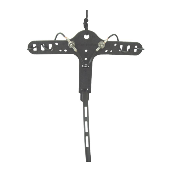
- Page 2 They feature an exclusive serpentine wire grip for insulated DX Engineering Antenna Wire and high strength, high power 300 Ω Ladder Line. The serpentine connection’s grip is strong enough to permanently support the antenna wires without the need for looping or wrapping the wire ends.
-
Page 3: Tools Required
You have purchased one of the following DX Engineering Universal Wire Antenna Kits: DXE-UWA-KIT: EZ-BUILD ® Center-T and End Insulators and hardware for wire and ladder line antennas or for feedpoint-mounted DX Engineering Baluns. Description Center-T End Insulator 10-24 x 3/4” Stainless Steel Carriage Bolt... -
Page 4: Basic Assembly
Note: JTL-12555 Jet-Lube SS-30 Anti-Seize is recommended to be used on all clamps, bolts and stainless steel threaded hardware to prevent galling and to ensure proper tightening. Basic Assembly Assembling the Center-T Support This initial assembly is common to all models. Holding the Center-T, insert a 3/4”... - Page 5 If you purchased the DXE-UWA-KIT and would like to add the coax strain relief, order DXE- CSR8X-1 for RG-8X, or DXE-CSR213-1 for RG-213 from DX Engineering. Coaxial Cable Strain Relief Bracket Assembly Both the DXE-UWA8X-KIT and DXE-UWA213-KIT contain the parts found in the DXE-UWA- KIT, (minus the #8 hardware) plus a cable/connector pigtail and cable strain relief.
- Page 6 Weatherproofing the Connectors Firmly attach your coaxial cable to the other end of the UHF Female to Female Adapter. If you choose to connect your cable after complete assembly, it will be more difficult to wrap the connectors. The PL-259s & UHF Female to Female Adapter should be weatherproofed using Temflex Rubber Splicing Tape which is a conformable self-fusing rubber electrical insulating tape.
- Page 7 Ensure the coaxial cable going through the P-clamps is properly aligned and has the coaxial cable loop as shown in Figure 8. Tighten all the parts holding the P-clamps and coaxial cable in place. Bottom View Top View Figure 8 – Center-T with Strain Relief Assembly& Coaxial Cable Attached Figure 9 –...
- Page 8 This center end of your dipole wire is then woven through the three slots on the Center-T. The three slots are designed to grip the DX Engineering DXE-ANTW antenna wire firmly when pulled tight. There is a small cupped out area in the first (outside) slot that allows a smooth transition for the wire as it enters the Center-T (Figure 13).
-
Page 9: Antenna Installation
Antenna Installation Safety Considerations WARNING! INSTALLATION OF ANY ANTENNA NEAR POWER LINES IS DANGEROUS Warning: Do not locate the antenna near overhead power lines or other electric light or power circuits, or where it can come into contact with such circuits. When installing the antenna, take extreme care not to come into contact with such circuits, because they may cause serious injury or death. -
Page 10: Support Line
For more hints, consult a reliable text such as the "ARRL Antenna Book" which is available from DX Engineering. Ideally, the messenger line should attach to the same structure used for the dipole, only above it, forming at least a 30 degree angle between the dipole and the messenger line to support the antenna. - Page 11 The top support hole may also be used for rope to install it as an inverted-V (Figure 16). Figure 16 – Inverted-V Dipole – Tower Side Arm Installation Tower side arm Universal Mounting Plates and Saddle Clamps are available from DX Engineering. Single Band Center Fed Half Wave Dipole When building a single band coaxial cable fed HF dipole antenna, you may easily use the formula L = 468/F to determine the overall length of the wire (L in feet, F in MHz).
- Page 12 The coax from a DX Engineering 1:1 Balun to the tuner should be kept short; typically 5 to 15 feet is best.
- Page 13 The 80 meter band starts at 3.5 MHz. Therefore, 123/3.5 = 35.1. DX Engineering feedline has a VF of 0.88, so 35.1 x 0.88 = 30.9 ft. per 1/8-wavelength. If 90 feet is required to get to your operating position, the nearest odd multiple 1/8 wavelength length is 92.7 feet (30.9 x 3).
- Page 14 Typical Dual Band Dipole using Ladder Line. Upper dipole leg wire is cut for lower frequency, lower dipole leg is cut wire for higher frequency (not to scale). Coaxial Feed DX Engineering UWA Kit with Strain Relief DX Engineering 300-ohm Transmitting Twinlead UV Resistant Support Rope...
- Page 15 Ladder Line Feed DX Engineering UWA Kit with DX Engineering 300-ohm Transmitting Twinlead UV Resistant Support Rope NOTES: - 15 -...
-
Page 16: Technical Support
All products manufactured by DX Engineering are warranted to be free from defects in material and workmanship for a period of one (1) year from date of shipment. DX Engineering’s sole obligation under these warranties shall be to issue credit, repair or replace any item or part thereof which is proved to be other than as warranted; no allowance shall be made for any labor charges of Buyer for replacement of parts, adjustment or repairs, or any other work, unless such charges are authorized in advance by DX Engineering.
Need help?
Do you have a question about the EZ-Build DXE-UWA-KIT and is the answer not in the manual?
Questions and answers