Advertisement
Quick Links
S
eries
How to Order
Clean series
10
21
Copper, fluorine and
silicon-free +
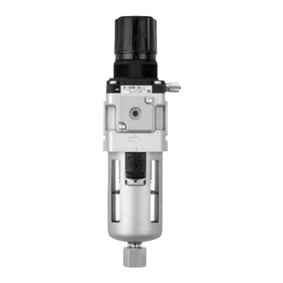
Filter regulator
Low particle generation
Thread type
Nil
Rc
Note 1)
N
NPT
Note 2)
F
G
Note 1) Drain guide is NPT 1/8 (applicable
to size 20), and NPT 1/4 (applicable
to size 30 and 40).
Note 2) Drain guide is G 1/8 (applicable to
size 20), and G 1/4 (applicable to
size 30 and 40).
When more than one specification is required, indicate in ascending alphanumeric order.
Note 5) The only difference from the standard specifications is the adjusting spring for the regulator. It does not restrict the setting of 0.2 MPa or more. Note 6) Without a valve function.
Note 7) For NPT thread type. This product is for overseas use only according to the new Measurement Law. (The SI unit type is provided for use in Japan.)
Accessory/Optional specifications
combinations
Accessory/Optional specifications
Standard specifications
Model
Port size
Fluid
Proof pressure
Maximum operating pressure
Set pressure range
Pressure gauge connection port size
Relief pressure
Ambient and fluid temperature
Nominal filtration rating
Drain capacity (cm
3
)
Drain guide port size
Construction
Grease
Particle generation grade
(Refer to front matter pages 13 to 22 for details.)
Accessory part no.
Applicable model
Accessory
Note 8)
Bracket assembly
1.0MPa
Note 9)
Pressure gauge
0.2MPa
Note 8) Assembly includes a bracket and set nuts. Note 9)
772
10-
AW
21-
AW
30
F
AW
30
F
Body size
20 30 40
Port size
Body size
Port
Symbol
size
20
30
01
1/8
—
02
1/4
03
3/8
—
—
04
1/2
—
—
—
06
3/4
Combination
With bracket
Round pressure gauge
With set nut
0.02 to 0.2 MPa setting
Metal bowl
Nylon bowl
Metal bowl with level gauge
With bowl guard
Drain guide
Non-relieving type
Flow direction: Right to left
Name plate, caution plate for bowl, and pressure gauge
in imperial units (PSI, °F)
10-/21-AW20
1/8, 1/4
1/8
Set pressure + 0.05 MPa (at relief flow rate of 0.1 l /min (ANR))
8
1/8
10-/21-AW20
AW20P-270AS
G49-10- 01
G49-2- 01
in part numbers for a pressure gauge indicates a type of connection thread. No indication is necessary for R; however, indicate N for NPT.
Filter regulator
03
BG
JN
03
BG
JN
Accessory
Note 3)
Applicable
Description
Symbol
model
—
Nil
—
20 to 40
B
With bracket
With round
pressure gauge
Note 4)
G
20 to 40
(Without limit
indicator)
With set nut
40
H
20 to 40
(For panel mount)
—
Note 3) Optional parts are not assembled and
are supplied loose at the time of
shipment.
Note 4) Pressure gauge mounting screw is 1/8
for size 20 and 30, and 1/4 for size
40. Pressure gauge is G49 type.
Combination available
Varies depending on the model
Accessory
Optional specifications
Symbol
B G H 1
2
6
B
G
H
–1
–2
–6
–8
–C
–J
–N
–R
–Z
10-/21-AW30
10-/21-AW40
1/4, 3/8
1/4, 3/8, 1/2
Air
1.5 MPa
1.0 MPa
0.05 to 0.85 MPa
1/8
–5 to 60°C (No freezing)
5 µm
25
1/4
Relieving type
10-: Fluorine grease
21-: Lithium soap based grease
10-: Grade 1
21-: Grade 1
10-/21-AW30
10-/21-AW40
AR30P-270AS
AR40P-270AS
G49-10- 01
G49-10- 02
G49-2- 01
G49-2- 02
∗ "J" must always be selected.
Option
Symbol
Description
Note 5)
1
0.02 to 0.2 MPa setting
2
Metal bowl
6
Nylon bowl
8
Metal bowl with level gauge
C
With bowl guard
Drain guide 1/8
Note 6)
J
Drain guide 1/4
N
Non-relieving
R
Flow direction: Right to left
Name plate, caution plate
Note 7)
for bowl, and pressure gauge
Z
in imperial units (PSI, °F)
Combination not available
Available only with NPT thread
Applicable filter regulator
8 C
J
N R
Z
10-/21-AW20
10-/21-AW40-06
3/4
1/4
1/4
45
45
1/4
1/4
10-/21-AW40-06
AR40P-270AS
G49-10- 02
G49-2- 02
Applicable
model
20 to 40
20 to 40
20 to 40
30, 40
20
20
30, 40
20 to 40
20 to 40
20 to 40
10-/21-AW30, 40
Advertisement

Subscribe to Our Youtube Channel
Related Manuals for SMC Networks 10-AW Series


Summary of Contents for SMC Networks 10-AW Series
- Page 1 eries Filter regulator How to Order Clean series ∗ "J" must always be selected. Option Copper, fluorine and Applicable Symbol Description Accessory Note 3) model silicon-free + Filter regulator Note 5) 0.02 to 0.2 MPa setting 20 to 40 Applicable Description Symbol Low particle generation...
- Page 2 Filter regulator Dimensions AW20 Panel fitting dimension Pressure gauge port size Bracket (Option) Applicable tubing ø6/4 Plate thickness 10-/21-AW20: Max. 3.5 Port size Pressure gauge (Option) Drain Hexagon width across flats 14 AW30 to 40-06 Panel fitting dimension Pressure gauge Bracket connection port size (Option)
-
Page 3: How To Order
AW K Series Filter regulator with back flow mechanism How to Order Clean series ∗ "J" must always be selected. Option Copper, fluorine and Note 3) Accessory Filter regulator silicon-free + Applicable Symbol Description model Low particle generation Applicable Symbol Description Body size model... - Page 4 AW K Filter regulator with back flow mechanism Dimensions AW20K Panel fitting dimension Pressure gauge port size Bracket (Option) Applicable tubing ø6/4 Plate thickness 10-/21-AW20K: Max. 3.5 Port size Pressure gauge (Option) Drain Hexagon width across flats 14 AW30K to 40K-06 Panel fitting dimension Pressure gauge port size Bracket...
- Page 5 F.R. Precautions 1 Be sure to read before handling. Design Selection Warning Warning 1. The standard bowl for the air filter and filter regulator are made of 1. The grease (10-: Fluorine, 21-: Mineral) used on internal sliding polycarbonate. Do not use in an environment where they are parts and seals may run down to outlet side components.
- Page 6 F.R. Precautions 2 Be sure to read before handling. Mounting Adjustment Caution Warning 1. To avoid reversed connections of the air inlet/outlet, make 1. Regulator and filter regulator connections after confirming the "IN/OUT" mark or arrows that 1) Set the regulator while verifying the displayed values of the indicate the direction of air flow.
-
Page 7: Maintenance
F.R. Precautions 3 Be sure to read before handling. Maintenance Warning 1. When disassembly or installation is required during the maintenance, repair, or replacement of a device, be sure to follow the instructions provided in the instruction manual or safety instructions in this catalog.
Need help?
Do you have a question about the 10-AW Series and is the answer not in the manual?
Questions and answers