
Subscribe to Our Youtube Channel
Related Manuals for Charder MS4900


Summary of Contents for Charder MS4900
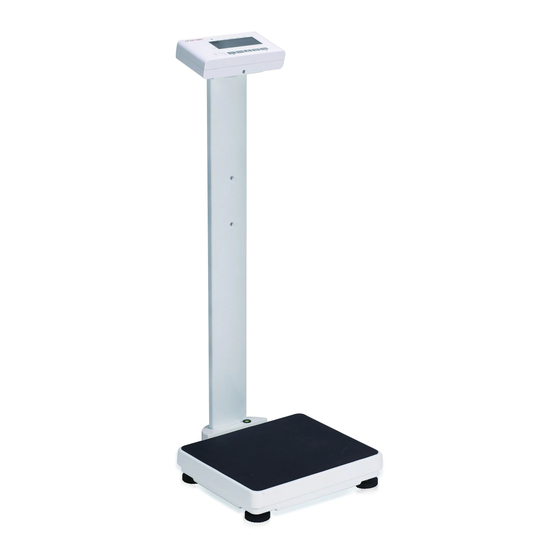
- Page 1 USER MANUAL MS4900 Stand-on Floor Scale Please keep the instruction manual at hand all the time for future reference.
- Page 2 Explanation of Graphic Symbols on Label/Packaging Caution, consult Authorized accompanying documents representative in the before use European Community Manufacturer of medical Indicates that device device conforms to International Organization of Legal Metrology (Class III) requirements Manufacturing year of Indicates that device medical device conforms to 2014/31/EU Non...
- Page 3 This user manual is protected by international copyright law. All content is licensed, and usage is subject to written authorization from Charder Electronic Co., Ltd. (hereinafter Charder) Charder is not liable for any damage caused by a failure to adhere to requirements stated in this manual.
-
Page 4: Table Of Contents
CONTENTS I. Safety Notes ................5 A. General Information ............. 5 B. EMC Guidance and Manufacturer's Declaration ......8 II. Installation ................13 A. Assembly ................13 B. Inserting Batteries ............. 16 C. Using Adapter ..............17 D. Attaching Height Rod to Column .......... 18 E. -
Page 5: Safety Notes
I. Safety Notes A. General Information Thank you for choosing this Charder Medical device. It is designed to be easy and straightforward to operate, but if you encounter any problems not addressed in this manual, please contact your local Charder service partner. - Page 6 If results are inaccurate, please contact local distributor. Warranty/Liability If Charder is responsible for a fault or defect present upon receipt of the unit, Charder shall either repair the fault, or supply a replacement unit.
- Page 7 Charder service partner, using original Charder accessories and spare parts. Charder is not liable for any damages arising from improper maintenance or usage. Dismantlement of the device will void the warranty.
-
Page 8: Emc Guidance And Manufacturer's Declaration
B. EMC Guidance and Manufacturer's Declaration Guidance and manufacturer’s declaration-electromagnetic emissions The MS4900 Stand-on Floor Scale is intended for use in the electromagnetic environment specified below. The customer or the user of the device should assure that it is used in such an environment. - Page 9 Guidance and manufacturer’s declaration-electromagnetic immunity The MS4900 Stand-on Floor Scale is intended for use in the electromagnetic environment specified below. The customer or the user of the device should assure that it is used in such an environment. IEC 60601...
- Page 10 Guidance and manufacturer’s declaration-electromagnetic immunity The MS4900 Stand-on Floor Scale is intended for use in the electromagnetic environment specified below. The customer or the user of the device should assure that is used in such an environment. IEC 60601 test...
- Page 11 Over the frequency range 150 kHz to 80 MHz, field strengths should be less than 3 V/m. Recommended separation distance between portable and mobile RF communications equipment and the MS4900 Stand-on Floor Scale The device is intended for use in an electromagnetic environment in which radiated RF disturbances are controlled.
- Page 12 transmitter in watts (W) according to the transmitter manufacturer. NOTE1 At 80 MHz and 800 MHz, the separation distance for the higher frequency range applies. NOTE2 These guidelines may not apply in all situations. Electromagnetic propagation is affected by absorption and reflection from structures, objects and people.
-
Page 13: Installation
II. Installation A. Assembly Standard Column 1. Fasten and tighten four screws at the bottom of the base. Ensure four adjustable feet and stability foot are at same level before using device. Four screws Castor wheel column 1. Fasten and tighten four screws at the bottom of the base... - Page 14 2. Ensure four adjustable feet and stability foot are at the same level before using the device. Rotate counter-clockwise to extend, clockwise to retract Adjustable feet Stability foot...
- Page 15 3. Retract stability foot before moving device using castor wheels Note: rotate counter-clockwise to extend, clockwise to retract Ensure stability foot is retracted before using castor wheels...
-
Page 16: Inserting Batteries
B. Inserting Batteries 1. Open battery housing cover 2. Remove battery housing 3. Insert batteries 4. When inserting battery housing, ensure contact with housing pins is correct. 5. Re-insert battery housing. 6. Close battery housing cover. -
Page 17: Using Adapter
C. Using Adapter 1. Connect adapter to indicator before connecting to mains power supply 2. Disconnect adapter from mains power supply before unplugging adapter pin from indicator. -
Page 18: Attaching Height Rod To Column
D. Attaching Height Rod to Column Standard (Narrow) Column Step 1. Attach two fixing blocks to Step 2. Attach height rod to blocks column using four flat-head using two flat-head screws screws Item Name Quantity Fixing block screws Fixing blocks Height Rod to fixing block screws * Photo of display for reference only. - Page 19 Castor Wheel Column 1. Assemble two brackets on the column Item Name Quantity M5x0.8x11 round head screw Relief Bushing Bracket for HM200D/HM201D/HM201M * Photo of display for reference only. Please refer to the actual product.
- Page 20 2. Attach Height Rod to bracket and tighten screws. Item Name Quantity Height Rod (Compatible with: HM200D/HM201D/HM201M) M5x10L flat head screw Fixing block M5x0.8x11 * Photo of display for reference only. Please refer to the actual product.
-
Page 21: Attaching Thermal Printer
E. Attaching Thermal Printer Standard (Narrow) Column Washer head screw M5*0.8*15mm Cross head screw M4*0.7*6mm... - Page 22 Castor Wheel Column Item Parts M5*15L head screw Screws for printer bracket Printer bracket...
- Page 23 1. Install the side bracket 2. Install the thermal printer on the bracket...
-
Page 24: Indicator
III. Indicator A. Indicator and Key Functions Height (lb not available on OIML-approved model) Key Function (UNIT): Switch between units. For OIML-approved version, only kg is activated. (PRINT): When printer or PC is connected to the scale, press this key to print results. (ON/OFF/ZERO): Turn device on and off. -
Page 25: Display Layout
B. Display layout Stable Hold Negative Zero Gross Battery level Hold: Hold function is activated BMI: BMI function is activated kg: Current unit is kg Stable: Weight is stable. Net: Current result is net weight Negative: Weight is under zero Zero: Weight is at zero Gross: Current result is gross weight. -
Page 26: Using Device
IV. Using Device A. Basic Operation Switch on the device using key. The device will automatically perform self-calibration, displaying software version. Once "0.00 kg" appears on indicator, device is ready for measurement. Note: If "0.00 kg" does not display on indicator, press key to zero the device. -
Page 27: Bmi
C. BMI 1. Weigh subject normally. After "stable" symbol appears on indicator, press the key to enter BMI mode. 2. Display will show last recorded height. Left-most digit will flash. 3. Enter height using numeral keys (ex: 170 cm). Input will automatically move to next digit. -
Page 28: Device Setup
V. Device Setup When the device is switched on, press and hold the key for about 3 seconds, until the display shows the "SEt”, followed by "A.OFF” (first option in setting menu). In device setup menu: to toggle menu option to confirm selection / enter submenu Auto Power-Off: Instruct device to shut off automatically after a certain period of time. - Page 29 selection. Bluetooth (optional): If device has Bluetooth module installed, Bluetooth function can be turned on or off. Press [HOLD] to toggle between on/off, and [TARE] to confirm selection. Wi-Fi (optional): If device has Wi-Fi module installed, Wi-Fi function can be turned on or off. Press [HOLD] to toggle between on/off, and [TARE] to confirm selection.
-
Page 30: Setup Usb Connection To Pc
USB 2.0 or above. Operators should select a USB cable length that is most suitable to the operating environment. 1. Charder Smart Data Manager can be used to connect the device to a PC. The software program can be downloaded from the Charder website: [LINK URL] https://www.chardermedical.com/download.htm... - Page 31 Conducting Measurement 1. Input subject's first name, last name, patient ID, date of birth (DD/MM/YYYY), gender, and height (for BMI calculation) into software if needed. Press [Clear] to clear all input. NOTE: information can also be input after weight measurement. 2.
- Page 32 Saving & Printing Results 1. Press [Save as] to save measurement results as .csv file on PC. Default file name is same as user ID. (ex: 20190201.csv) To track changes and multiple measurements for the same subject, we recommend not changing the default file name. 2.
-
Page 33: Wireless Connection
3. Press the printer icon to print out result using a printer connected to the PC. VII. Wireless Connection If the device has the wireless or bluetooth module installed, the indicator can transmit measurement results wirelessly. Please see Charder wireless or bluetooth software instructions for details. -
Page 34: Troubleshooting
Warranty Program & Return Policy. 1. If Charder is responsible for a fault or defect present upon receipt of the unit, Charder shall either repair the fault, or supply a replacement unit. - Page 35 Ensure printer is supplied with power. Ensure PC software is set up properly as indicated in this manual Distributor support required If the following errors occur, we recommend contacting your local Charder distributor for repair or replacement services: 1. Device will not power on Faulty on/off key ...
- Page 36 Error Messages Error Message Reason Action Low battery warning Replace batteries, or Voltage of battery is too plug in adapter low to operate device Overload Reduce weight on Total load exceeds measurement device's maximum platform and try again capacity Counting Error (too Error normally caused high) by faulty loadcell or...
-
Page 37: Product Specifications
IX. Product Specifications A. Device Information Model MS4900 Display DP3400 Weight Capacity 0-200 kg x 0.2 kg Measurement 200-300 kg x 0.5 kg Accuracy 0-200 kg ± 0.3 kg 200-300 kg ± 0.75 kg OIML Class III LCD Screen 1.2-inch LCD screen (5 1/2 digits) -
Page 38: Standard Accessories
B. Standard Accessories Accessories Item Spec. Qty. Standard column: M6 x 20 flat head screw Castor wheel column: M4 x 20 round head screw 12V adapter DC adapter RS232 cable WR-8159 User manual CD-IN-1089... -
Page 39: Power Adapter Standards
C. Power Adapter Standards Warning The device is only compatible with the power adapters specified in the dashed block below. -
Page 40: Declaration Of Conformity
Non-automatic Weighing Instruments Directive Please see separate document showing on sticker of device for above CE marking. Authorized EU Representative: Manufactured by: Charder Electronic Co., Ltd. No.103, Guozhong Rd., Dali Dist., Taichung City, 412 Taiwan (R.O.C.) CD-IN-1089 REV XXX 09/2020...
Need help?
Do you have a question about the MS4900 and is the answer not in the manual?
Questions and answers