
Related Manuals for Charder MS4910


Summary of Contents for Charder MS4910
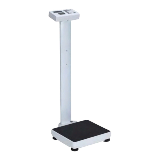
- Page 1 USER MANUAL MS4910 (DP3710) Medical Scale Please keep the instruction manual at hand all the time for future reference.
- Page 2 Carefully read this operation manual before setup commissioning, even if you are already familiar with Charder scales. Manufacturing date Lot number or batch number Charder Electronic Co., Ltd. No. 103, Guozhong Rd., Dali Dist., Taichung City, 412 Taiwan...
- Page 3 This user manual is protected by international copyright law. All content is licensed, and usage is subject to written authorization from Charder Electronic Co., Ltd. (hereinafter Charder) Charder is not liable for any damage caused by a failure to adhere to requirements stated in this manual.
-
Page 4: Table Of Contents
CONTENTS I. Safety Notes ................5 A. Precaution Symbols .............. 5 B. General Information ............. 5 C. EMC Guidance and Manufacturer's Declaration ......9 II. Installation ................13 A. Assembly ................13 B. Inserting Batteries ............. 16 C. Using Adaptor ..............19 D. -
Page 5: Safety Notes
Hazard icon warning against possible electric shock. B. General Information Thank you for choosing this Charder Medical device. It is designed to be easy and straightforward to operate, but if you encounter any problems not addressed in this manual, please contact your local Charder service partner. - Page 6 Charder service partner, using original Charder accessories and spare parts. Charder is not liable for any damages arising from improper maintenance or usage. Dismantlement of the device will void the warranty.
- Page 7 Warranty/Liability If Charder is responsible for a fault or defect present upon receipt of the unit, Charder shall either repair the fault, or supply a replacement unit.
- Page 8 Do not remove the plug by yanking on the cable. Use only a correctly wired (100-240VAC) outlet, and do not use a multiple outlet extension cable. Do not under any circumstances dismantle or alter the device, as this could result in electric shock or injury as well as adversely affect the precision of measurements.
-
Page 9: Emc Guidance And Manufacturer's Declaration
C. EMC Guidance and Manufacturer's Declaration Guidance and manufacturer’s declaration-electromagnetic emissions The MS4910 is intended for use in the electromagnetic environment specified below. The customer or the user of the MS4910 should assure that it is used in such an environment. Electromagnetic Emission test... - Page 10 Guidance and manufacturer’s declaration-electromagnetic immunity The MS4910 is intended for use in the electromagnetic environment specified below. The customer or the user of the MS4910 should assure that it is used in such an environment. Immunity IEC 60601 Compliance Electromagnetic...
- Page 11 Guidance and manufacturer’s declaration-electromagnetic immunity The MS4910 is intended for use in the electromagnetic environment specified below. The customer or the user of the MS4910 should assure that is used in such and environment. IEC 60601 test Compliance Electromagnetic Immunity test...
- Page 12 RF communications equipment and the MS4910 The MS4910 is intended for use in an electromagnetic environment in which radiated RF disturbances are controlled. The customer or the user of the MS4910 can help prevent electromagnetic interference by maintaining a minimum distance between...
-
Page 13: Installation
II. Installation A. Assembly Standard Column 1. Fasten and tighten four screws at the bottom of the base. Ensure four adjustable feet and stability foot are at same level before using device. Four screws Castor wheel column 1. Fasten and tighten four screws at the bottom of the base... - Page 14 2. Ensure four adjustable feet and stability foot are at the same level before using the device. Rotate counter-clockwise to extend, clockwise to retract Adjustable feet Stability foot...
- Page 15 3. Retract stability foot before moving device using castor wheels Note: rotate counter-clockwise to extend, clockwise to retract Ensure stability foot is retracted before using castor wheels...
-
Page 16: Inserting Batteries
B. Inserting Batteries Fig. 1 - Open the battery housing cover Take out the battery housing Fig. 2 - Accessing batteries Fig. 3 - Use either rechargeable battery pack, or AA-size batteries... - Page 17 Rechargeable Battery Housing AA-size Battery Housing Fig. 4 -Ensure batteries are installed into the housing correctly Fig. 5 - Install the battery housing into the compartment, and make sure the right side of housing pin is facing towards inside of the connecting position...
- Page 18 Fig. 6 - Slide back the cover to close the battery housing compartment. Turn on power to confirm that battery is correctly installed. Regarding Rechargeable Battery (optional) The rechargeable battery should be recharged at least once every 3 months, regardless of if the device has been used. Battery can be charged by plugging the device's exclusive adaptor into AC Connector Port.
-
Page 19: Using Adaptor
C. Using Adaptor 1. Connect AC adaptor to indicator before connecting to mains power supply 2. Disconnect AC adaptor from mains power supply before unplugging AC adaptor pin from indicator. AC Connector Port... -
Page 20: Attaching Height Rod To Column
D. Attaching Height Rod to Column Standard (Narrow) Column Step 1. Attach two fixing blocks to Step 2. Attach height rod to blocks column using four flat-head using two flat-head screws screws Item Name Quantity Fixing block screws Fixing blocks Height Rod to fixing block screws * Photo of display for reference only. - Page 21 Castor Wheel Column 1. Assemble two brackets on the column Item Name Quantity M5x0.8x11 round head screw Relief Bushing Bracket for HM200D/HM201D/HM201M * Photo of display for reference only. Please refer to the actual product.
- Page 22 2. Attach Height Rod to bracket and tighten screws. Item Name Quantity Height Rod (Compatible with: HM200D/HM201D/HM201M) M5x10L flat head screw Fixing block M5x0.8x11 * Photo of display for reference only. Please refer to the actual product.
- Page 23 Connecting height rod to indicator (HM200D/HM201D) Digital height rod data transmission port on indicator...
-
Page 24: Attaching Thermal Printer
E. Attaching Thermal Printer Standard (Narrow) Column Washer head screw M5*0.8*15mm Cross head screw M4*0.7*6mm... - Page 25 Castor Wheel Column Item Parts M5*15L head screw Screws for printer bracket Printer bracket...
- Page 26 1. Install the side bracket 2. Install the thermal printer on the bracket...
-
Page 27: Indicator
III. Indicator A. Indicator and Key Functions (Wireless functionality optional) Key Function 1. ON/OFF: Power on or power off. 2. ZERO: Reset display to 0.0 kg display (can be used if within ±2% of full capacity). Press and hold for 3 seconds to enter device settings. 3. -
Page 28: Display Layout
B. Display layout Definitions Stable symbol: Indicate that weight is stable. Zero symbol: Weight is at zero Minor weight: Weight under zero. Low battery: Battery needs to be charged or replaced. -
Page 29: Getting Started
IV. Getting Started A. Power and connections 1. Install batteries into battery compartment of indicator, or plug in 12V AC Adaptor to Connector Port. AC Connector Port USB Connector 2. If thermal printer is used: Plug USB data transmission cable into device's USB Connector port. Plug other end of cable into printer. -
Page 30: Setting Time & Date
B. Setting Time & Date Press and hold [HOLD] key for 3 seconds to enter Time Setting mode. Example: Inputting 2008, Dec 25, 8:00am Year Setting Enter year using numeral keys 0-9. Press [HOLD] key once completed to proceed to month & date setting. Month &... -
Page 31: Device Setup
C. Device Setup When the device is switched on, press and hold the [ZERO] key for about 3 seconds, until the display shows the "SETUP”, followed by "A.OFF” (first option in setting menu). In device setup: [TARE] key to scroll down ↓ [ZERO] key to scroll up ↑... - Page 32 Wi-Fi Version After selecting menu option: [HOLD] key to toggle between options [TARE] key to confirm selection...
- Page 33 Auto-Off Instruct device to shut off automatically after a certain period of time. Auto off options: 120 sec / 180 sec / 240 sec / 300 sec / off Press [HOLD] to toggle, and[TARE] key to confirm selection. Ex: To select "240 seconds" as the auto-off time, press the [HOLD] key until 240 S is displayed on the screen.
- Page 34 Hold Stop On/Off When Hold Stop is "on", Hold will deactivate after subject leaves measurement platform Press [HOLD] to toggle, and[TARE] key to confirm selection. Wi-Fi transfer setting If "Auto" is selected, weight measurement will be automatically sent to connected printer or device. If "PKEY" is selected, transfer will occur manually after [PRINT] key is pressed.
-
Page 35: Using Device
V. Using Device A. Basic Operation Switch on the device using [ON/OFF] key. The device will automatically perform self-calibration, displaying software version. Once "0.00 kg" appears on indicator, device is ready for measurement. Note: If "0.00 kg" does not display on indicator, press [ZERO] key to zero the device. -
Page 36: Bmi (W/Hm200D Or Hm201D)
4. After inputting height, press [ZERO] to confirm. 5. Proceed to weigh subject as usual. Indicator will display weight, height, and BMI. NOTE: Hold function can be used at this time if weight is unstable 6. Press [BMI] key to return to normal mode. D. -
Page 37: Pre-Tare
F. Pre-Tare The Pre-Tare function is used to subtract the known weight of a substance prior to weighing. The MS4910 can store 5 sets of pre-tare values. Pre-tare values can be stored using two different methods: "Load Weight", or "Input Manually". - Page 38 B. Input Manually DESCRIPTION EXAMPLE Press [PRE-TARE] key. Left-most digit will begin blinking. If no further action is taken within 6 seconds, indicator will return to normal mode While digit is blinking: Enter pre-tare weight using 0~9 keys. Ex: to pre-tare 5.0 kg of weight, press 0-0-5-0.
- Page 39 Press numeral key 1 ~ 5 to assign this number with the current pre-tare weight. Press [ENTER] key to store pre-tare weight; the indicator will make a beep sound. C. Recall Pre-Tare Weight DESCRIPTION EXAMPLE Press and hold [PRE-TARE] key for 3 seconds.
-
Page 40: Print
Press [CLEAR] key to return to Normal Mode NOTE: Pre-tare weight must be under max capacity, otherwise screen will show 0.00 after [ENTER] key is pressed, and the operator will have to re-input pre-tare settings. G. Print If thermal printer is connected to indicator, results can be printed by pressing [PRINT] key. -
Page 41: Setup Usb Connection To Pc
1. Connect USB cable to device indicator and PC. For first-time use, PC will automatically download drivers. 2. Charder Smart Data Manager can be used to connect the device to a PC. The software program can be downloaded from the Charder website: [LINK URL] https://www.chardermedical.com/download.htm... - Page 42 Conducting Measurement 1. Input subject's first name, last name, patient ID, date of birth (DD/MM/YYYY), gender, and height (for BMI calculation) into software if needed. Press [Clear] to clear all input. NOTE: information can also be input after weight measurement. 2.
- Page 43 Saving & Printing Results 1. Press [Save as] to save measurement results as .csv file on PC. Default file name is same as user ID. (ex: 20190201.csv) To track changes and multiple measurements for the same subject, we recommend not changing the default file name. 2.
-
Page 44: Wireless Connection
3. Press the printer icon to print out result using a printer connected to the PC. VII. Wireless Connection If the device has the wireless or bluetooth module installed, the indicator can transmit measurement results wirelessly. Please see Charder wireless or bluetooth software instructions for details. -
Page 45: Troubleshooting
Warranty Program & Return Policy. 1. If Charder is responsible for a fault or defect present upon receipt of the unit, Charder shall either repair the fault, or supply a replacement unit. - Page 46 Ensure printer is supplied with power. Ensure PC software is set up properly as indicated in this manual Distributor support required If the following errors occur, we recommend contacting your local Charder distributor for repair or replacement services: 1. Device will not power on Faulty on/off key ...
- Page 47 Error Messages Error Message Reason Action Low battery warning Replace batteries, or Voltage of battery is too plug in AC adaptor low to operate device Overload Reduce weight on Total load exceeds measurement device's maximum platform and try again capacity Counting Error (too Error normally caused high)
-
Page 48: Product Specifications
IX. Product Specifications A. Device Information Model MS4910 Display DP3710 Weight Capacity 300kg x 0.1kg Measurement Accuracy ±0.15kg OIML Class III LCD Screen 1.0-inch LCD screen (5 1/2 digits) Dimensions Overall 360(W) x 480(D) x 1100(H) mm (Standard) Platform 360(W) x 310(D) x 70(H) mm... -
Page 49: Power Adapter Standards
B. Power Adapter Standards Warning The device is only compatible with the power adaptors specified in the dashed block below. -
Page 50: Declaration Of Conformity
X. Declaration of Conformity A. EU Declaration of Conformity... -
Page 51: Federal Communications Commission (Fcc) Statement
B. Federal Communications Commission (FCC) Statement This device complies with Part 15 of the FCC Rules. Operation is subject to the following two conditions: 1) This device may not cause harmful interference, and 2) This device must accept any interference received, including interference that may cause undesired operation of the device. -
Page 52: Manufacturer's Declaration Of Conformity
Non-automatic Weighing Instruments Directive Please see separate document showing on sticker of device for above CE marking. Authorized EU Representative: Manufactured by: Charder Electronic Co., Ltd. No.103, Guozhong Rd., Dali Dist., Taichung City, 412 Taiwan (R.O.C.) CD-IN-1269 REV 001 03/2020...
Need help?
Do you have a question about the MS4910 and is the answer not in the manual?
Questions and answers